Copyright © 2013 IJECCE, All right reserved 966
International Journal of Electronics Communication and Computer Engineering Volume 4, Issue 3, ISSN (Online): 2249–071X, ISSN (Print): 2278–4209
An Improved Interpolative Vector Quantization Scheme
for Image Compression
Ms. Darshana Chaware, Ms. Tarannum Pathan
Abstract—The aim of this paper is to develop a new image compression scheme by introducing visual patterns to interpolative vector quantization (IVQ). In this scheme first input images are down-sampled by ideal filter. Then, the down sampled images are compressed lossly by JPEG and transmitted to the decoder. In the decoder side, the decoded images are first up-sampled to the original resolution. The codebook is designed using LBG algorithm. We introduce visual patterns on designing the codebook. Experiment results shows that our scheme achieves much better performance over JPEG in terms of visual quality and PSNR.
Keywords – Image Compression, JPEG, Vector Quantization, Visual Pattern.
I. I
NTRODUCTIONImage compression is an important aspect of multimedia data transmission, especially through band limited, time-varying channels. Compression can be classified into lossless or lossy, depending on whether all the information is retained or some of it is discarded during compression process [1]. There are two kinds of quantization: scalar quantization (SQ) and vector quantization (VQ). SQ involves processing the input samples individually whereas VQ involves processing the input samples in groups. SQ involves mapping of each individual input to an output using some distortion measure. VQ involves mapping a group of inputs into a set of well defined vectors using some distortion measure. According to Shannon’s Rate Distortion Theory, it has been proved that better results would be obtained by processing a block of data as vectors instead of processing the data individually as scalars because vectors makes good use of the statistics of the signal. Vector quantization achieves more compression than scalar quantization [2]. The quality of the reconstruction depends on the rate allocation among the different sub bands and also the code vector dimension [3]. Linda, Buzo and Gray (LBG) first proposed an iterative vector quantizer design algorithm by using clustering approach [4].
In order to achieve low bit rate, many VQ schemes, such as side-match VQ (SMVQ), classified SMVQ (CSMVQ), Gradient based SMVQ (GSMVQ), Jigsaw-puzzle vector quantization (JPVQ) [5]-[8], have been proposed. However, the low bit rate schemes, SMVQ, CSMVQ, GSMVQ and JSPVQ require high encoding time than that of VQ method. The modified vector quantization scheme gives better PSNR values and low bit rate than GSMVQ and JPVQ [9].
Interpolative vector quantization, first proposed explicitly by Gersho [10], introduces dimension reduction to traditional VQ. The codebook in the encoder is learned on down sampled vectors and the codebook in the decoder
on high-dimension vectors. VQ encoder maps down-sampled inputs to a set of scalar indices and VQ decoder reproduces high-dimension inputs by received indices. The important parameter that indicates the quality of the reconstruction is peak to peak signal-to-noise ratio (PSNR). This paper proposes a new image compression scheme by introducing visual patterns into IVQ. The proposed VQ is designed to reproduce the information of visual patterns removed by down sampling.
II. P
ROPOSEDC
OMPRESSIONS
CHEMEOur image compression scheme consists of VQ encoder and VQ decoder. In the encoder side, input image is first down-sampled by an ideal filter. Ideal filter is used for down sampling and up sampling. This scheme does not need a codebook in the encoder side either. But the encoder has to know which kind of down sampling is used and what the parameters are in the training process to generate codebook. The down-sampled image is compressed lossly by JPEG. JPEG encoder gives the compressed image which is then transmitted to the decoder.
Now the key problem is to reproduce the details removed by down sampling. In the decoder side, the decoded image is first up-sampled by the ideal filter to the original resolution. The clustering method used is LBG [11]. Finally, the decoded image and visual patterns are blended together to reproduce input image.
Fig.1. a) VQ encoder
Copyright © 2013 IJECCE, All right reserved 967
International Journal of Electronics Communication and Computer Engineering Volume 4, Issue 3, ISSN (Online): 2249–071X, ISSN (Print): 2278–4209
A. Image Down sampling and Up sampling
Down sampling and up sampling are two fundamental and widely used image operations, with applications in image display, compression, and progressive transmission. Down sampling is the reduction in spatial resolution while keeping the same two-dimensional (2D) representation. It is typically used to reduce the storage and/or a transmission requirement of images. Up sampling is the increasing of the spatial resolution while keeping the 2D representation of an image. It is typically used for zooming in on a small region of an image, and for eliminating the pixilation effect that arises when a low-resolution image is displayed on a relatively large frame. More recently, down sampling and up sampling have been used in combination in lossy compression multi resolution lossless compression and progressive transmission. The standard methods for down/up sampling are decimation/duplication and bilinear interpolation, which yield low visual performance. Ideal filter is used for down sampling and up sampling. The ideal down/up sampling scheme is one where both filters g and p are low pass filters with pass-band equal to [0 π/2]. In this scheme, the aliasing distortion is zero, and the reconstructed signal preserves the largest possible range of low frequencies. The down sampling/up sampling scheme is shown in fig. 2 and the result after downsampling is shown in fig. 3(b)
Fig.2. Down sampling / up sampling scheme
Fig.3. a) Input image Fig.3. b) downsampled image
B. JPEG (Joint Photographic Experts Group)
This standard is used for compressing continuous tone still pictures, full color or grayscale images of scenes by exploiting redundancies. This algorithm performs in following steps:
1. Input image of some standard size is fed to the encoder in the form of image say 8×8.
2. JPEG algorithm applies a discrete cosine transformation to each block to size 8×8 separately. The output of each DCT is an 8×8 matrix of DCT coefficients.
3. After DCT, JPEG performs quantization in which less important DCT coefficients are wiped out. This transformation is done by dividing each of the coefficients in 8×8 DCT matrix by quantization table element.
4. The DC components are reduced that in the matrix, (0, 0) value of each block.
5. It linearizes the 64 elements and applies run length encoding to the list zig-zag scanning pattern is used. 6. Huffman encoding encodes the numbers for storage or
transmission.
The JPEG encoder is shown in fig. 4 and results after JPEG encoding and up sampling are shown in fig.5 (a) and (b)
Fig.4. JPEG Encoder
For decoding a JPEG images we require to run the algorithm backward.
Fig.5. a) JPEG image Fig.5. b)Upsampled image
C. Visual Pattern
Visual patterns, a concept first introduced by Chen and Bovik, are image blocks representing visually meaningful information. In order to achieve reasonable compression ratios, the psycho visual redundancies which exist in natural images have to be exploited, i.e. visually meaningful information is preserved while visually insignificant data is discarded. Chen and Bovik introduced a compression technique for grayscale images called visual pattern image coding which based on the way the human visual system responds to different image features [12].
It is the description of intensity variations in images and their local geometries in the Marr’s vision theory. It not only contains intensity variations but also implicates geometric edge information. Using primal sketch priors can significantly improve the visual quality of image hallucination. The visual pattern is the feature which mainly characterizes the variation in primal patches without taking the magnitude of intensity into account.
D. LBG Algorithm
Clustering is an important instrument in engineering and other scientific disciplines. Its applications cover several fields such as audio and video, data compression, pattern recognition, and medical image recognition and so on. In 1980 Linde, Buzo and Gray (Linde et al., 1980) proposed an improvement of the Lloyd’s technique (Lloyd, 1957).
Copyright © 2013 IJECCE, All right reserved 967
International Journal of Electronics Communication and Computer Engineering Volume 4, Issue 3, ISSN (Online): 2249–071X, ISSN (Print): 2278–4209
A. Image Down sampling and Up sampling
Down sampling and up sampling are two fundamental and widely used image operations, with applications in image display, compression, and progressive transmission. Down sampling is the reduction in spatial resolution while keeping the same two-dimensional (2D) representation. It is typically used to reduce the storage and/or a transmission requirement of images. Up sampling is the increasing of the spatial resolution while keeping the 2D representation of an image. It is typically used for zooming in on a small region of an image, and for eliminating the pixilation effect that arises when a low-resolution image is displayed on a relatively large frame. More recently, down sampling and up sampling have been used in combination in lossy compression multi resolution lossless compression and progressive transmission. The standard methods for down/up sampling are decimation/duplication and bilinear interpolation, which yield low visual performance. Ideal filter is used for down sampling and up sampling. The ideal down/up sampling scheme is one where both filters g and p are low pass filters with pass-band equal to [0 π/2]. In this scheme, the aliasing distortion is zero, and the reconstructed signal preserves the largest possible range of low frequencies. The down sampling/up sampling scheme is shown in fig. 2 and the result after downsampling is shown in fig. 3(b)
Fig.2. Down sampling / up sampling scheme
Fig.3. a) Input image Fig.3. b) downsampled image
B. JPEG (Joint Photographic Experts Group)
This standard is used for compressing continuous tone still pictures, full color or grayscale images of scenes by exploiting redundancies. This algorithm performs in following steps:
1. Input image of some standard size is fed to the encoder in the form of image say 8×8.
2. JPEG algorithm applies a discrete cosine transformation to each block to size 8×8 separately. The output of each DCT is an 8×8 matrix of DCT coefficients.
3. After DCT, JPEG performs quantization in which less important DCT coefficients are wiped out. This transformation is done by dividing each of the coefficients in 8×8 DCT matrix by quantization table element.
4. The DC components are reduced that in the matrix, (0, 0) value of each block.
5. It linearizes the 64 elements and applies run length encoding to the list zig-zag scanning pattern is used. 6. Huffman encoding encodes the numbers for storage or
transmission.
The JPEG encoder is shown in fig. 4 and results after JPEG encoding and up sampling are shown in fig.5 (a) and (b)
Fig.4. JPEG Encoder
For decoding a JPEG images we require to run the algorithm backward.
Fig.5. a) JPEG image Fig.5. b)Upsampled image
C. Visual Pattern
Visual patterns, a concept first introduced by Chen and Bovik, are image blocks representing visually meaningful information. In order to achieve reasonable compression ratios, the psycho visual redundancies which exist in natural images have to be exploited, i.e. visually meaningful information is preserved while visually insignificant data is discarded. Chen and Bovik introduced a compression technique for grayscale images called visual pattern image coding which based on the way the human visual system responds to different image features [12].
It is the description of intensity variations in images and their local geometries in the Marr’s vision theory. It not only contains intensity variations but also implicates geometric edge information. Using primal sketch priors can significantly improve the visual quality of image hallucination. The visual pattern is the feature which mainly characterizes the variation in primal patches without taking the magnitude of intensity into account.
D. LBG Algorithm
Copyright © 2013 IJECCE, All right reserved 968
International Journal of Electronics Communication and Computer Engineering Volume 4, Issue 3, ISSN (Online): 2249–071X, ISSN (Print): 2278–4209
They extended Lloyd’s results from mono- to k-dimensional cases. For this reason their algorithm is known as the Generalized Lloyd Algorithm (GLA) or LBG from the initials of its authors.
The LBG algorithm is a finite sequence of steps in which, at every step, a new quantizer, with a total distortion less or equal to the previous one, is produced. We can distinguish two phases as shown in figure 6. The initialization of the codebook and its optimization. The LBG algorithm is of iterative type and in each iteration a large set of vectors, generally referred to as training set, and is needed to be processed. The flowchart for the codebook optimization is shown in fig. 5.
Fig.6. LBG procedure
Initialization of the Codebook
The codebook initialization is a very important task. In the initialization phase two methods are mainly used: random and by splitting.
Fig.7. LBG codebook optimization
Codebook Optimization
The codebook starts from an initial codebook and after some iterations, generates a final codebook with a distortion corresponding to a local minimum.
The steps used for LBG algorithm are
1) Determine the number of code words or the size of the codebook.
2) Select N codeword at random, and let that be the initial codebook. The initial code word can be randomly chosen from the set of input vectors.
3) Using the Euclidean distance measure, clusterize the vectors around each codeword.
4) Compute the new set of codewords.
5) Repeat steps 3 and 4 until the either the codewords don't change or the change in the codewords is small. The flowchart of LBG codebook optimization is shown in fig. 7 and result are shown in fig. 8(a) and (b).
Fig.8. a) Codebook image Fig.8. b) Restored image
III. V
ECTORQ
UANTIZATIONThere are two different kinds of quantization for data compression: scalar quantization and vector quantization. The lossy compression scheme can be analyzed using Rate distortion theory. In this scheme the decompressed data will not be a replica of the original data. VQ is a very powerful method for lossy compression of data such as images and speech. A vector quantizer can be considered as a generalization of a scalar quantizer. In the case of VQ a set of symbols is combined to represent the input. A vector can describe almost any type of signal such as speech or image. VQ can be considered as a pattern recognizer where an input pattern is approximated by a predetermined set of standard patterns. VQ produces superior performance over SQ even when the components of the input vectors are statistically independent. VQ exploits the linear and nonlinear dependence among vectors. It also provides flexibility in choosing multi dimensional quantizer cell. The fractional value of resolution that is achievable. This is very important for low bit rate applications where low resolution is sufficient. Typically, a Vector Quantizer comprises of two blocks namely, the encoder and decoder.
IV. E
XPERIMENTALR
ESULTSTo evaluate IIVQ scheme we carried out experiment on standard gray scale images. The size of image taken is 256×256. The input image is first down-sampled 1/5th of size in each dimension and is compressed by JPEG. The Copyright © 2013 IJECCE, All right reserved
968
International Journal of Electronics Communication and Computer Engineering Volume 4, Issue 3, ISSN (Online): 2249–071X, ISSN (Print): 2278–4209
They extended Lloyd’s results from mono- to k-dimensional cases. For this reason their algorithm is known as the Generalized Lloyd Algorithm (GLA) or LBG from the initials of its authors.
The LBG algorithm is a finite sequence of steps in which, at every step, a new quantizer, with a total distortion less or equal to the previous one, is produced. We can distinguish two phases as shown in figure 6. The initialization of the codebook and its optimization. The LBG algorithm is of iterative type and in each iteration a large set of vectors, generally referred to as training set, and is needed to be processed. The flowchart for the codebook optimization is shown in fig. 5.
Fig.6. LBG procedure
Initialization of the Codebook
The codebook initialization is a very important task. In the initialization phase two methods are mainly used: random and by splitting.
Fig.7. LBG codebook optimization
Codebook Optimization
The codebook starts from an initial codebook and after some iterations, generates a final codebook with a distortion corresponding to a local minimum.
The steps used for LBG algorithm are
1) Determine the number of code words or the size of the codebook.
2) Select N codeword at random, and let that be the initial codebook. The initial code word can be randomly chosen from the set of input vectors.
3) Using the Euclidean distance measure, clusterize the vectors around each codeword.
4) Compute the new set of codewords.
5) Repeat steps 3 and 4 until the either the codewords don't change or the change in the codewords is small. The flowchart of LBG codebook optimization is shown in fig. 7 and result are shown in fig. 8(a) and (b).
Fig.8. a) Codebook image Fig.8. b) Restored image
III. V
ECTORQ
UANTIZATIONThere are two different kinds of quantization for data compression: scalar quantization and vector quantization. The lossy compression scheme can be analyzed using Rate distortion theory. In this scheme the decompressed data will not be a replica of the original data. VQ is a very powerful method for lossy compression of data such as images and speech. A vector quantizer can be considered as a generalization of a scalar quantizer. In the case of VQ a set of symbols is combined to represent the input. A vector can describe almost any type of signal such as speech or image. VQ can be considered as a pattern recognizer where an input pattern is approximated by a predetermined set of standard patterns. VQ produces superior performance over SQ even when the components of the input vectors are statistically independent. VQ exploits the linear and nonlinear dependence among vectors. It also provides flexibility in choosing multi dimensional quantizer cell. The fractional value of resolution that is achievable. This is very important for low bit rate applications where low resolution is sufficient. Typically, a Vector Quantizer comprises of two blocks namely, the encoder and decoder.
IV. E
XPERIMENTALR
ESULTSTo evaluate IIVQ scheme we carried out experiment on standard gray scale images. The size of image taken is 256×256. The input image is first down-sampled 1/5thof size in each dimension and is compressed by JPEG. The Copyright © 2013 IJECCE, All right reserved
968
International Journal of Electronics Communication and Computer Engineering Volume 4, Issue 3, ISSN (Online): 2249–071X, ISSN (Print): 2278–4209
They extended Lloyd’s results from mono- to k-dimensional cases. For this reason their algorithm is known as the Generalized Lloyd Algorithm (GLA) or LBG from the initials of its authors.
The LBG algorithm is a finite sequence of steps in which, at every step, a new quantizer, with a total distortion less or equal to the previous one, is produced. We can distinguish two phases as shown in figure 6. The initialization of the codebook and its optimization. The LBG algorithm is of iterative type and in each iteration a large set of vectors, generally referred to as training set, and is needed to be processed. The flowchart for the codebook optimization is shown in fig. 5.
Fig.6. LBG procedure
Initialization of the Codebook
The codebook initialization is a very important task. In the initialization phase two methods are mainly used: random and by splitting.
Fig.7. LBG codebook optimization
Codebook Optimization
The codebook starts from an initial codebook and after some iterations, generates a final codebook with a distortion corresponding to a local minimum.
The steps used for LBG algorithm are
1) Determine the number of code words or the size of the codebook.
2) Select N codeword at random, and let that be the initial codebook. The initial code word can be randomly chosen from the set of input vectors.
3) Using the Euclidean distance measure, clusterize the vectors around each codeword.
4) Compute the new set of codewords.
5) Repeat steps 3 and 4 until the either the codewords don't change or the change in the codewords is small. The flowchart of LBG codebook optimization is shown in fig. 7 and result are shown in fig. 8(a) and (b).
Fig.8. a) Codebook image Fig.8. b) Restored image
III. V
ECTORQ
UANTIZATIONThere are two different kinds of quantization for data compression: scalar quantization and vector quantization. The lossy compression scheme can be analyzed using Rate distortion theory. In this scheme the decompressed data will not be a replica of the original data. VQ is a very powerful method for lossy compression of data such as images and speech. A vector quantizer can be considered as a generalization of a scalar quantizer. In the case of VQ a set of symbols is combined to represent the input. A vector can describe almost any type of signal such as speech or image. VQ can be considered as a pattern recognizer where an input pattern is approximated by a predetermined set of standard patterns. VQ produces superior performance over SQ even when the components of the input vectors are statistically independent. VQ exploits the linear and nonlinear dependence among vectors. It also provides flexibility in choosing multi dimensional quantizer cell. The fractional value of resolution that is achievable. This is very important for low bit rate applications where low resolution is sufficient. Typically, a Vector Quantizer comprises of two blocks namely, the encoder and decoder.
IV. E
XPERIMENTALR
ESULTSCopyright © 2013 IJECCE, All right reserved 969
International Journal of Electronics Communication and Computer Engineering Volume 4, Issue 3, ISSN (Online): 2249–071X, ISSN (Print): 2278–4209
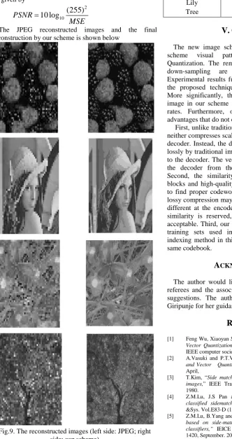
decoded image is first up-sampled and finally the decoded image and visual pattern are blended together to reproduce input image. The PSNR (db) of JPEG and our method is shown in TABLE I. The performances are evaluated in terms of bit rate and peak signal-to-noise ratio (PSNR) in db given by
2
10
(255)
10 log
PSNR
MSE
The JPEG reconstructed images and the final reconstruction by our scheme is shown below
Fig.9. The reconstructed images (left side: JPEG; right side: our scheme)
Table I: PSNR for JPEG and our Method
Images JPEG Method
PSNR (db)
Our Method PSNR (db) Berries
Lena Lily Tree
29.77 26.87 27.22 28.35
29.87 26.90 27.25 28.43
V. C
ONCLUSIONThe new image scheme is developed by introducing scheme visual pattern into interpolative vector Quantization. The removed details in silent regions by down-sampling are reproduced by our method. Experimental results fully demonstrate the advantages of the proposed techniques and the overall performance. More significantly, the visual quality of reconstructed image in our scheme is very good even at very low bit rates. Furthermore, our scheme also presents some advantages that do not exist in other VQ schemes.
First, unlike traditional vector quantization, our scheme neither compresses scalar indices nor transmits them to the decoder. Instead, the down-sampled image is compressed lossly by traditional image coding scheme and transmitted to the decoder. The vector indices are finally extracted in the decoder from the decoded down-sampled image. Second, the similarity between blurred visual pattern blocks and high-quality visual pattern blocks are utilized to find proper codewords in the codebook. Although the lossy compression may make blurred visual pattern blocks different at the encoder and the decoder, as long as the similarity is reserved, the reconstructed quality is still acceptable. Third, our scheme potentially allows different training sets used in different decoders because the indexing method in this paper does not request the exact same codebook.
A
CKNOWLEDGMENTThe author would like to express his gratitude to the referees and the associate editor for their comments and suggestions. The author would like to thank Mrs. S. Giripunje for her guidance and technical suggestions.
R
EFERENCES[1] Feng Wu, Xiaoyan Sun, “Image Compression by Visual Pattern Vector Quantization (VPVQ)”, DataCompression Conference, IEEE computer society, 2008.
[2] A.Vasuki and P.T.Vanathi,“Image Compression using Lifting and Vector Quantization”, GVIP Journal, Volume 7, Issue 1, April,
[3] T.Kim, “Side match and overlap match vector quantizers for images,” IEEE Trans. Image. Process. vol.28 (1), pp.84-95, 1980.
[4] Z.M.Lu, J.S Pan and S.H Sun, “Image Coding Based on classified sidematch vector quantization,” IEICE Trans. Inf.
&Sys. Vol.E83-D (12), pp.2189-2192, Dec. 2000.
Copyright © 2013 IJECCE, All right reserved 970
International Journal of Electronics Communication and Computer Engineering Volume 4, Issue 3, ISSN (Online): 2249–071X, ISSN (Print): 2278–4209
[6] Chia-Hung Yeh, “Jigsaw-puzzle vector quantization for image compression”, Opt.Eng Vol.43, No.2, pp. 363-370, Feb-2004. [7] K. Somasundaram and S. Domnic, “Modified Vector
Quantization Method for Image Compression”, PSASET volume
13 MAY 2006
[8] Gersho, “Optimal nonlinear interpolative vector quantization”,
IEEE trans. on communication, vol. 38, pp 1285-1287, 1990. [9] G. Patane, M. Russo, “The enhanced LBG algorithm,” Neural
Networks, vol. 14, pp 1219-1237, 2001.
[10] Chen, D. Bovik, A.(1990) “Visual pattern image coding”,IEEE Transactions On Communication, Vol. 38, pp. 2137-2146. [11] J. Sun, N. N. Zheng, H. Tao, H. Y. Shum, “Image hallucination
with primal sketch priors,” International Conference on
Computer Vision and Pattern Recognition, vol. 2, pp. 729-736, 2003.
[12] Khalid Sayood, Introduction to Data Compression, Harcourt India Private Limited, New Delhi, 2nd edition, 2000.
A
UTHOR’SP
ROFILED. Chaware
D.O.B. 02/07/1983
She obtained her B.E degree in Electronics and Tele Communication Engineering from G.H. Raisoni College of Engineering, Nagpur in the year 2005.
She obtained her Master’s degree in Electronics Engineering from G.H. Raisoni college of Engineering, Nagpur. Her area of interest is image processing.
She has 4 years of Teaching Experience. She is currently working as a lecturer in the department of Electronics Engineering, Rajiv Gandhi College of Engineering and Research, Nagpur. India.
Ms. Chaware is a lifetime member of ISTE.
Tarannum Pathan
D.O.B 24/09/1986
She is pursuing her M.tech (4th SEM) in Electronics Engineering from Yeshwantrao Chavan college of Engineering, Nagpur. She completed her B.E in Electronics Engineering from Rajiv Gandhi College of Engineering, Research & Technology, and Chandrapur in the year 2008. Her area of interest is Digital Image Processing and VLSI.