http: // www.ijrtsm.com© International Journal of Recent Technology Science & Management 18
IJRTSM
INTERNATIONAL JOURNAL OF RECENT TECHNOLOGY SCIENCE & MANAGEMENT
“
DESIGN, ANALYSIS & FABRICATION OF HYDRAULIC RAM PUMP FOR REMOTE AREAS
”
Sagar Manghani
1, Prof. MD Irshad
21,2 Acropolis Technical Campus, Indore (M.P.)
ABSTRACT
Electric pumps are a requirement in almost every location on the planet as water is to be pumped to higher locations for its use in various activities. In places where there is no electricity, generators are installed to power the pumps. There is a continuous consumption of costly energy in such a practice.
The aim of the project is to construct and design a pump that has practically no running cost and needs minimum maintenance, simple in construction and fulfilled the required specifications. This was to provide isolated villages with water and as a replacement to generator driven pumps that are used by farmers to water their lands.
To achieve this goal, various alternative pump designs were studied keeping in view the good and bad in each design. In the end a selection was made on the basis of figure of merits of each pump design.
KEYWORDS: Assembly line balancing, methods, Ranked Positional Weight Method, Plant simulation software.
I.
I
NTRODUCTIONA hydraulic ram pump (also called hydram) is a pump that uses energy from a Falling quantity of water to pump some of it to an elevation much higher than the original level at the source. The basic idea behind a ram pump is simple. The pump uses the momentum of relatively large amount of moving water to pump a relatively small amount of water uphill. No other energy is required and as long as there is a continuous flow of falling water, the pump will work continuously and automatically. The hydraulic ram pump (hydram) is an alternative pumping device that is relatively simple technology that uses renewable energy, and is durable. The hydram has only two moving parts: these are impulse valve and delivery valve which can be easily maintained. Ram pumps have been around for many decades and are popular for two main reasons:
They need no external source of power - the force of moving water gives them the power they need.
They are extremely simple, with just two moving parts.II.
DESIGN
PROCEDURE
• Before a ram can be selected, several design factors must be known.
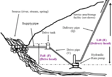
• The difference in height between the water source and the pump site (called vertical fall). • The difference in height between the pump site and the point of storage or use (lift). • The quantity (Q) of flow available from the source.
• The quantity of water required.
http: // www.ijrtsm.com© International Journal of Recent Technology Science & Management 19
• The length of pipe from the pump to the storage site (called the delivery pipe).
• Once this information has been obtained, a calculation can be made to see if the amount of water needed can be supplied by a ram.
III.
DESIGN
PARAMETERS
The detailed mechanics of hydraulic ram operation are not well understood. Several parameters relating to the operation of the hydraulic ram are:
• Drive pipe length (L)
• Cross-sectional area of the drive pipe (A) • Drive pipe diameter (D)
• Supply head (F) • Delivery head (E)
• Available flow through drive pipe (V) • Pumping flow rate (Q)
• Friction head loss in the drive pipe • Friction head loss at the delivery valve. The formula is: Q = (V x F x 0.60)/ E Where: Q = Pumping flow rate. V = Available flow through drive pipe.
F = Supply head or Vertical distance between pump and source available. E = Vertical distance between pump and storage tank
http: // www.ijrtsm.com© International Journal of Recent Technology Science & Management 20
IV.
B
ILLO
FM
ATERIALFOR
¾
THINCH
RAM
PUMP
V.
CALCULATION
S.NO PART NAME QUANTITY
1 Valve ¾’’ 1
2 Tee ¾’ 1
3 Union ¾’’ 1
4 Swing Check Valve ¾’’ 1
5 Spring Check Valve ¾’’ 1
6 Tee ½ 1
7 Valve ½’’ 1
8 Union ½’ 1
9 Bushing ¾’’x ½’ 1
10 2’’ end cap 1
11 2’’ x 28’’ pipe 1
12 Drive pipe 3/4” x 10 1
13 Delivery pipe ½’’ x 15’ 1
14 Delivery pipe ½’’ x 15’ 1
http: // www.ijrtsm.com© International Journal of Recent Technology Science & Management 21
Inlet pipe diameter = 0.75 inch = 0.019m
Outlet pipe diameter = 0.5inch = 0.012m
Length of drive pipe (150 ≤ L/D ≤1000) L = D*150 =(0.75*150)/12
= 9.37
≈10ft ( = 3.04m)
Height of fall, F = 5ft = 1.52m
Height of elevation, E = 15 ft = 4.5m
Length of delivery pipe = Sinθ = P/H Taking θ = 60
Sin60 = 15/H H =17.3ft (= 5.2m)
Available flow, V = 7 l/min
Volumetric flow rate through delivery pipe, Q = 1.5 l/min
Efficiency, η = Q*E/V*F = (1.5*15)/(7*5) = 0.642
η = 64.2%
Velocity of fluid flow, Vd = Q/Ad
= Q/(π/4d2) Vd = 2.44 m/s
Reynolds number,
Re = Vd / ν ( ν = kinematic viscosity at temperature 20 C is 1.004*10-6 m2/s.) Re = 2.44*106/1.004
= 2.43*106
Frictional factor,
http: // www.ijrtsm.com© International Journal of Recent Technology Science & Management 22
= 7.99*10-3
Head loss = (fL/D)*(Vd2/2)
= ((7.99*10-3*10*12*2.54/0.75*2.54))*(2.442/2) = 3.80cm
= 0.038m
V
I.
CAD
MODEL
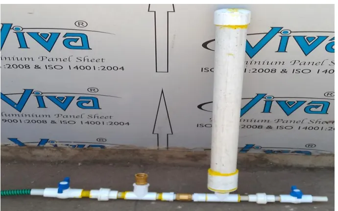
Fig 2. CAD Model
http: // www.ijrtsm.com© International Journal of Recent Technology Science & Management 23
VII.
RESULTS
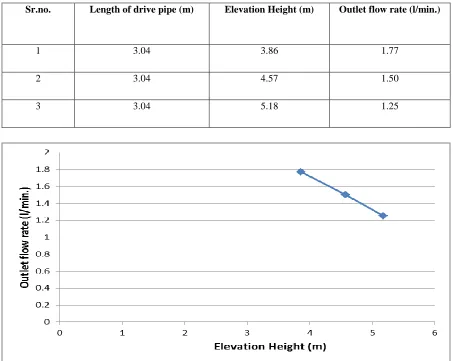
7.1 Observation Table
Table No.1 Result from given data
Sr.no. Length of drive pipe (m) Elevation Height (m) Outlet flow rate (l/min.)
1 3.04 3.86 1.77
2 3.04 4.57 1.50
3 3.04 5.18 1.25
Fig. 4 Graph between Variation of Rate of Outlet Water Flow with the Change in Elevation Height
VIII.
CONCLUSION
http: // www.ijrtsm.com© International Journal of Recent Technology Science & Management 24
discharge at various points in the set up doesn't remain constant. Variation in the diameter of the air chamber will change the outlet pressure and the discharge. Therefore an optimum dimension could be determined by experimentation. By providing water recirculation system maximum wastage of water is prevented which is vital in rural areas.
REFERENCES
Fluid mechanics and hydraulic machines by R.K.Bansal, laxmi publication pvt ltd.
C. A. Nwosu and T. C. Madueme, “Recycled micro hydropower generation using hydraulic ram pump (hydram)”, International Journal of Research in Engineering & Technology, vol. 1, no. 3, (2013), pp. 110.
F. Zoller, J. Woudstra and M. van der Wiel, “Hydraulic ram pumping in rural community development”, (2004).
IJIRST –International Journal for Innovative Research in Science & Technology| Volume 2 | Issue 10 | March 2016
S. Sheikh, C. C. Handa and A. P. Ninawe, “Design methodology for hydraulic ram pump (hydram)”, International journal of mechanical engineering and robotic research, vol. 2, no. 4, (2013), pp. 170-175.
Hydraulic machines by R.K.Rajput.