Volume 17, Number 3, pp. 251–270. http://www.scpe.org
ISSN 1895-1767 c
⃝2016 SCPE
COMMUNICATION-AWARE APPROACHES
FOR TRANSPARENT CHECKPOINTING IN CLOUD COMPUTING
SAMY SADI∗AND BELABBAS YAGOUBI
Abstract. Checkpoint/Restart or checkpointing is a fault tolerance technique which consists on taking frequent snapshots of an application, so that, in the event of a failure, the application’s state can be restored and the application’s execution continued without necessarily restarting it. The advent of Cloud Computing brought new challenges with regard to this technique as Fault Tolerance needs to be supplied transparently in environments running highly heterogeneous applications. In this context, we propose two new fully transparent checkpointing approaches. Both approaches use communication-induced checkpointing and guarantee a consistent view of the applications with regard to the outside world process. The first approach is uncoordinated and creates checkpoints for applications independently. The second approach is coordinated, and applications are first grouped into clusters before the checkpointing process is started. We have compared the proposed approaches with state of the art approaches. The results show that our approaches perform better when considering the communication latencies, and the overhead on the execution of the Virtual Machines.
Key words: Cloud Computing, Fault Tolerance, Uncoordinated Checkpointing, Coordinated Checkpointing, Dynamic Clus-tering, Performance Evaluation, Simulation
AMS subject classifications. 68M14, 68M15, 68M20, 68U20
1. Introduction. Over the past few years, Cloud Computing [2, 17] has been adopted increasingly as the key solution to satisfy the ever-growing need for computing, storage and networking resources. Among its different strengths and promises, Cloud Computing allows users to easily deploy their applications and control running costs while delegating the hassle of infrastructure management and quality of service enforcement to the provider. This one should, for its part, use different techniques to guarantee resources availability and to offer a secure and fault tolerant environment for users.
With regard to fault tolerance, the Cloud provider’s task is to ensure that, in the event of a failure, there is no data loss and deployed applications can continue to run flawlessly. This property is very important as failures are not uncommon in the Cloud. In fact, failures are rather a rule than an exception due to the high number of machines and the frequent use of commodity hardware [24]. To illustrate this point, a previous study characterising failures in the Cloud estimated that a proportion of 8% of the machines can expect to see at least one failure each year [24].
In this context, many research efforts have been devoted to address the issue of failures and to make Clouds more reliable. These efforts found strong existing foundations as fault tolerance has already been addressed for decades in computer systems, especially in High Performance Computing (HPC) systems where the average job length is high and job resubmissions costly. Therefore, research on fault tolerance in Cloud Computing mainly focused on adapting and extending existing techniques, while taking into account Cloud specificities. For instance, much effort has been put forth to design transparent and application agnostic fault tolerance techniques that could be leveraged directly by the provider [6, 15, 20].
Among these, checkpointing [8], sometimes referred to as checkpoint/restart, enables applications to con-tinue running even after the occurrence of a failure. This is achieved by taking frequent snapshots (or check-points) of the running application’s state, which are saved on secondary hardware. Thus, if the primary machine where the application is running fails, the application’s state is not lost and a secondary machine can be used to restore the application and continue its execution.
Despite the apparent simplicity of this process, two main issues remain. The first issue arises when con-sidering the efficiency of the checkpointing process, as it should induce a low overhead on the application’s execution and on the application’s communications. The second issue arises when considering the behaviour of the checkpointed application, as it should not display any inconsistencies to other applications due to the checkpointing process.
∗University of Oran1 Ahmed Ben Bella, Department of Computer Science, Oran, Algeria, ([email protected]) University of Oran1 Ahmed Ben Bella, Department of Computer Science, Oran, Algeria, ([email protected])
In this paper, we address both of these issues by proposing two fully transparent checkpointing approaches for Cloud Computing environments. Both of the approaches are communication-aware as they guarantee a consistent view of the checkpointed applications and they induce a minimal overhead on the communications.
The first proposed approach is uncoordinated. It takes checkpoints for each application separately. The second approach is coordinated. It orchestrates the checkpoint creation among multiple applications after automatically grouping them into clusters.
We have simulated the proposed approaches, and compared them with three other state of the art ap-proaches. The results show that our approaches are better when taking into account both the overhead on the communications and on the execution of the checkpointed applications.
The organisation of the paper is as follows. In the next section, we review existing research on checkpoint-ing. Next, we present our uncoordinated and coordinated checkpointing approaches in Sect. 3 and in Sect. 4 respectively. After that, in Sect. 5, we describe the evaluation of the two proposed approaches and their com-parison with three other state of the art approaches. Finally, we conclude and give a preview of our future work in Sect. 6.
2. Related Work. Checkpointing has been extensively addressed in the literature, and much work has been done to improve existing checkpointing approaches and to reduce the checkpointing overhead while guar-anteeing an acceptable level of fault tolerance.
A part of these works have undertaken to determine the optimum checkpointing frequency [26, 23]. They have established that a random selection of the checkpointing frequency leads to poor performances, as high values generate high overhead on the application’s execution and low values induce poor fault tolerance.
Another part of the literature focused on reducing checkpoints’ size by using several means. One of them is data compression [11], which comes with an added overhead during the creation of the checkpoint. An-other is incremental checkpointing [1, 9], which relies on identifying and saving the changed state between two consecutive checkpoints instead of saving the whole application’s state.
From the implementation perspective of the checkpointing process, three main categories of approaches are described in the literature: application level, user level and system level [7]. The two first categories regroup approaches that need access to the application’s code or to the system’s libraries. The latter category regroups approaches that are fully transparent. These are preferred in Cloud Computing environments since the control of the providers over the applications is limited.
The literature abounds with examples of system level checkpointing approaches. Most of them rely on the virtualisation layer to easily create checkpoints for whole operating systems [4, 6, 20, 25]. Each operating system being confined in a Virtual Machine (VM), the content of the checkpoints can easily be determined by monitoring memory changes, disk operations and network operations. The checkpoints can then be saved in a secondary machine [6], in memory [25] or in a dedicated checkpoint repository [20].
Our first contribution in this paper consists on extending and improving the existing system level check-pointing system Remus [6]. The choice of Remus has been motivated by two main points. Firstly, Remus offers notable performances as it enables high-frequency checkpointing and can generate checkpoints as often as every 25ms [6]. Secondly, Remus is one of the few checkpointing systems that ensure the consistency of input/output (I/O) communications by using an output commit mechanism (also used in [19]), which is all the more impor-tant to ensure a correct execution of the applications. Further description of Remus and of our contribution are given in Sect. 3.
Our second and main contribution in this paper is given in Sect. 4. As many other existing works in the literature, we have addressed the checkpointing coordination issue. However, unlike the majority of the existing contributions which propose application and user level approaches [8], we propose a system level approach. This ties in with many similar efforts including: VCCP [21], VNSnap [13] and ATCCp [18].
VCCP [21] is a virtual cluster checkpointing system that enables checkpointing coordination among multiple VMs. It uses a blocking algorithm to orchestrate the checkpointing process and the recovery process in a virtual cluster. Both of these processes are initiated by the head node of the virtual cluster and require a reliable FIFO data transmission channel.
Creation Transmission
Ack + Buffer release Initiate
1 2 3
Delay
Fig. 3.1.Checkpointing process of Remus
authors adapted an existing and non-blocking global snapshot algorithm [16] and showed its applicability. On a different note, ATCCp, an intra-server coordinated checkpointing approach, has been proposed in [18]. Checkpointing coordination is achieved by taking checkpoints at the same moment based on the VMs’ clocks. The main issue raised by the authors is related to the fact that clocks can deviate and thus are not reliable enough. They propose to overcome the issue by using message logging and by piggybacking extra information in the VMs’ communications.
There are many differences between our approach and the previously described approaches. The main difference is that previous approaches assume that VMs are grouped in predefined and static virtual clusters, whereas our approach dynamically groups VMs into different clusters. Considering the highly heterogeneous nature of the applications deployed in the Cloud, this improves the transparency of our approach and enhances its performances. Furthermore, while other approaches in the literature only take into account communications of the VMs inside the same virtual cluster, our approach also considers the communications with other systems, whether it is a VM in another cluster or a system outside the Cloud. Such communications are referred in the following as communications to the outside world process (OWP).
3. Improving Remus Using Communication-Induced Checkpointing. Remus [6] is a prominent system level checkpointing approach which enables high-frequency checkpointing while guaranteeing a moderate overhead on the running applications. It is one of the few system level approaches in the literature that keep consistent communications in a faulty environment. However, the output commit mechanism employed to this extent causes an additional delay for communications which is directly dependent on the checkpointing frequency. In fact, to keep reasonable communication latencies, the checkpointing frequency should be high enough which in turn may degrade applications’ performances.
In this section, we address this particular issue by using communication-induced checkpointing where we define two types of checkpoints: regular periodic checkpoints, and forced communication-induced checkpoints.
We start by giving an overview of Remus. Then we present current issues with Remus and we bring into view the relationship between the communication latencies and the checkpointing frequency. Finally, we present our contribution.
3.1. Overview of Remus. Remus [6] is a system level checkpointing approach that offers a high degree of fault tolerance. It associates for each VM on a primary machine, a backup VM on a secondary machine which is frequently updated to be near to identical to the primary VM. When the primary VM fails, the secondary VM is started and becomes the new primary VM. The recovery process is totally transparent to the user, as even network addresses of the failed VM are reassigned to the newly started VM.
The checkpointing process defined by Remus is illustrated in Fig. 3.1. It consists of multiple sequences of three stages. During the first stage, the VM is paused and a checkpoint file is created by including the execution state of the VM and all modified memory pages since the last checkpoint. Next, in the second stage, the VM is running speculatively and all network output is buffered. During this stage, the checkpoint file is transmitted to the secondary machine. Once the checkpoint is fully transmitted and acknowledged, all network output that has been buffered before the first stage is released and sent asynchronously to the outside world process (OWP). Finally, during the third stage, the VM continues to run speculatively for a given delay depending on the checkpointing frequency.
Buffer
VM execution
OWP
IN
1
O
U
T
1
O
U
T
2
O
U
T
3
O
U
T
1
IN
2
O
U
T
2
O
U
T
4
Checkpoint Created
Checkpoint ACK
Fig. 3.2.Time diagram displaying the output commit mechanism used by Remus [6]
output is first buffered and is released only once a corresponding checkpoint has been acknowledged. Particularly, the output data which is generated after the checkpoint creation (OUT3 and OUT4) is not released immediately, but is released only after another checkpoint is created and acknowledged. This ensures that, when recovering from a failure, the secondary VM will not re-generate the same output.
With regard to disk operations, these are immediately and asynchronously sent to the secondary machine where they are buffered and applied once a checkpoint has been acknowledged. If the primary VM fails before the checkpoint is fully transmitted then the buffered disk operations are discarded.
3.2. Issues with Remus. The main issues with Remus come from the output commit mechanism which is necessary to keep a consistent execution of the VM, but induces an extra-latency on the communications and potentially a notable packet loss.
The extra-latency is due to communications’ buffering, which retains the VM’s output until a committed (i.e. acknowledged) checkpoint is produced. This aspect incites to use higher checkpointing frequencies to reduce the retention delay and attenuate the latency. However, this also comes at the expense of a higher overhead on the VM’s execution.
The other issue concerns the loss of network packets which can affect both the incoming and the outgoing communications, and can happen both during the normal execution of the VM or after a failure.
Loss of input packets during the execution of the VM can happen because of the previously described extra-latency. When the VM takes too long to answer a request, the OWP may assume that the request (i.e. input) is lost and that it has not reached the VM.
Additionally, after a failure, any input that has been sent since last committed checkpoint is lost. Indeed, at the moment of the failure, the secondary VM’s state is identical to the primary VM’s state when the last committed checkpoint has been created. Thus, it does not reflect the alterations brought by new input.
Likewise, failures can also cause output packet loss. This happens when a failure occurs after the second stage of the checkpointing process when buffered output is being released. The failure will interrupt the output release process and will prevent some packets to be sent. Moreover, when recovering, Remus will not try to resend those packets because last acknowledged checkpoint assumes that they are already transmitted.
A potential solution to the previous issues, when caused by failures, can be envisioned by using packets duplication and logging mechanisms on the secondary machine. However, this will induce a higher overhead on the VM’s execution during the checkpointing process. Moreover, since failures are uncommon, and since network communications are usually considered unreliable, Remus can rely on application level protocols (e.g. TCP) to handle packet loss when necessary. Thus, and in light of these elements, addressing failure-induced communication issues is usually worthless. However, communication issues introduced by the checkpointing process during the failure-free execution of the VM should be addressed. These have more frequent consequences and can highly deteriorate the quality of service perceived from the OWP.
3.3. Contribution. In our contribution, we focus on reducing the network communication latencies which are introduced by the checkpointing process during the failure-free execution of the VM. In particular, we enable to reduce the checkpointing frequency, and thus the checkpointing overhead on the VM’s execution, with a moderate effect on the communication latencies.
initiated as soon as possible when there is pending buffered output. This new checkpoint addresses the previous issues regarding communication latencies, and packet loss due to communication latencies.
Because taking forced checkpoints immediately after output is available may overburden the VM’s execution, we set a small delayαbefore taking a forced checkpoint. Moreover, before taking a forced checkpoint, we ensure that we do not interfere with another checkpoint which is being created or transmitted. Finally, before initiating the forced checkpoint, we ensure that there is still buffered output waiting to be released. In fact, it is possible that another checkpoint has released the buffered output while waiting for theαdelay.
In sum, we define the following steps for taking a forced checkpoint: 1. Wait for buffered output;
2. Wait for a specific time (a delay, denoted by α);
3. If in stage 1 (i.e. checkpoint creation) or in stage 2 (checkpoint transmission) of the checkpointing process (cf. Fig. 3.1) then wait for stage 3;
4. Make sure that there is still buffered output waiting to be released, otherwise go back to the first step; 5. Stop current checkpointing (i.e. stage 3), and immediately initiate a new checkpoint starting from
stage 1 (cf. Fig. 3.1); 6. Go back to the first step.
The selection of theαparameter should be done by taking into account two factors. First, it should be big enough to not interfere with the VM execution. Secondly, it should be short enough to minimise communication latencies. In particular with regard to this last point, theαparameter should be set so that the VM response time is short enough to avoid packet loss. If we assume that the OWP will wait for the delayθbefore considering that a packet is lost, then the VM response time should be smaller thanθ.
On another note, the VM response time after buffering output depends on theαparameter, the checkpoint creation delayδand the delay for transferring the checkpoint to the secondary machine. This last delay can be computed knowing the checkpoint file sizeS and the available bandwidthB when transferring the checkpoint from the primary to the secondary machine.
We obtain the following inequation when bounding the response time with theθparameter:
ResponseTime =δ+ S
B +α6θ (3.1)
Thus, we obtain the following upper bound for theαparameter to avoid packet loss:
αmax=θ−δ−
S
B (3.2)
We define no lower bound for α. Clearly, lower values will give smaller communication latencies but they will also generate higher overhead on the VM’s execution. Similarly, higher values will generate lower overheads but higher latencies. A compromise would be to set:
α=1
2 ·αmax (3.3)
4. System Level Coordinated Checkpointing Approach. In this section, we present our approach for system level checkpointing coordination. We extend our approach described in Sect. 3 by using a dynamic clustering approach and by coordinating the checkpoint creation at each cluster level.
This approach eliminates the latencies introduced by the checkpointing process for intra-cluster communi-cations. Moreover, when compared with other approaches in the literature, our approach brings two novelties. First, our dynamic clustering approach enables to define optimum cluster sizes which will reduce the periodic checkpointing overhead while keeping a moderate effect on communication latencies to the OWP. Secondly, we do not only focus on keeping a consistent execution state inside the same cluster. We also strive to keep a global consistent state with regard to the OWP.
Hardware Hypervisor
VM1
...
VMmHost 1
Hardware Hypervisor
B.VM1
...
B.VMmBackup Host 1
Host 2 Backup
Host 2
...
Host n Backup
Host n Coordinator
(Replica)
Coordinator
Daemon Daemon
Fig. 4.1.System Design used in the proposed approach
4.1. Overview of the proposed approach. Guaranteeing a consistent global state for applications during the checkpointing process and after recovery in the event of a failure is an important property. The un-coordinated checkpointing approach presented in Sect. 3 provides this property by using a buffering mechanism which ensures that no state of the VM is made externally visible until a checkpoint is created. This is a viable solution, but has many drawbacks on the communications. In particular, using the proposed communication-induced checkpoints can indeed potentially reduce communication latencies but it will also cause important overheads for communication-intensive VMs.
To address these issues, we propose to improve the previous approach by using two techniques: clustering and checkpointing/recovery coordination. In the first technique, we propose to identify highly-coupled VMs and to group them into the same cluster. In the second technique, we propose to coordinate the checkpointing process and the recovery process among all VMs belonging to the same cluster. In particular, creating a checkpoint for a VM in a given cluster will imply creating a checkpoint for all VMs in that cluster. Similarly, if a VM in a given cluster fails, then all VMs in that cluster are rolled back accordingly to the previous checkpoint.
As a result, communications inside each cluster can be immediately delivered without introducing incon-sistencies or extra-latencies. However, VMs’ communications to the OWP (i.e. VMs in other clusters) still have to be buffered. Therefore, we keep the same output commit mechanism, also used in the uncoordinated checkpointing approach presented in Sect. 3, for communications to the OWP.
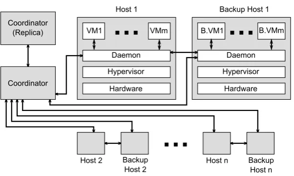
4.2. System Design. Our approach relies on two important features: automatic clustering of VMs and checkpointing/recovery coordination for VMs belonging to the same cluster. This entails the use of a coordinator component to manage these two processes. Moreover, another component is also needed on each machine to handle the checkpointing process for each VM, and to handle the communications with the coordinator component. The complete system design is displayed in Fig. 4.1, and the role of each component is given in the following.
4.2.1. The coordinator. The coordinator component has four different roles:
• Information gathering: it collects the information provided by the daemon component on each machine, which is necessary for the clustering process.
• Clustering: based on the collected information, VMs are grouped into different clusters. Then, the daemon component in each machine is informed about the clustering. This is necessary so that the daemon can differentiate between intra-cluster communications which can be immediately delivered, and communications to the OWP which have to be buffered.
• Recovery coordination: it manages the recovery process inside different clusters. This process is initiated by the daemon component after a failure.
4.2.2. The coordinator replica. This component is a substitute for the coordinator component. It is used after a failure of the coordinator component. It has two different roles:
• Replication of the coordinator: frequently enough, this component copies the information gathered by the coordinator. It also keeps a copy of the clustering state which is transmitted by the coordinator after the clustering process. The process for transmitting the clustering state to this component and to the daemon components is described further in this paper. This process ensures that the clustering information is consistent among all components even after the occurrence of a failure.
• Detection of the failure of the coordinator: using a heartbeat failure detection technique. Once the failure is detected, this component sends a message to all daemon components to inform them about the failure. Then, this component becomes the new coordinator, and another coordinator replica component is created on another machine.
4.2.3. The Daemon. This component runs on top of the hypervisor and provides host functionality for the checkpointing and the recovery processes. It is present in both the primary host and the backup host, and has the following roles:
• Probing: this component collects different information on VMs’ communications. These are transmit-ted to the coordinator component and are used during clustering process.
• Communication buffering: this component analyses outgoing VM’s communications and automat-ically buffers communications to the OWP. To do so, it associates a separate buffer for each VM.
• Checkpointing: this component supervises the checkpointing process for VMs on the host level. This includes checkpoint creation and checkpoint transmission to the backup host. Furthermore, this component should also communicate with the coordinator component and initiate the checkpointing process when asked to. It can also request a checkpoint creation for a cluster by sending a request to the coordinator. More details about the checkpointing process is given in Sect. 4.4.
• Failures detection: this component uses a heartbeat failure detection technique to detect a failure of the backup host or of the primary host. If a failure of the backup host is detected, then another backup host is selected and this component initiates a checkpointing process by sending a request to the coordinator component. If a failure of the main host is detected, then a recovery process is initiated by sending a request to the coordinator component. After the recovery, the backup host becomes the new primary host, and another backup host is assigned to the primary host. The recovery process is further described in this paper.
4.3. Dynamic Clustering. The dynamic clustering process consists on attributing a cluster for each VM being checkpointed. The objective during this process is to generate a set of clusters that reduces communication latencies and the overhead which is due to the checkpointing and the recovery process inside each cluster.
In the following, we first formalise the clustering problem and we give the cost function to optimise during the clustering. Then, we give a heuristic to solve the clustering problem. Finally, we describe the steps taken by the coordinator component during the clustering process which ensures that no inconsistent checkpoints are created even if the clustering configuration is changed.
4.3.1. Problem Definition and Cost Function. The clustering problem consists on attributing for a set of nVMsV ={vm0,vm1, . . . ,vmn}, a partitionC={c0, c1, . . . , cm}such that:
∪
ci∈C
=V and
ifci, cj∈ C andci ≠ cj thenci∩cj=∅
We associate for each cluster ci, a cost function f(ci) which is computed based on the checkpointing cost
of the cluster, notedh(ci), and the recovery cost of the cluster, notedr(ci). Such that:
f(ci) =h(ci) +r(ci) (4.1)
communication latencies are due to communications to the OWP which are buffered and only released after a checkpoint is taken. Moreover, every time communications are buffered, a communication-induced checkpoint is scheduled and taken to minimise communication latencies. As a consequence, communication latencies are directly correlated to the checkpointing frequency: the more often we take communication-induced checkpoints, the more often communications are retained and the more important are the induced communication latencies. Thus, by reducing the frequency of communication-induced checkpoints (i.e. the checkpointing cost), we also reduce communication latencies.
Accordingly, we define the cost function for a partitionC as follows:
F(C) = ∑
ci∈C
f(ci) (4.2)
We also define the optimum clustering as a partition C which minimises the cost function (4.2).
With regard to the checkpointing and the recovery costs for a clusterci, they are both computed based on
the time lost which is introduced by the checkpointing process on the VMs’ execution inside the cluster, and the time lost which is due to the recovery process. These two values are computed for a delay T which can be arbitrarily set.
The time lost due to the checkpointing process consists of the sum of the checkpointing overheads induced for each VM in the cluster during the chosen delayT. Assuming the checkpointing frequency for the clusterci
during the delayT isv(ci), and assumingδvmais the the checkpointing overhead corresponding to the VMvma, then:
h(ci) =v(ci)· ∑
vma∈ci
δvma (4.3)
Because the checkpointing process is coordinated for all VMs inside the cluster, the checkpointing fre-quency v(ci) corresponds to the highest VM checkpointing frequency in the cluster. Besides, checkpoints are
either initiated by the coordinator component given a frequency νvma for each VM vma, or by a daemon component after buffering communications. In such case, the checkpointing frequency is determined by the communication frequency of the VMs to the OWP.
We note µvma,vmb the communications frequency from vma to vmb during the delayT. Accordingly, we can estimate the checkpointing frequency for a clusterci as follows:
v(ci) = max vma∈ci
(
νvma, max
vmb∈C−ci
µvma,vmb
)
(4.4)
The time lost which is due to the recovery process can be estimated, for its part, knowing the failures frequency in the cluster. Assuming λ as the average failure frequency for a VM during the delay T, and assumingmthe number of VMs in the clusterci, the failure frequency for a clusterciduring the same delay is
thenm·λ.
After a failure in the cluster, all VMs in the cluster are rolled back to the previous checkpoint. Assuming that the failure happens on average at the middle way between two checkpoints, we can estimate the time lost due to a failure for each VM to be half the checkpointing interval. Thus, the time lost in the cluster after one recovery, which is the sum of time losses for each VM, can be computed as follows:
rsingle failure(ci) =m· T
2·v(ci)
(4.5)
Finally, we can estimate the time lost due to the recovery process as follows:
r(ci) =m2·λ· T
2·v(ci)
4.3.2. Heuristic for solving the clustering problem. The clustering problem is an instance of the set partitioning optimisation problem which has been proven to be NP-hard [3]. Thus, unlessP=N P, there is no algorithm that runs in polynomial time and brings an exact solution to the problem. However, it is possible to approximate the optimum solution using appropriate heuristics. In the following, we propose aO(n3) algorithm that uses a greedy strategy to solve the clustering problem (see Algorithm 1).
The proposed algorithm receives a list of VMs as input and generates a partition containing the clusters as output. It operates as follows. Firstly, it creates an initial partition where each VM is placed in its own cluster. Then it proceeds by stages in which clusters are merged two by two until no more clusters can be merged. In each stage, the algorithm computes the cost gain after merging two clusters by computing the difference between the cost induced by the clusters separately and the cost induced by the two clusters when merged. The two clusters that generate the highest cost difference if merged, are then combined.
Algorithm 1A greedy algorithm for the clustering problem
INPUT: Virtual MachinesV ={vm0,vm1, . . . ,vmn}
INPUT: The cost functionf() which computes the cost corresponding to a cluster as previously defined
OUTPUT: The partitionCofV which contains the clusters 1: ◃Initiate clusters
2: C ← ∅
3: for allvma∈ V do
4: C ← C ∪ {{vma}} 5: ◃Start merging clusters 6: repeat
7: toRemove ← ∅
8: merged ← ∅
9: a←0
10: for allci∈ C do
11: fi←f(ci)
12: for allcj∈ C − {ci} do
13: fj ←f(cj)
14: ft←f(ci∪cj)
15: d←(fi+fj)−ft ◃ Computes the cost gain
16: if d≥athen
17: a←d
18: toRemove ← {ci, cj}
19: merged ←ci∪cj
20: if toRemove̸=∅ then
21: C ←(C −toRemove)∪ {merged}
22: untiltoRemove=∅
23: returnC
4.3.3. Clustering process. The clustering process can be started at any moment during the lifetime of a VM by the coordinator component. Initially, each VM is attributed its own cluster. Next, after that enough information is gathered about the VMs’ communication profiles by the daemon components, a clustering process is engaged and another clustering configuration is defined. The clustering process can be started whenever important changes on the VMs’ communication profiles are detected.
The role of the clustering process is to ensure that the new clustering configuration is correctly transmitted to all daemon components and to the coordinator replica. Additionally, this process should not generate any inconsistencies with regard to the created checkpoints nor to the communications.
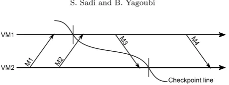
M2
M3 M4
VM1
VM2 M1
Checkpoint line
Fig. 4.2.Example of the state of the communication channels before, during and after checkpointing for two VMs
1. If there is any ongoing checkpointing or recovery process then wait for it to finish;
2. The coordinator component sends a message to all daemon components to pause the execution of all VMs;
3. Once all VMs are paused, the new clustering configuration is sent to all daemon components and to the coordinator replica component;
4. While the VMs are still paused, a checkpointing process is initiated for all new clusters;
5. Once all checkpoints have been taken, a message is sent to all daemon components to release buffered output to the OWP and to resume VMs’ execution.
4.4. Checkpointing process. The checkpointing process is coordinated among all VMs belonging to the same cluster. This process can be initiated in two different ways, either by the coordinator component, or after a request made by the daemon component. The coordinator component initiates the checkpointing process periodically according to a given frequency. The daemon component, for its part, requests to initiate the checkpointing process after buffering output for a VM.
Checkpoints requested by the daemon are communication-induced and have the same role as the forced checkpoints previously described in Sect. 3. They are initiated to minimise the packets retention delay in the buffer, and thus, to mitigate communication latencies to the OWP. As previously noted, these checkpoints should not be initiated immediately after communications are buffered. Instead, there must be a certain delay between the moment when communications are buffered, and the moment when the daemon component requests for a checkpoint. This delay can be computed using the same method described for our uncoordinated approach (cf. Eq. (3.3)).
After the checkpointing process is initiated for a given cluster, it is supervised by the coordinator component. This component requests a checkpoint for each VM in the cluster by sending a message to the appropriate daemon component. During this process, the coordinator must ensure that the resulting checkpoints define a consistent global snapshot [5].
In this context, there are many works in the literature that propose global snapshot algorithms [16, 14, 10]. These algorithms try to ensure two properties. First, a message issued by a VM which has already recorded its state (i.e. taken a checkpoint), should not be delivered to the destination VM until it has recorded its own state (e.g. M3 in Fig. 4.2). Secondly, after recording its state, a VM should also record all in-transit messages which were sent by other VMs before they recorded their own state (e.g. M2 in Fig. 4.2).
The first property is all the more important to guarantee a consistent state after recovering from a failure. This property ensures that if we have recorded a message reception in the checkpoint of a VM, then we also have recorded the corresponding message emission in the checkpoint of the VM that has sent the message [5]. Put differently, this also means that there is no recorded state (e.g. message reception) which depends on a future and un-recorded state (e.e. message emission).
The second property is necessary to avoid the loss of in-transit messages which can happen after recovering from a failure. This property is not critical when the communication channels are assumed unreliable. In such a case, a message loss which is due to a VM failure cannot be distinguished from a message loss which is due to a failure in communication channels. Hence, process level protocols (e.g. TCP) can be used to recover such messages if necessary.
occurrence of a failure, which is rather not frequent.
In our approach, the snapshot algorithm we use is a simplification of the existing Mattern’s algorithm [10]. We chose this algorithm because it is non-blocking and does not require FIFO communication channels. Our contribution consists on adapting this algorithm to our approach. In particular, we assume that the checkpoint-ing process can only be initiated by the coordinator component, and we allow the loss of in-transit messages.
In the following, we give a short description of the Mattern’s global snapshot algorithm. Then we describe our simplified version of this algorithm. Finally, we give our approach for coordinated checkpointing.
4.4.1. Overview of Mattern’s snapshot algorithm. This algorithm [10] is an extension of Chandy and Lamport’s snapshot algorithm [5] when non-FIFO communication channels are used. It can be used to create a consistent snapshot of a virtual cluster including the state of all communication channels (i.e. including in-transit messages). To this end, it uses a colouring principle in which a VM is either white or red. This colour is then piggybacked to all outgoing messages before they are sent to other VMs in the cluster.
Initially, the white colour is attributed to all VMs in the cluster. Any VM in the cluster can then initiate the global snapshot process. First, the initiator VM will take a local checkpoint and turn red. Next, it will send a control message to all other VMs in the cluster. Once a white VM receives the control message, it will take a local checkpoint and turn red in its turn.
In the meanwhile, the execution of VMs is not blocked and messages are continually exchanged. However, particular actions are taken when a white VM receives a red message, or when a red VM receives a white message.
First, if a white VM receives a red message, then the message is buffered and is only processed after the VM has turned red in its turn. This way, the first property which was previously discussed is guaranteed. Indeed, a message reception cannot be recorded in a checkpoint if the state that has generated it is not also recorded in a checkpoint.
Secondly, if a red VM receives a white message, then the message is identified as an in-transit message and is saved in the checkpoint as part of the state of the communication channels. To detect when there is no more in-transit messages, a counter is piggybacked in addition to the message’s colour in all exchanged messages. This way, after the termination of the snapshot algorithm, all in-transit messages are known and the previously discussed second property is satisfied.
4.4.2. Simplifications. We simplify the previous algorithm by discarding in-transit messages. In other words, we do not save white messages as part of the checkpoint when received by red VMs.
As a result, the snapshot algorithm can be terminated as soon as all VMs in the cluster turn red. Thus, we do not need to keep track of the count of transmitted/received messages nor do we need to transmit this information.
This simplification will induce the loss of in-transit messages after a failure. However, as previously stated, this does not cause any inconsistencies because we have assumed lossy communication channels.
4.4.3. Proposed approach. In our approach, we use the previously described simplified version of the Mattern’s algorithm [10] to make sure that the checkpoints created for VMs in a given cluster are globally consistent. Our contribution consists on defining a new approach based on this algorithm which, in addition to guaranteeing globally consistent checkpoints, also brings the following functionality:
• the management of errors during the creation of local checkpoints;
• the detection of the termination of the global snapshot algorithm;
• and the support for an output commit mechanism for communications to the OWP.
To achieve these goals, we rely on the cooperation of the coordinator component and the daemon component. For each component, we define a set of variables which are necessary for the checkpointing process to function, and a set of steps which are taken as part of the checkpointing process. These steps may involve the exchange of control messages between components, which is done using a failure-free communication protocol (e.g. TCP).
We detail these steps and the role of each component during the checkpointing process in the following.
No Yes
No Yes
Yes No Start
End flag = false?
number of VMs in the cluster cnt
Send checkpointing msgs to daemons
cnt - 1
cnt Send success
msgs to daemons timeout or error?
End cnt = 0?
true flag
false flag
Send error msgs to daemons Wait for an ACK
msg from daemons
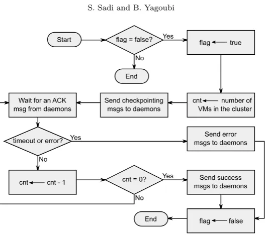
Fig. 4.3. Flow chart displaying the checkpointing process steps taken by the coordinator component for a cluster
only one checkpointing process is active for the same cluster at the same moment. To identify a cluster, the coordinator component relies on the unique identifier which was assigned to it during the clustering process.
The steps taken by the coordinator component during the checkpointing process are displayed in Fig. 4.3. During these, the coordinator first sends a control message to all daemon components corresponding to the VMs in the current cluster asking them to initiate the checkpointing process locally. Then the coordinator component waits for acknowledgement messages or error messages. When the coordinator receives the same number of acknowledgement messages as the number of VMs in the cluster, it can assert that all VMs in the cluster have been checkpointed and a success termination message is sent to all daemon components in the cluster. Otherwise, if the coordinator receives an error message, or if, after a given delay, the coordinator does not receive all acknowledgement messages, then an error is assumed and an error termination message is sent to all daemon components in the cluster.
The daemon component. It manages the checkpointing process at the host level. One or multiple VMs may be checkpointed at the same moment without interfering. To this extent, this component keeps a separate dataset per VM which includes the following:
• the cluster identifier of the VM;
• the corresponding backup host where the VM’s checkpoint is saved;
• the communications’ buffer, which is used to store outgoing communication packets before they are released to the OWP;
• the epoch value which is associated to the communications’ buffer and is used to determine when packets are released to the OWP;
• the colour of the VM, which is necessary for the global snapshot algorithm to function;
• another communications’ buffer, which is used during the checkpointing process when a white VM receives red communication packets.
By default, all outgoing communications of a VM to the OWP are buffered. Communications of VMs inside the same cluster are not suspended. However, the colour of the sending VM is piggybacked to each communication packet before it is transmitted to another VM in the same cluster. This can be achieved transparently through network virtualisation (e.g. using Violin [12]).
Yes
No Yes
No
Start Wait for the
checkpointing msg
More VMs?
Select VMs in the given cluster Select next VM
Initiate local checkpoint for the VM
Wait for the termination message
success?
Set the white color for VMs in the cluster Discard the created
local checkpoints
Release buffered output to the OWP
End
Validate the created local checkpoints
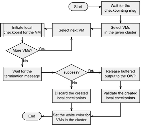
Fig. 4.4.Flow chart displaying the checkpointing process steps taken by the daemon component for a cluster
After that a checkpoint is initiated for a given cluster, the daemon component will concurrently create a local checkpoint for each VM in the current host which belongs to the cluster being checkpointed.
The steps which are globally taken (for all VMs in the current host and current cluster) by the daemon component are displayed in Fig. 4.4. They mainly consist on initiating the local checkpoint creation for all VMs in the current cluster, and to wait for the termination message from the coordinator component. If the daemon component receives a success termination message, then it validates all created checkpoints and, for each VM in the current cluster, it releases any buffered output since last epoch to the OWP. However, if an error termination message is received, then the local checkpointing process is aborted and all checkpoints resulting from the current process are discarded.
The steps taken for each VM by the daemon component are displayed in Fig. 4.5. First the daemon component pauses the VM, creates the checkpoint file and updates the colour and the epoch associated with the VM. Next, the VM is resumed and, because the VM is now red, any incoming red message which was previously buffered is released. Finally, the checkpoint file is transmitted to the backup host, and either an acknowledgement message or an error message is transmitted to the coordinator component.
4.5. Recovery process. The recovery process is managed by the coordinator component inside each cluster. This process is initiated after that a failure is detected by a daemon component, and that a request is formulated and sent to the coordinator component.
Once the recovery process is initiated for a given cluster, no further checkpointing is possible for the cluster until the recovery process is finished. However, if the coordinator process is already engaged in a checkpointing process while receiving a recovery request, then the checkpointing process is first aborted before initiating the recovery process. This has the same consequences as if an error was reported by a daemon component during the checkpointing process.
The steps taken by the coordinator component during the recovery process are the same as those taken during the checkpointing process (cf. Fig. 4.3) with two notable differences. Firstly, a recovery message is sent to the daemon components instead of a checkpointing message. Secondly, the recovery message is sent to the daemon components corresponding to the secondary VMs (i.e. backup VMs) in the current cluster, and not to the daemon components corresponding to the primary VMs.
No Yes
Start Pause VM
Create the VM checkpoint
Send checkpoint file to the backup host
End
epoch+1 epoch
red color
Release buffered red messages
success? Send ACK message
to the coordinator Resume VM
Send error message to the coordinator
Fig. 4.5.Flow chart displaying the checkpointing process steps taken by the daemon component for a single VM
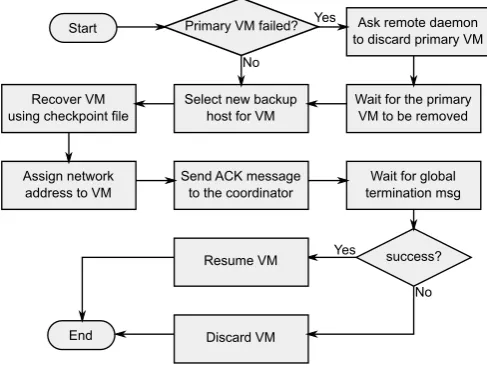
No Start
Select new backup host for VM
End
Ask remote daemon to discard primary VM Primary VM failed?
Discard VM Assign network
address to VM Recover VM using checkpoint file
Send ACK message to the coordinator
Yes
Resume VM
Wait for global termination msg
success? Yes
Wait for the primary VM to be removed
No
Fig. 4.6.Flow chart displaying the steps taken by the daemon component when recovering a single VM
all VMs in the current cluster for which it has a saved checkpoint. This process is illustrated in Fig. 4.6. For each VM, the daemon component will use the backup host as its new primary host and another backup host is selected for the VM. This way, the checkpoint file is immediately available for recovery, and there is no need to transmit the checkpoint file through the network.
With regard to the old primary VM, if it has not failed, then a message is sent to the corresponding daemon component to discard the VM and any related state (i.e. communication buffers). The network address of the VM is then reattributed to the new VM that results from the recovery process.
After that the old primary VM is discarded, and after that the new VM has been recovered using the checkpoint file, an acknowledgement message is sent to the coordinator component. However, the recovered VM is not immediately started. This guarantees that the recovered VM is not affected by other running (and not yet recovered) VMs in the cluster, which, in turn, guarantees a consistent global state for the cluster after recovery.
error happens, then the cluster is put under an erroneous state and any previously recovered VM is discarded. The coordinator component can then initiate another recovery of the cluster if necessary.
5. Evaluation. In this section, we present the performance measurements of the two approaches presented in this paper. To this extent, we have simulated and compared both the presented approaches, and three other state-of-the-art approaches: one uncoordinated (Remus [6]) and two coordinated (VCCP [21] and VNSnap [13]). The simulations were performed using the ACS [22] simulator. ACS is an open source discrete event simulator which enables Cloud Computing simulation and performance evaluation of different aspects of the Cloud. Our choice for ACS has been motivated by two points. First, it already implements many aspects of fault tolerance simulation, which greatly reduces implementation efforts. Secondly, it offers high performance simulations both in terms of memory consumption and simulation time.
During the simulations, we have focused on three different measures to evaluate the performances of a given approach. The first and the second measures are, respectively, the average communications’ latency and the percentage of packets loss during communications. These two values are used to evaluate the communications’ handling aspect of the simulated approaches. The third measure is the added execution time of submitted jobs relatively to their initial length. The extra-time is due to the checkpointing process and the failures. It is a good indicator of an approach’s ability to introduce low overheads during the checkpointing process and the recovery process.
In the following, we first start by describing the different values that were used as simulation input. Next, we compare simulated approaches based on the previously described communication measures. Finally, we compare simulated approaches based on the added overhead on the jobs’ execution time.
5.1. Simulation input. There are many simulation inputs that can interfere with the checkpointing and the recovery processes, and consequently, with a VM’s execution. For each of these inputs, we need to cover the largest possible set of values during the simulations to draw trustworthy conclusions on the performances of a given approach.
However, the number of simulations per approach grows rapidly as the number of tested inputs grows. Therefore, to limit the number of simulations, it is necessary to limit the values tested for each input. To this extent, we use empirical data, when available, to set input values. For other inputs, we try to chose the most representative values.
5.1.1. Single-valued simulation inputs. The values of these inputs are set based on empirical data. We define one unique value for each of them and for all simulations. These inputs include: the average job length, the checkpointing overhead, the recovery overhead and the average networks links latency.
The job length is randomly generated based on a mean value of 100 hours. At first glance, this value may seem too high. However, it allows us to emphasise the efficiency of each approach. Besides, since all tested approaches use VM-level checkpointing, and considering the fact that a VM’s lifetime can be relatively high, this allows us to simplify the simulations by assigning exactly one job per VM.
The checkpointing overhead is also randomly generated based on empirical data. It defines the checkpoint file creation delay (randomly chosen using a mean value of 200 milliseconds), the checkpoint file size (randomly chosen using a mean value of 30MiB) and the available bandwidth for transferring the checkpoint (set to 100MiB/s).
The recovery overhead defines the delay for recovering a VM using a checkpoint file. It is randomly chosen based on a mean value of 300 milliseconds. We assume that the host where the checkpoint file is located is the same host that is used when recovering a VM. This is the behaviour that has been defined by Remus and our approaches. Other tested approaches do not give explicit directives on this matter.
The network link latency is the average latency for message communications when no checkpointing approach is used. This value is randomly chosen for each communication based on a mean value of 10 milliseconds which is commonly observed in medium to large-scale data centres.
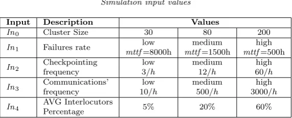
5.1.2. Multi-valued simulation inputs. Added to the previous inputs, we define five other inputs which take three different values each (cf. Table 5.1).
Table 5.1
Simulation input values
Input Description Values
In0 Cluster Size 30 80 200
In1 Failures rate low
mttf=8000h
medium mttf=1500h
high mttf=500h
In2 Checkpointing frequency
low 3/h
medium 12/h
high 60/h
In3 Communications’ frequency
low 10/h
medium 500/h
high 3000/h
In4 AVG Interlocutors
Percentage 5% 20% 60%
The failures rate (notedIn1) defines the number of failures generated per host. Each failure rate corresponds to a mean time to failure value (MTTF). This value is used during the simulations to randomly generate failures following an exponential distribution.
The checkpointing frequency (notedIn2) defines the average number of checkpoints taken for each VM in a given period of time. The values presented in Table 5.1 are the average values, and the final checkpointing frequency for each VM is randomly chosen given that average.
The communications frequency (notedIn3) defines the average number of communication messages sent by a VM during a given period of time. This is also an average value, and final values are randomly set during the simulation.
Finally, the average interlocutors percentage (noted In4) is used to define the number of remote VMs that a given VM can communicate with during the simulation. This percentage is relative to the number of VMs initially submitted.
5.1.3. Other considerations on simulation input. The VCCP and the VNSnap approaches do not take into account communications to the OWP. Consequently, when using these approaches, we have assumed that all VMs belong to the same cluster and that no communications to the OWP are possible.
For our coordinated approach, we assumed that communication profiles are already available when the sim-ulation starts. Consequently, the VMs are automatically grouped into different clusters during the initialisation of the simulation.
With regard to the number of simulations, it can be computed after generating all possible values combi-nations for simulation inputs. This results in a total of 1215 simulations, which corresponds to 243 simulations per approach.
During the simulations, we have assumed that there is always a sufficient number of machines for hosting the VMs and their backups. The VMs are initially placed using a random-fit placement policy given a fixed set of available hosts. Then, each time a new host is needed, the same policy is used again.
Regarding number generation, we use the same random seed for all simulations. Thus, given the same input, same random values are generated and we can guarantee the correctness of results when comparing two approaches.
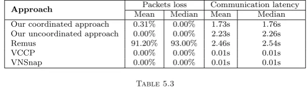
5.2. Evaluation of communication latencies and packets loss. Simulation results regarding packets loss and communication latencies are summarised in Table 5.2. The mean and median values displayed in this table, have been computed for each approach after all simulations.
Over the 1215 simulations, the VCCP and VNSnap approaches were the most efficient in terms of commu-nication latencies and packets loss. The reason for that, is that these approaches do not take into account com-munications to the OWP. Consequently, communication packets do need to be retained and no extra-latencies are induced.
The next most efficient approach is our coordinated approach. This approach introduced a relatively small network latency and a negligible rate of packets loss which is mostly due to the recovery process.
Table 5.2
Summarised simulations results for communication latencies and communication packets loss
Approach Packets loss Communication latency
Mean Median Mean Median Our coordinated approach 0.31% 0.00% 1.73s 1.76s Our uncoordinated approach 0.00% 0.00% 2.23s 2.26s
Remus 91.20% 93.00% 2.46s 2.54s
VCCP 0.00% 0.00% 0.01s 0.01s
VNSnap 0.00% 0.00% 0.01s 0.01s
Table 5.3
Correlation coefficients of simulation input with communication packets loss
Approach In0 In1 In2 In3 In4
Our coordinated approach 0.04 0.00 -0.08 0.00 0.26 Our uncoordinated approach 0.00 0.00 0.00 0.00 0.00
Remus -0.20 0.00 -0.87 0.00 0.00
VCCP 0.00 0.00 0.00 0.00 0.00
VNSnap 0.00 0.00 0.00 0.00 0.00
Remus induced the highest rate of packets loss and caused high messages latency. The packets loss was due to communication timeouts. This was predictable as Remus retains outgoing communications until a checkpoint is committed, and it does not implement any strategy to reduce communication latencies.
5.2.1. Correlation with simulation input. We have used the Pearson product-moment correlation coefficient (PPMCC) to measure the correlation of simulation input with the communications’ packets loss rate, and with the communication latencies.
The PPMCC is used in statistics as a measure of linear correlation between two variables. It takes its values in the range −1· · ·+ 1, where +1 indicates a perfect correlation, 0 indicates no correlation and −1 a total negative correlation.
The PPMCC values corresponding to the rate of communication packets loss are displayed in Table 5.3, and the PPMCC values corresponding to communication latencies are displayed in Table 5.4.
With regard to the rate of communication packets loss, we see no important correlation with any of the inputs when using an approach other than Remus.
For Remus, there is an non-negligible negative correlation of the rate of communication packets loss with the checkpointing frequency (In2). This is due to the fact that Remus releases output for a VM only after a checkpoint is committed. Thus, a more frequent checkpointing induces lower output retention delays, which in turn induces lower communication latencies. Consequently, there is a lower rate of packets loss which is due to communication timeouts.
With regard to communication latencies, we see an important negative correlation with the checkpointing frequency (In2) for Remus, and with the communications’ frequency (In3) for our approaches.
The correlation of communication latencies with the checkpointing frequency when using Remus has already been discussed, and is due to the fact that Remus releases network output only after a checkpoint is committed. For our approaches, the correlation of communication latencies with the communications’ frequency is due to the fact that the checkpointing frequency is in part determined by the communications’ frequency. In fact, a communication-induced checkpoint is scheduled each time network output is buffered. Thus, by increasing the communications’ frequency, we also increase the checkpointing frequency, and we reduce the retention delay of network output.
5.3. Evaluation of jobs’ execution time. For each simulation, we have computed the average jobs’ completion time for all VMs. This value was then used to compute the added execution time which is due to the checkpointing process and the failures, based on the average jobs’ length when the simulation was initialised. Finally, we have estimated the percentage of added execution time for each simulation.
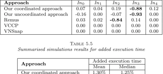
Table 5.4
Correlation coefficients of simulation input with communication latencies
Approach In0 In1 In2 In3 In4
Our coordinated approach 0.07 0.04 0.19 -0.88 0.12 Our uncoordinated approach -0.16 0.00 -0.07 -0.93 0.00
Remus 0.03 0.02 -0.84 0.14 0.00
VCCP 0.00 0.00 0.00 0.00 0.00
VNSnap 0.00 0.00 0.00 0.00 0.00
Table 5.5
Summarised simulations results for added execution time
Approach Added execution time
Mean Median Our coordinated approach 1.30% 1.25% Our uncoordinated approach 1.51% 1.44%
Remus 0.22% 0.12%
VCCP 6.94% 6.15%
VNSnap 1.76% 1.77%
Over the 1215 simulations, Remus offered the best value for the average job completion time. This is due to two reasons. First, Remus does not take forced communication-induced checkpoints as we do in our approaches. Secondly, Remus does not assume any clustering for checkpointed VMs. Thus, it does not induce any extra-overhead to orchestrate the checkpointing or the recovery process inside a cluster. Moreover, failures are less costly. In fact, when using Remus, only the failed VM needs to be recovered. Conversely, when using a coordinated approach, all VMs belonging to the same cluster have to be recovered each time a VM in the cluster fails.
The second most efficient approach is our coordinated approach. This approach ensures that an appropriate clustering of VMs is done to minimise the execution time of VMs. However, the frequent communication-induced checkpoints causes extra-overhead which makes it less efficient than Remus when considering execution time.
Our uncoordinated approach was the next most efficient approach. This approach, as for Remus, does not induce extra-overhead to orchestrate the checkpointing or the recovery process inside a cluster.
VNSnap is the fourth most efficient approach. It performed worse than previous approaches because the checkpointing process needs to be orchestrated over all submitted VMs. Additionally, each time a failure happens, all VMs need to be recovered.
VCCP was the worse performing approach. Added to the disadvantages of VNSnap on the execution time of VMs, this approach also uses a blocking checkpointing process which highly burdens the VMs’ execution.
5.3.1. Correlation with simulation input. As for packets loss and communications’ latency, we have used the PPMCC values to estimate the correlation of execution time with simulation input. The coefficients are displayed in Table 5.6.
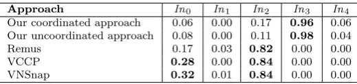
For our approaches, we see an important correlation of execution time with the communications’ frequency (In3). This correlation can be anticipated because the communications’ frequency determines the number of communication-induced checkpoints taken when using our approaches, and a high number of checkpoints induces a high overhead on the execution time. Additionally, the low correlation with the checkpointing frequency (In2). indicates that most of the checkpoints taken by our approaches are communication-induced.
For Remus, VCCP and VNSnap, there is a high correlation of execution time with the checkpointing frequency (In2). This is predictable as more frequent checkpointing induces a higher overhead on the execution of the VMs.
Besides, we see a non-negligible correlation of execution time with the number of submitted VMs (In0) when using VCCP and VNSnap. This can be explained by the fact that, the checkpointing and recovery processes are more costly as the cluster size is bigger.
Table 5.6
Correlation coefficients of simulation input with the added execution time
Approach In0 In1 In2 In3 In4
Our coordinated approach 0.06 0.00 0.17 0.96 0.06 Our uncoordinated approach 0.08 0.00 0.11 0.98 0.04
Remus 0.17 0.03 0.82 0.00 0.00
VCCP 0.28 0.00 0.84 0.00 0.00
VNSnap 0.32 0.01 0.84 0.00 0.00
strive to keep a consistent view of checkpointed VMs from the outside world process. This is achieved by using an output commit mechanism which buffers communications until a checkpoint is committed. Our main contribution in this matter was to define a process for taking forced communication-induced checkpoints to re-duce the retention delay of buffered communications. Additionally, we also defined a non-blocking coordinated checkpointing approach, which automatically groups VMs into clusters to reduce inter-VM communication latencies.
The comparison of the two proposed approaches with state of the art approaches (Remus, VCCP and VNSnap) shows that our coordinated approach is the best performing approach when considering both the exe-cution time of the VMs and the communication latencies. Our uncoordinated approach, is next best performing approach when considering those two metrics.
When considering the execution time, Remus was better. However, the packets loss rate is excessively important.
When considering communication latencies, VCCP and VNSnap were better. However, these two ap-proaches do not take into account communications to the outside world process. Thus, they are unusable in a Cloud environment if the consistency of the VMs’ execution towards the outside world process is an issue.
Finally, as future work, we aim to implement the two proposed approaches on top of the Xen hypervisor to evaluate their efficiency and feasibility on a real Cloud environment.
REFERENCES
[1] S. Agarwal, R. Garg, M. S. Gupta, and J. E. Moreira,Adaptive incremental checkpointing for massively parallel systems, in Proceedings of the 18th annual international conference on Supercomputing, ACM, 2004, pp. 277–286.
[2] M. Armbrust, A. Fox, R. Griffith, A. D. Joseph, R. Katz, A. Konwinski, G. Lee, D. Patterson, A. Rabkin, I. Stoica, et al.,A view of cloud computing, Communications of the ACM, 53 (2010), pp. 50–58.
[3] E. Balas and M. W. Padberg,Set partitioning: A survey, SIAM review, 18 (1976), pp. 710–760.
[4] K. Chanchio, C. Leangsuksun, H. Ong, V. Ratanasamoot, and A. Shafi,An efficient virtual machine checkpointing mechanism for hypervisor-based hpc systems, in High Availability and Performance Computing Workshop, 2008. [5] K. M. Chandy and L. Lamport,Distributed snapshots: determining global states of distributed systems, ACM Transactions
on Computer Systems (TOCS), 3 (1985), pp. 63–75.
[6] B. Cully, G. Lefebvre, D. Meyer, M. Feeley, N. Hutchinson, and A. Warfield,Remus: High availability via asyn-chronous virtual machine replication, in Proceedings of the 5th USENIX Symposium on Networked Systems Design and Implementation, San Francisco, 2008, pp. 161–174.
[7] I. P. Egwutuoha, D. Levy, B. Selic, and S. Chen,A survey of fault tolerance mechanisms and checkpoint/restart imple-mentations for high performance computing systems, The Journal of Supercomputing, 65 (2013), pp. 1302–1326. [8] E. N. Elnozahy, L. Alvisi, Y.-M. Wang, and D. B. Johnson,A survey of rollback-recovery protocols in message-passing
systems, ACM Computing Surveys (CSUR), 34 (2002), pp. 375–408.
[9] K. B. Ferreira, R. Riesen, P. Bridges, D. Arnold, and R. Brightwell, Accelerating incremental checkpointing for extreme-scale computing, Future Generation Computer Systems, 30 (2014), pp. 66–77.
[10] R. Garg, V. K. Garg, and Y. Sabharwal,Scalable algorithms for global snapshots in distributed systems, in Proceedings of the 20th annual international conference on Supercomputing, ACM, 2006, pp. 269–277.
[11] D. Ibtesham, D. Arnold, K. B. Ferreira, and P. G. Bridges,On the viability of checkpoint compression for extreme scale fault tolerance, in Euro-Par 2011: Parallel Processing Workshops, Springer, 2012, pp. 302–311.
[12] X. Jiang and D. Xu,Violin: Virtual internetworking on overlay infrastructure, in Parallel and Distributed Processing and Applications, Springer, 2005, pp. 937–946.
[13] A. Kangarlou, P. Eugster, and D. Xu, Vnsnap: Taking snapshots of virtual networked infrastructures in the cloud, Services Computing, IEEE Transactions on, 5 (2012), pp. 484–496.
[15] A. Litvinova, C. Engelmann, and S. L. Scott,A proactive fault tolerance framework for high-performance computing, in Proceedings of the 9th IASTED International Conference, vol. 676, 2009, p. 105.
[16] F. Mattern,Efficient algorithms for distributed snapshots and global virtual time approximation, Journal of Parallel and Distributed Computing, 18 (1993), pp. 423–434.
[17] P. Mell and T. Grance,The nist definition of cloud computing, National Institute of Standards and Technology, 53 (2009), p. 50.
[18] B. Meroufel and G. Belalem, Adaptive time-based coordinated checkpointing for cloud computing workflows, Scalable Computing: Practice and Experience, 15 (2014).
[19] J. Nakano, P. Montesinos, K. Gharachorloo, and J. Torrellas,Revivei/o: Efficient handling of i/o in highly-available rollback-recovery servers, in High-Performance Computer Architecture, 2006. The Twelfth International Symposium on, IEEE, 2006, pp. 200–211.
[20] B. Nicolae and F. Cappello,Blobcr: efficient checkpoint-restart for hpc applications on iaas clouds using virtual disk image snapshots, in Proceedings of 2011 International Conference for High Performance Computing, Networking, Storage and Analysis, ACM, 2011, p. 34.
[21] H. Ong, N. Saragol, K. Chanchio, and C. Leangsuksun, Vccp: A transparent, coordinated checkpointing system for virtualization-based cluster computing, in Cluster Computing and Workshops, 2009. CLUSTER’09. IEEE International Conference on, IEEE, 2009, pp. 1–10.
[22] S. Sadi and B. Yagoubi,Acs-advanced cloud simulator: A discrete event based simulator for cloud computing environments, in Proceedings of the 2nd International Conference on Networking and Advanced Systems, 2015, pp. 11–16.
[23] S. Sadi and B. Yagoubi,On the optimum checkpointing interval selection for variable size checkpoint dumps, in Computer Science and Its Applications, Springer, 2015, pp. 599–610.
[24] K. V. Vishwanath and N. Nagappan,Characterizing cloud computing hardware reliability, in Proceedings of the 1st ACM symposium on Cloud computing, ACM, 2010, pp. 193–204.
[25] L. Wang, Z. Kalbarczyk, R. K. Iyer, and A. Iyengar,Vm-µcheckpoint: Design, modeling, and assessment of lightweight in-memory vm checkpointing, Dependable and Secure Computing, IEEE Transactions on, 12 (2015), pp. 243–255. [26] J. W. Young,A first order approximation to the optimum checkpoint interval, Communications of the ACM, 17 (1974),
pp. 530–531.
Edited by: Dana Petcu
Received: Apr 17, 2016
![Fig. 3.2. Time diagram displaying the output commit mechanism used by Remus [6]](https://thumb-us.123doks.com/thumbv2/123dok_us/8745894.1747306/4.595.177.421.109.198/fig-time-diagram-displaying-output-commit-mechanism-remus.webp)