Available Online at www.ijpret.com 344
INTERNATIONAL JOURNAL OF PURE AND
APPLIED RESEARCH IN ENGINEERING AND
TECHNOLOGY
A PATH FOR HORIZING YOUR INNOVATIVE WORK
DESIGN AND PERFORMANCE ANALYSIS OF SINGLE INLET MULTIPLE OUTLET JET
NOZZLE ALONG WITH THRUST CONTROLLER
P. YUVARAJ, S. MURALI SANKAR
Assistant Professor, Department of Mechanical Engineering, Apollo Engineering College, Chennai.
Accepted Date: 22/11/2014; Published Date: 01/12/2014
\
Abstract: Today, thrust vectoring has become a very important research subject which can
dramatically change the way aircraft maneuver and its performance. This paper tries to present a unique approach to this topic by highlighting a concept defined as Single Inlet Multiple Outlet (SIMO) in detail. This can be explained by having multiple nozzles for exhaust purpose than those conventional one or two nozzles as we know of presently. This idea may yet not be able to apply directly to VTOL (Vertical Takeoff & Landing), but can be applied very well to change thrust direction of the aircraft effectively including thrust reversal and hence reducing the dependability on the primary control surface to great extent. These nozzles can be made to work in tandem with primary control surfaces so that, in case of failure of primary control surfaces occur, the aircraft can still be maneuvered and saved thereby avoiding loss of millions of dollar worth of property, aircraft and most important pilot’s life.
Keywords: Sisal fiber, Epoxy resin, Treated and Untreated fiber, mechanical testing, weight
percentage
Corresponding Author: MR. P. YUVARAJ
Access Online On:
www.ijpret.com
How to Cite This Article:
P Yuvaraj, IJPRET, 2014; Volume 3 (4): 344-354
Available Online at www.ijpret.com 345 INTRODUCTION
In present day aircrafts, power plants constitute the lifeline of the plane and for military aircrafts; power plant has become more significant since it is the one which provides the aircraft of almost all its performance characteristics. Nozzle is a very significant part of the aircraft engine and which not only propels the aircraft but now even can assist the aircraft in performing maneuvers, TVC Nozzles used in JSF-Joint Strike Fighter, USA; Sukhoi 30MKI, India to name a few. The above stated aircrafts use advanced nozzle technology called THRUST VECTOR CONTROL. Present day aircrafts currently employ one nozzle per engine. This paper presents a new concept called SIMO (Single Inlet Multiple Outlet) which employ five nozzles instead of one nozzle to single engine. With four of these five nozzles equipped with thrust vector control, we can achieve all directional control of the aircraft thus reducing our dependence on the control surfaces. This paper discusses the following aspects concerned with this concept.
1. Thrust Vectoring
2. SIMO Arrangement
3. Mechanism
4. Aerodynamic Effects
5. Engine Thrust Aspects
6. Loss Analysis
7. Possible Applications
8. Limitations
9. Conclusions
Thrust Vectoring
Available Online at www.ijpret.com 346
effect of thrust vector control employed in US F-22 Raptor which can vector its thrust up to 20° about its vertical plane.
Fig.1 F-22 without TVC ability
In TVC, the nozzle of the aircraft engine is tilted in order to produce a vectored thrust with respect to the center line of the aircraft. Few aircrafts like MiG-29, F-16 etc use two nozzles to expand the combustion product and both the nozzles are equipped with TVC.
SIMO Arrangement
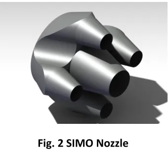
In general aircraft jet engines have nozzle which have one inlet and one outlet whereas the SIMO nozzle is having one inlet and five outlets. Fig.2 shows an isometric conceptual model of SIMO.
Fig. 2 SIMO Nozzle
Available Online at www.ijpret.com 347
The secondary outlets are equipped with thrust vectoring system. The arrangement of the secondary outlets will be in Diamond Formation around the primary outlet. This secondary outletcluster is in diamond formation rather than in rectangular formation so as to avoid over heating of secondary outlet walls during the deflection of the secondary outlets. In rectangular formation, performing yaw and pitching maneuvers will lead exhaust from the two secondary outlets almost directly heating the other two adjacent secondary outlet walls.
In diamond (rhombus shape) arrangement of the secondary outlet system they are located around the primary outlet shape in a rhombus formation. During any maneuver, pitching or yawing the exhaust from the any one secondary outlet will lead to the heating of the outer primary outlet wall whole throughout. Therefore, the cooling of the outer wall of the primary nozzle wall is of prime importance and will be discussed further later in the paper. The secondary outlets in horizontal plane will work like elevon control in military aircrafts. That is, both the outlets will move in same direction and also in different direction.
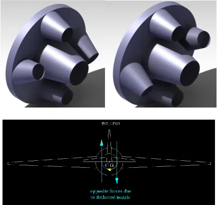
Fig.3 Rectangular Rhombus
Both the diamond and rectangular arrangement of the secondary nozzle arrangement is shown in the diagrams above.
Mechanism
Available Online at www.ijpret.com 348
This SIMO concept can very well be applied to perform any aircraft maneuver. Following are the diagrams (Fig.5,6,7) which illustrate the movement of secondary nozzles to perform basic aircraft maneuvers i.e. Pitch, Yaw, Roll respectively.
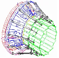
Fig. 4 Typical 3-D Nozzle Actuation System
Fig.6 shows the pitch motion (nose up and down) of an aircraft is achieved by actuating the two outlets, placed in horizontal plane, similarly about the same plane. The creation of torque is shown in next figure.
Fig. 6 Pitch Motion
Available Online at www.ijpret.com 349 Fig.7 Yaw Motion
Fig.8 shows the Roll motion of an aircraft which is achieved by actuating the horizontal plane outlets in different directions about the same plane. When one outlet goes up the other goes down.
Fig.8 Roll Motion
Aerodynamic Effects
The aerodynamic characteristics of the aircraft will not be affected much as the nozzles are perfectly streamlined to reduce any aerodynamic losses due to drag and other factors.
Available Online at www.ijpret.com 350 Fig.9 Pressure
Fig.10 Temperature
Fig.11 Velocity
Fig.12 SIMO: Grid & Velocity
Fig.13 Static and Total Pressure
Fig.14 Static and Total Temperature
Available Online at www.ijpret.com 351
aerodynamic aspects of the nozzle will be same as that of the conventional nozzle systems used in other aircrafts.
Loss Analysis
The losses will be mainly due to the vectored thrust arrangement. The velocity vector in the direction (in case of downward component of velocity) the component will be V2*COS α where α being the angle of the vectored thrust or the angle by which the secondary nozzles will change tilt or shift.
The loss in this case will be V2 – V2COS α
Where,
V1 = Inlet velocity in the nozzle before expansion in the nozzle
V2 = Outlet velocity in the nozzle after expansion in the nozzle.
This loss will be compounded in the form of four secondary nozzles. So the total losses can be found as to be
L = 4 * (V2 – V2 COS α)
This loss can be minimized reducing the angle α by reducing this angle we can control the losses in this nozzle system. The angle α can be effectively reduced as for an angle we have four corresponding secondary nozzles, each of which will generate an equal amount of thrust in the required direction.
Thrust loss
While analyzing the velocity counters for both convergent and SIMO nozzle, it is clear that about 21% of loss occurs at the exit velocity. That is, a loss of 21% in thrust is occurring while employing the SIMO nozzle instead of conventional nozzle. This loss can be unadjusted by the added advantages of SIMO which will be described later in this paper. The fighter aircrafts generally employed with engine with excess thrust therefore this arrangement will not affect the required thrust.
Engine Thrust Aspects
Available Online at www.ijpret.com 352
thrust in combat situations enabled an aircraft to perform various maneuvers not available to conventional-engine planes. Most currently operational vectored thrust aircraft use turbofans with rotating nozzles or vanes to deflect the exhaust stream. This method can successfully deflect thrust through as much as 90 degrees, relative to the aircraft centerline. However, the engine must be sized for vertical lift, rather than normal flight, which results in a weight penalty. Afterburning (or Plenum Chamber Burning in the bypass stream) is difficult to incorporate and is not practical for Take-off/Landing, because the very hot exhaust leaves scorch marks on the ground. Without afterburning it is difficult to reach supersonic flight speeds. A fluidic nozzle diverts the thrust via fluid effects Given below is a diagram to explain as to how this nozzle system will help to get change in direction of the aircraft using engine thrust.
As we can see in the diagram shown below, the horizontal velocity component is due to Primary Nozzle and the far oblique velocity going extreme downward is the Secondary Nozzle velocity component (due to the vectoring of the upper and two side secondary outlets in the upper direction with the required angularity).
Fig. 15 Resultant Motion
Available Online at www.ijpret.com 353
The primary outlet will account for 40% of the thrust generated by the engine. The rest 60% of the engine thrust is divided among the secondary outlets with thrust vectoring capability. This 60% of the thrust is divided into 15% in each of the secondary outlets to achieve reasonable engine performance with appropriate expansion of the gases coming out of the combustion chamber. The thrust to weight ratio of the aircraft installed with this kind of thrust vectoring capability can be adjusted to acceptable range by reducing the wing aspect ratio to a minimum with reduced dependability on the primary control surfaces. These control surfaces can complement this nozzle system in performing the necessary maneuvers. This kind of arrangement between the nozzle system and the control surfaces gives the aircraft an extremely high degree of maneuverability and make it very competitive in air dogfights.
Cooling
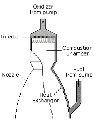
The cooling of the primary outlet due to the vectoring of the secondary outlet is taken care of by having an effective cooling system in place for the primary nozzle. Of all the cooling systems available regenerative cooling is the most effective method of cooling the primary outlet wall. This will increase the reusability of the primary outlet and thereby reduce the cost as well. The regenerative cooling is done by building a cooling jacket around the nozzle and circulating the fuel through it before it is fed to the injector. The heat is taken away by way of cooling is picked up by the fuel and fed back to the combustion chamber, so it is not lost. It’s quite an effective method in applications with high chamber pressure and high heat transfer rates. Fig.10 shows the schematic diagram of regenerative cooling system.
.
Fig. 16 Regenerative Cooling System
Available Online at www.ijpret.com 354 CONCLUSION
The SIMO concept is well studied for dog fighting in military aircrafts. This can be applied very well to change the thrust direction of the aircraft and hence educing the dependability on the control surface to great extent. These nozzles can be made to work in tandem with primary control surfaces so that in case of failure of control surface occur, the aircraft can still be maneuvered and saved. Though this nozzle design is having considerable efficiency losses, the high degree of maneuverability by this nozzle adds sense to its implementation.
REFERENCES
1. Thrust Vectoring Nozzlefor Modern Military Aircraft by DanielI kaza, Industria de Turbo Propulsores S.A. (ITP), Spain.
2. STOL Aircraft Design for Undergraduates, Russell M Cummings, David W Hall.
3. Nozzle of air breathing engines, V.B.Rutovskii – Mascow state aviation institute, Russia.
4. Highlights of the JSF X-35 STOVL Jet Effects Test Effort, Mark D Buchholz; Lockheed Martin Aeronautics Company, California, USA.
5. The F-22 Performance by Lockheed Martin Aeronautics Company.
6. International Council for Aeronautical Science – 441-2012
7. Jet engines by Rolls Royce.
8. Wikipedia, the free online encyclopedia
9. www.grc.nasa.gov