Vol.7 (2017) No. 6
ISSN: 2088-5334
Experimental Verification of Interfacial Strength Effect on the
Mechanical Properties of Carbon Fiber-Epoxy Composite
Bentang Arief Budiman
#*, Firman Bagja Juangsa
$, Muhammad Aziz
+, Ignatius Pulung Nurprasetio
#,
Ilman Nuran Zaini
&#
Faculty of Mechanical and Aerospace Engineering, Institut Teknologi Bandung, Ganesha street no. 10, Bandung 40132, Indonesia E-mail: [email protected]
*
National Center for Sustainable Transportation Technology, Institut Teknologi Bandung, Ganesha street no. 10, Bandung 40132, Indonesia E-mail: [email protected]
$Department of Mechanical Sciences and Engineering, Tokyo Institute of Technology, 2-12-1 Ookayama, Meguro, Tokyo 152-8550, Japan
E-mail: [email protected]
+
Institute of Innovative Research, Tokyo Institute of Technology, 2-12-1 Ookayama, Meguro, Tokyo 152-8550, Japan E-mail: [email protected]
&
Energy and Furnace Technology Division, KTH Royal Institute of Technology, Brinellvägen 8, 114 28 Stockholm, Sweden E-mail: [email protected]
Abstract— The effects of carbon fiber–epoxy interfacial strength on the mechanical properties of the corresponding fiber-matrix
composites are experimentally demonstrated in this work. Two composites containing different carbon fibers were tested: as-received fibers and fibers soaked in acetone to remove adhesive on their surfaces. The fiber surfaces were first characterized by scanning electron microscopy and time-of-flight secondary-ion mass spectrometry to verify removal of the adhesive. Further, single-fiber fragmentation tests were conducted to evaluate the fiber strength and the interfacial strength. The mechanical properties of the composites were evaluated via tensile testing under longitudinal and transverse loadings. The results show that interfacial strength does not decrease the mechanical properties of the composites under longitudinal loading. In contrast, under transverse loading, the interfacial strength significantly decreases the mechanical properties, specifically the ultimate tensile strength and toughness of the composites.
Keywords— interfacial strength; mechanical properties; fiber-matrix composite; tensile test
I. INTRODUCTION
The mechanical properties of fiber-matrix composites have been predicted to be affected by not only the mechanical properties of their constituents but also the constituents’ interfacial properties [1]. Interfacial properties, particularly interfacial strength (to), determine the effectiveness of stress transfer from the fiber to the matrix and vice versa, which is directly related to the mechanical properties of such composites [2], [3]. Numerous studies have predicted that a low to can result in fiber-matrix composites with poor mechanical properties [4], [5]. However, the literature contains few studies that have directly verified the effects of to on the mechanical properties of fiber-matrix composites.
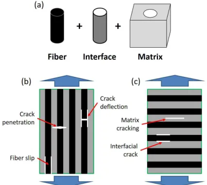
Fig. 1a shows the components of fiber–matrix composite
at the micro-level. Here, the interface is considered an important component that should be carefully characterized [6]-[8]. The to is usually evaluated by a micro-scale testing method such as the single-fiber fragmentation test (SFFT) [9], [10], the push-out test [11], the pull-out test [12], or the micro-bond test [13]. The primary purpose of such evaluations is to elucidate the effectiveness of fiber surface treatments with respect to increasing to [14]. Researchers have reported substantial improvements of to as a result of various surface treatment techniques, indicating that such improvements might improve the mechanical properties of fiber-matrix composites.
the failure mechanisms of the composites might be different. Under longitudinal loading, fiber is firstly broken followed by interfacial cracking or matrix cracking depending on the strength and fracture toughness of them [19]. In contrast, those cracks might firstly appear under transverse loading, which remains the fibers that do not bear the loading. In both longitudinal and transverse loading conditions, to surely determines the failure mechanisms, which directly affects the mechanical properties of the composites.
Substantial analytical and numerical studies have been conducted to elucidate the micro-level effects of to on the ply-level mechanical properties of fiber-matrix composites; these studies have focused on modeling the relationship between micro-mechanics and macro-mechanics [15]. Such studies can be conducted by analyses involving homogenization techniques [16]-[18]. By using these techniques, researchers can predict the effects of local micro-scale cracks at the interface on the mechanical properties of composites. Although these techniques appear to be promising for explaining the effect of to on the mechanical properties of fiber-matrix composites, the experimental validation of these techniques is still a challenging problem due to the scaling difference of evaluations between to and mechanical properties of the composites. Limited experimental studies on the investigation of the relationship between to and mechanical properties of the composite were previously conducted in which micro and ply levels are simultaneously analyzed. As a consequence, the high to values achieved using the previously reported fiber surface treatments are questionable because such treatments have not been demonstrated to positively affect the mechanical properties of fiber-matrix composites. Indeed, direct verification must be obtained via experiments in which the to and the mechanical properties of fiber-matrix composites are simultaneously evaluated.
Fig. 1 Components of composite structures at the micro level (a) and illustrations of longitudinal loading (b) and transverse loading (c) applied to ply composites
In the present work, the effect of to was investigated experimentally. Two composites containing carbon fibers with different surface treatments were tested. The fiber surfaces were first characterized by scanning electron
microscopy (SEM) and time-of-flight secondary-ion mass spectrometry (TOF-SIMS) [20]. The to and fiber strength (σf) were evaluated using SFFT. The mechanical properties of the ply fiber-matrix composites were then evaluated using tensile tests. The specimens were subjected to longitudinal and transverse loadings. In addition, the effects of to on the mechanical properties are comprehensively discussed.
II. MATERIAL AND METHOD
A. Characterization of the Fiber Surface
Two types of carbon fibers HTA 40 (TOHO Tenax Co. Ltd.) with different surface treatments were prepared. The first type was as-received carbon fibers obtained from the manufacturer which contain adhesive material on their surface. The second type was carbon fibers conditioned by being soaked in acetone for more than 5 hours and then rinsed with water. This treatment was conducted to remove any adhesive material on the carbon fiber surface.
The surface roughness of both carbon fibers was observed by using SEM. The purpose is to clarify alterations of the roughness due to the surface treatment. Further, TOF-SIMS analysis to verify that the adhesive material had been removed after the surface treatment was also conducted. The positive secondary ion mode was selected to investigate the material compound in the as-received and conditioned fiber surfaces. The positive ion has high sensitivity to hydrocarbon molecules that might be attached to the fiber surfaces during sizing process. These molecules aim to form strong bonding between carbon fiber and polymer matrix such as epoxy.
The σf and the to were subsequently evaluated by SFFT. The SFFT specimens contained single carbon fiber surrounded by epoxy (Konishi Chemical Co. Ltd). A shear lag model proposed by Kelly-Tyson was used to evaluate σf and to according to the equations shown in Equations 1 and 2, respectively [21]:
(1)
(2)
where σo is the characteristic stress at which fiber cracks appear, Lo is the measured area, Lc is the critical length, m is the Weibull modulus, and d is the diameter of the fibers. Details of the SFFT procedure are described elsewhere [10].
B. Tensile Testing
Fig. 2 Schematic showing the specimen dimensions
The detailed scenarios for tensile testing are reported in Table 1. An Instron tensile testing machine was used with a maximum load of 10 kN. A tensile speed of 2 mm/min at room temperature was applied to all specimens. The load and the displacement were recorded simultaneously until the specimen was broken. The stress-strain curve for each specimen was then obtained from the load-displacement results. From the curve, mechanical properties of the composite were analyzed.
TABLEI TENSILE TESTING SCENARIOS
Loading type As-received fiber– epoxy composite
Conditioned fiber– epoxy composite
Transverse loading
3 specimens (A1, A2, A3)
3 specimens (B1, B2, B3)
Longitudinal loading
3 specimens (A4, A5, A6)
3 specimens (B4, B5, B6)
III.RESULTS AND DISCUSSION
A. SEM Observation
The SEM micrographs are shown in Fig. 3. Figs. 3a and 3b clearly show that the surfaces of both the as-received fibers and the conditioned fibers have uniform porosities parallel to the fiber direction. These uniform porosities are possibly formed during the manufacturing process of the fibers. Later on, manufacturing the composite, the epoxy can fulfill these porosities that can create mechanical locking between the fibers and the matrix and increase to. Figs. 3c and 3d show SEM micrographs of the cross-sectional area of both the as-received fibers and the conditioned fibers. The surface roughness of both fibers was mostly unchanged, which means that the to due to mechanical locking might be retained even after the fibers’ surface was soaked in acetone.
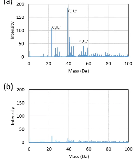
B. TOF-SIMS Analysis
The TOF-SIMS spectra are shown in Fig. 4. The intensity of the hydrocarbon peaks in the 20–60 Da range was substantially lower in the spectrum of the conditioned fiber surface compared with that in the spectrum of the as-received fiber surface. In particular, the peak intensities associated with C2Hn+ in the range from 27 to 30 Da, C3Hn+ in the range from 39 to 44 Da, and C4Hn
+
in the range from 52 to 57 Da drastically decreased [23].
Fig. 3 SEM micrographs of the fiber surface of as-received fibers (a), the conditioned fibers (b), and the cross-sections of the as-received fibers (c) and the conditioned fibers (d)
Fig. 4 TOF-SIMS spectra for the as-received fibers (a) and conditioned fibers (b). The decreased intensity of peaks in the range from 20 to 60 Da indicates that the hydrocarbon at the interface was eliminated
C. SFFT Results
Fig. 5 shows the σf and to values determined from the SFFT results. After the fibers were soaked in acetone, the values of the σf and the to decreased approximately 20% and 50%, respectively. Although the adhesive material was removed from the specimen with conditioned fibers, the low
to still remains. Considering the fibers mainly contain stable carbon compound which is difficult to be reacted with another compound, a plausible explanation of the remaining
to comes from a mechanical locking that prevents shearing-mode crack formation at the interface. The mechanical locking is most likely induced by surface roughness, which remains after the surface treatment, as observed in the SEM images in Fig. 3. Furthermore, by assuming that the stiffness of the fibers (Ef) did not change in response to the surface treatment and assuming that the fiber behavior was linear elastic, we calculated the fiber toughness (Uf) using Equation 3:
(3)
where the value of Ef is 240 GPa, as obtained from the TOHO Tenax Co. Ltd. data sheet. Thus, Uf values of 48 kJ/mm3 for the as-received fibers and 30 kJ/mm3 for the conditioned fibers were obtained using Equation 3. The Uf decreased by approximately 37.5% after the acetone treatment, which indicates that the adhesive material also substantially contributed to the value of Uf.
Fig. 5 Fiber strength (a) and interfacial strength (b) for the as-received and conditioned fibers [10]
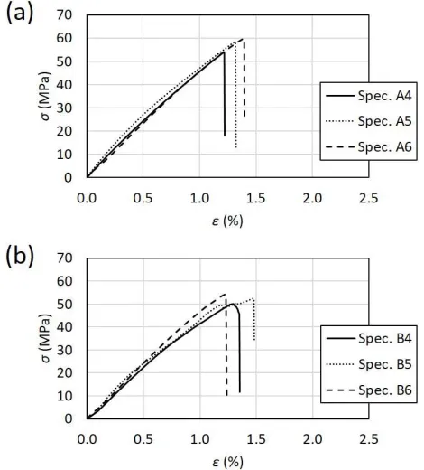
D. Stress-Strain Curves
Stress-strain curves for tensile testing under longitudinal and transverse loadings are shown in Figs. 6 and 7, respectively. The stress-strain curves for three specimens of both the as-received and conditioned fibers show relatively consistent results. In the case of transverse loading testing, nonlinear stress-strain curves that might be caused by the epoxy properties were obtained for both the as-received fibers and the conditioned fibers. These results confirm that nonlinear behavior of the epoxy plays a dominant role in determining the mechanical properties of the composite in the transverse loading direction. Furthermore, the stress-strain curves of the specimens with conditioned fibers decreased to 50%. This result indicates that to strongly affects the mechanical properties of the composite under transverse loading. Considering the composite subjected to transverse loading is always to be the weakest condition, the
to unavoidably determines the overall performance of the composite as load-bearing structures.
Fig. 6 Stress-strain curves of the as-received fiber–epoxy composite (a) and the conditioned fiber–epoxy composite (b) tested under transverse loading
Fig. 7 Stress-strain curves of the as-received fiber–epoxy composite (a) and the conditioned fiber–epoxy composite (b) tested under longitudinal loading
conditioned fibers. These results are related to the linear behavior of the fibers, which dominantly affect the curves. Under longitudinal loading, the to did not substantially decrease the mechanical properties of the composite. Notably, however, the elastic modulus of the composite also slightly changed, which might be caused by ineffective stress transfer between the matrix and the fibers [3].
E. Alteration of Mechanical Properties
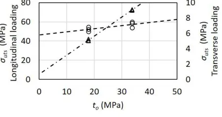
The mechanical properties, i.e., the ultimate tensile strength (σuts) and toughness (U), of the composites under longitudinal and transverse loadings were calculated on the basis of the stress-strain curves obtained via tensile tests. ᴏuts refers to the maximum stress that appears in the curves, whereas U is defined as a total area under the curves. The calculated values of σuts and U are then plotted in Figs. 8 and 9, respectively.
Fig. 8 clearly shows that the σuts under longitudinal loading was only slightly changed. This result is explained on the basis of the mechanism of composite failure under longitudinal loading, where fiber breakage might first occur. Before fiber breakage, the interface does not usually bear relatively high stress; thus, fractures at the interface are avoided. In fact, whether a decrease in σuts is caused by a low
to or by a low σf is uncertain because, under the longitudinal loading condition, fracture occurs via the shearing mode, which can cause mechanical locking that generates additional to. The effect of mechanical locking becomes more dominant for rough fiber surfaces. By contrast, σuts under transverse loading drastically decreases as a consequence of a low to because the interface bears high stress to transfer the load from the matrix to the fiber. At this stage, to plays a very important role and can directly determine σuts. The opening mode of fracture at the interface might also contribute to a decrease in σuts, where the mechanical locking does not effectively prevent fracture of the interface.
As shown in Fig. 9, U exhibits tendencies similar to those observed for σuts. The U drastically decreases under transverse loading because the loading cannot be transferred from the matrix to the fibers as a consequence of a weak interface. Thus, the fibers cannot be deformed to absorb the strain energy from external loading. However, U only slightly decreases under longitudinal loading because the fibers are deformed and broken, resulting in the strain energy from the external loading being absorbed. This result is interesting because low to might not substantially cause low
U.
Under the scenario of composite failure, after cracks form in the fibers, a low to can cause the cracks to first deflect at the interface before penetrating into the matrix. However, a high to causes the cracks to directly penetrate into the matrix. Consequently, the surface area of the cracks generated as a result of a low to is much larger than that of the cracks generated as a result of a high to, which means the absorbed energy required to create the cracks is substantially greater in the case of a low to. The slight decrease of U might only be caused by the decrease of Uf in response to the surface treatment rather than by a low to.
We also note that according to Fig. 9, the values of U are much higher when the composite is subjected to transverse
loading rather than longitudinal loading. This result arises from the ductile properties of the matrix, which enables the absorption of strain energy via matrix deformation. Under longitudinal loading, the fiber cracks cause stress concentration in each point of the composite, which in turn causes the composite to break under the low strain. Thus, the total strain energy absorbed by the composite is relatively low.
Fig. 8 Tensile strength of the composite versus interfacial strength
Fig. 9 Toughness of the composite versus interfacial strength
On the basis of these experimental results, to is demonstrated to strongly affect the mechanical properties of carbon fiber–epoxy composite, i.e., its σuts and U, particularly under transverse loading. Low to can drastically decrease the σuts and U. In contrast, the role of to under longitudinal loading is still questionable. Depending on the failure mechanisms, low to might give benefit to the mechanical properties of the composite because the deflection of fiber crack to the interface prior matrix cracking can increase the strain energy absorption, which delays final failure of the composite. However, when the interfacial cracks appear prior fiber breaks, which is possible for the extremely small to, slip failure mechanism at the interface might occur that causes the mechanical properties of the composite drastically decrease.
general, controlling to values in the manufacturing process of the composite is important to meet requirements of the design structures.
IV.CONCLUSIONS
The effect of interfacial strength on the mechanical properties of a fiber–matrix composite was revealed. The interfacial strength strongly affected the composite under applied transverse loading: the ultimate tensile strength and toughness of the composite decreased by 50% when the interfacial strength was decreased 50%. This relationship might be a consequence of the failed transfer of the load from the matrix to the fibers, rendering the fibers unable to effectively participate in bearing the load and resulting in the appearance of cracks at the interface under low loading. By contrast, the mechanical properties of composites under longitudinal loading only slightly changed in response to changes in interfacial strength because the failure scenario of the composite under longitudinal loading allows fibers to break before cracks occur at the interface or in the matrix. The diminished mechanical properties of the composite are mostly caused by poor mechanical properties of fibers owing to the surface treatment. The role of interfacial strength in determining the mechanical properties of the composite was confirmed in this study.
ACKNOWLEDGMENT
We would like to thank the Center of Advanced Material Analysis Tokyo Institute of Technology for facilitating SEM and TOF-SIMS analyses.
REFERENCES
[1] S. Ben, J. Zhao, Y. Zhang, Y. Qin, and T. Rabczuk, “The interface strength and debonding for composite structures: Review and recent developments,” Composite Structures, vol. 129, pp. 8-26, 2015. [2] G. Simeolia, D. Aciernoa, C. Meolab, L. Sorrentino, S. Iannace, and
P. Russoc, “The role of interface strength on the low velocity impact behaviour of PP/glass fibre laminates,” Composites Part B: Engineering, vol. 62, pp. 88–96, 2014.
[3] B.A. Budiman, F. Triawan, F. Adziman, and I.P. Nurprasetio, “Modelling of Stress Transfer Behavior in Fiber-Matrix Composite 1 under Longitudinal and Transverse Loadings,” Composite interfaces, vol. 24, pp. 677-690, 2017.
[4] N. Ichinose, M. Ishikawa, and K. Morimoto, “Effect of stress transfer between fiber and matrix on toughness of polymer composite,” Polymer Composite, vol. 32, pp. 1617-1624, 2011.
[5] M. Shioya, S. Yasui, and A. Takaku, “Relation between interfacial shear strength and tensile strength of carbon fiber/resin composite strands,” Composite interfaces, vol. 6, pp. 305-323, 1998.
[6] Z. Serge and M. Edith, “Characterization of fiber/matrix interface strength: applicability of different tests, approaches and parameters,” Composite science and technology, vol. 65, pp. 149-160, 2005.
[7] B. Haspel, C. Hoffmann, P. Elsner, and K.A. Weidenmann, “Characterization of the interfacial shear strength of glass-fiber reinforced polymers made from novel RTM processes,” International Journal of Plastic Technology, vol. 19, pp. 333-346, 2015.
[8] B. A. Budiman, K. Takahashi, K. Inaba, and K. Kishimoto. “A new method of evaluating interfacial properties of a fiber/matrix composite,” Journal of Composite Materials, vol. 49, pp. 465-75, 2015.
[9] J.M. Rich and L.T. Drzal, “Round robin assessment of the single fiber fragmentation test,” In: Proceedings of the American society for composites 17th technical conference. Indiana, 21-23 October 2002. p. 1-10.
[10] B.A. Budiman, D. Suharto, K. Kishimoto, F. Triawan, K. Takahashi, and K. Inaba, “Single Fiber Fragmentation Test for Evaluating Fiber-Matrix Interfacial Strength: Testing Procedure and Its Improvements,” In: Proceedings of 15th Seminar Nasional Tahunan Teknik Mesin. Bandung, 5-6 October 2016. p. 809-816.
[11] N. Chandra and H. Ghonem. “Interfacial mechanics of push-out tests: theory and experiments,” Composites Part A: Applied Science and Manufacturing vol. 32, pp. 575-584, 2001.
[12] C.Y. Yue, H.C. Looi, and M.Y. Quek. “Assessment of fibre-matrix adhesion and interfacial properties using the pull-out test Author links open the overlay panel,” International Journal of Adhesion and Adhesives, vol. 15, pp. 73-80, 1995.
[13] M. Nishikawa, T. Okabe, K. Hemmia, and N. Takeda, “Micromechanical modeling of the microbond test to quantify the interfacial properties of fiber-reinforced composites,” International Journal of Solids and Structures, vol. 45, pp. 4098-4113, 2008. [14] J.K. Kocsis, H. Mahmood, and A. Pegoretti, “Recent advances in
fiber/matrix interphase engineering for polymer composites,” Progress in Materials Science, vol. 73, pp. 1-43, 2015.
[15] G. Han, Z. Guan, Z. Li, M. Zhang, T. Bian, and S. Du. “Multi-scale modeling and damage analysis of composite with thermal residual stress,” Applied Composite Materials, vol. 22, pp. 289–305, 2015. [16] F. Greco and G. Sgambitterra, “Validation of Homogenization
Techniques for Locally Periodic Fiber-Reinforced Composites with Interfacial Debonding,” Mechanics of Advanced Materials and Structures 2013, 20(8), 638-651.
[17] R. Azizi, C.F. Niordson, and B.N. Legarth, “On the Homogenization of Metal Matrix Composites using Strain Gradient Plasticity,” Acta Mechanica Sinica, vol. 30, pp. 175-190, 2014.
[18] F. Lebona, S. Dumonta, R. Rizzonic, J.C. López-Realpozod, R. Guinovart-Díazd, R. Rodríguez-Ramosd, J. Bravo-Castillerod, F.J. Sabinae, “Soft and hard anisotropic interface in composite materials,” Composites Part B: Engineering vol. 90, pp. 58–68, 2016. [19] B.K. Ahna, W.A. Curtina, T.A. Parthasarathy, and R.E. Dutton, “Criteria for crack deflection/penetration criteria for fiber-reinforced ceramic matrix composites,” Composites Science and Technology, vol. 58, pp. 1775–1784, 1998.
[20] T. Stephan, “TOF-SIMS in Cosmochemistry,” Planetary and Space Science, vol. 49, pp. 859-906, 2001.
[21] A. Kelly and W.R. Tyson, “Tensile Properties of Fibre-Reinforced Metals: Copper/Tungsten and Copper/Molybdenum,” Journal of the Mechanics and Physics of Solids, vol. 13, pp. 329-350, 1965. [22] M. Elkington, D. Bloom, C. Ward, A. Chatzimichall, and K. Potter.
“Hand-layup: understanding the manual process,” Advanced Manufacturing: Polymer & Composites Science vol. 1, pp. 138-151, 2015.