Vol.7 (2017) No. 5
ISSN: 2088-5334
An Effective Method of Regenerative Braking for Electric Vehicles
Rini Nur Hasanah
#, Victor Andrean
#, Hadi Suyono
#, Soeprapto
##
Electrical Engineering Department, Brawijaya University, Malang 65145 Indonesia
E-mail: [email protected]*, [email protected], [email protected], [email protected]
Abstract— Batteries are commonly used as the power source of plug-in electric vehicles. Low efficiency in a battery is responsible for the low-mileage of electric vehicles. Improving battery efficiency can be done by harvesting the energy wasted during braking, which is commonly called as regenerative braking. The braking energy is to be used to recharge the battery. However, this braking method is not implementable in some conditions, including the conditions when the battery is full, when the vehicle speed is very slow, and when the desired braking currents exceed the converter capability. Therefore, mechanical braking is also still required. This paper proposes a simple but effective technique to deal with the problems found so far in the regenerative braking implementation. The fuzzy-logic theory is implemented to control the sharing proportion between the use of regenerative and electric brakings using one single brake-lever. To improve the current response of electric braking, the proportional-integral control method is used. Being compared to the widely used braking techniques, the method proposed and explored through simulation in this paper offers double advantages, which is increasing the battery efficiency as well as the driving comfort and practicality. The implementation of the method can extend the battery life because the energy regeneration is adapted to the state-of-charge and charging capability of the battery so that the battery can be maintained not to be overcharged.
Keywords—brushless direct current motor; plug-in electric vehicle; regenerative braking system; six-step method; voltage-source inverter.
I. INTRODUCTION
The shortage of fuel oil, as well as its continuously rising price in the world-markets, draws more attention to the development of electric vehicles (EV) than that of internal combustion engine (ICE) vehicles. Some plausible considerations including their associated higher efficiency, low/free emission, no noise, and more comfort make electric vehicles a promising alternative in the future.
The plug-in type of electric vehicles (PEV) uses a battery as its source of energy. However, it has been widely known that its main drawback lies in the limited capacity and efficiency of the battery, which limits the maximum mileage to achieve. Recent developments of EVs have been focusing on improving battery efficiency and capacity.
In conventional electric vehicles, some mechanical braking systems are still provided to decelerate the vehicles. In such kind of braking method the kinetic energy of EVs is changed into heat and wasted through friction pads. An attempt to increase the battery efficiency can be done by restoring the wasted energy back into the battery during deceleration using regenerative braking, which is not possible to do in the ICEs [1]-[4].
The regenerative braking method has undergone many developments. Some of the latest methods include the
addition of a DC-DC converter [5]-[8], the energy storage system using ultracapacitors [9]-[12], and the electronic gearshifts method [13]-[15]. However, some disadvantages are still found in those proposed methods, for example the increase in production cost because a lot of extra components and converters are required, the reduction in efficiency due to power losses in extra converters, and the need of special motor design and complex control algorithm in the electronic gearshifts.
This paper proposes a design of regenerative braking system using bidirectional voltage-source inverter (VSI). Just by controlling the switching sequence of the VSI based on the signals given by some Hall sensors, the brushless direct-current (BLDC) motor widely used in electric vehicles application can be operated in motoring mode or in regenerative braking mode. However, there are some circumstances where the regenerative braking cannot be applied. These conditions include those when the battery is fully charged, when the vehicle speed is very slow, when the vehicle must maintain its position on the uphill/downhill roads, and when the desired braking currents have exceeded the capacity of the converter. Considering all these conditions, a mechanical braking is still needed.
implemented to automatically control the proportion distribution of regenerative and electric brakings through one single brake-lever. To improve the current response of electric braking, the proportional-integral control method is used.
Being compared to the previously proposed methods, the technique proposed in this paper offers some advantages such as increasing the battery efficiency, as well as the comfort and ease of operation [17]. It brings the possibility to operate on all variations of speed just by using a single brake-lever. It is also less costly due to the low need of extra components, resulting in lower production cost. Moreover, the battery life can also be extended because the energy regeneration process is adapted to the state-of-charge (SoC) of the battery, in order not to overcharge the battery.
II. MATERIAL AND METHOD
A. BLDC Motor
A BLDC motor is actually a three-phase alternating– current (AC) synchronous motor with permanent magnets on its rotor. The magnetic field generated by the stator and that generated by the rotor rotation have the same frequency. A self-controlled mode is applied in a BLDC motor due to the existence of rotor position sensors and inverter to control the stator winding current. The reading result of sensors is fed back to the controller to determine the timing of inverter switching.
The rotor position is detected using field-effect sensor being placed on the stator. In general, three field-effect sensors are required to form six variations of rotor position, so that the related inverter is commonly known as six-step inverter.
BLDC motors are suitable for EVs applications due to their good torque-speed characteristics, wide speed-control range, simple structure, high dynamic response, high efficiency and reliability, long operating lifetime (no wearing-out brushes), noiseless operation, and their high torque-to-size ratio[18].
Torque in a BLDC motor can be expressed as,
(1)
and because , then
(2) Eq. (2) indicates that the torque increase is proportional to the armature current increase, which means that the BLDC motor torque can be controlled through its armature current (3).
(3) B. Bidirectional Voltage-Source Inverter (VSI)
The main equipment in this proposed study is a bidirectional voltage-source inverter. It works in both ways, delivering power from the battery to the motor during the acceleration mode, and reversely from the motor to the battery during the regenerative braking process. Fig. 1 shows the equivalent circuit of a BLDC motor which is driven using a VSI, whereas Table I presents the motor parameters considered in this paper.
Fig.1. BLDC motor equivalent circuit being driven using VSI
In Fig. 1, a battery is used as the main power supply. R and L are the resistance and inductance of the motor armature; ea, eb, and ec are the back-emfs; S1-S6 represent the turning-on switches of the inverter; whereas D1 to D6 are the freewheeling diodes. The dc-link capacitor between the battery and inverter is used as temporary energy storage [17].
TABLEI
SPECIFICATION OF MOTOR UNDER CONSIDERATION
Parameters Specification
Brand name QS Motor Nominal voltage 48 VDC
Nominal power 2 kW Winding connection Y Poles number 56 Slots number 63 Armature inductance (test) 1400 μH/phase Armature resistance (test) 0.05 Ω/phase Maximum linear speed 70 km/h Nominal speed 730 rpm
The inverter operation of this BLDC motor is based on the six-step method. During 360 electrical degrees, there are six types of commutation condition. The six-step mode applies the "120° conduction mode", which means that in one commutation condition there are only 2 switches being active simultaneously. Because all the six commutation states have the same principle, the state I in Table II is the only to discuss for explanation.
In functioning the motor under the acceleration mode, the odd-numbered switches (high-side) are to be operated under the pulse-width modulation (PWM) mode using the sequence as determined based on the Hall sensors combination shown in Table II, whereas the even-numbered switches (low-side) continue to turn-on, as seen in the table.
TABLEII
TIMING OF COMMUTATION UNDER ACCELERATION MODE
State
Sensors combination
(a,b,c)
S1 S3 S5 S4 S6 S2
I 101 1 0 0 0 1 0 II 100 1 0 0 0 0 1 III 110 0 1 0 0 0 1 IV 010 0 1 0 1 0 0 V 011 0 0 1 1 0 0 VI 001 0 0 1 0 1 0
Fig.2. Current flow under acceleration mode (state I)
The regenerative-plugging mode takes the benefit of combining the regenerative braking and plugging to get the deceleration. Being compared to the regenerative mode, this braking mode provides the wider braking-current control-range, as well as better efficiency [18]. The regenerative-plugging mode is realized by operating the switches in PWM mode based on the sequence shown in Table III [18].
TABLEIII
TIMING OF COMMUTATION UNDER REGENERATIVE-PLUGGING MODE
State
Sensors combination
(a,b,c)
S1 S3 S5 S4 S6 S2
I 101 0 1 0 1 0 0 II 100 0 0 1 1 0 0 III 110 0 0 1 0 1 0 IV 010 1 0 0 0 1 0 V 011 1 0 0 0 0 1 VI 001 0 1 0 0 0 1
As can be seen in Fig. 3, when the switches S3 and S4 conduct, the current Ion flows from the battery passing the motor windings from node b to a (being opposite to the direction of current in the acceleration mode). In this condition, Ion charges the inductor. When S3 and S4 are off, the inductor discharges to make the current Ioff flow to the battery through the freewheeling diode D1 and D6, as indicated in Fig. 3.
The armature current is obtained using,
(4)
and,
(5)
so that furthermore,
(6)
(7)
(8)
As Vo=RbIb, by substituting (8) into (6), the expression (9) is obtained.
(9)
Fig.3. Current flow under regenerative-plugging mode (state I)
Furthermore, the armature current can be stated as,
(10)
Finally, the relationship between the effective current Ia and Io can be obtained using √(3∕2) as the coefficient factor relating the effective DC current to AC current.
(11)
The ratio between and can be expressed as follows,
(12)
(13)
(14)
(15)
The energy involved during the plugging process is given in (16), whereas the energy being returned to the battery during the regenerative process is given in (17).
(16)
(17)
By considering,
(18)
the ratio between the energy resulted from the regenerative process to that from the plugging process is given as follows:
(20)
C. Magnetic Brake
An important device in this study is a magnetic brake. It is used as the main actuator of the braking action. Its working principle is similar to that of drum brakes on a car. The main difference lies in the use of hydraulic pressure on the drum brakes, while the magnetic brake is driven by electromagnetic force. A simple configuration of a magnetic brake is shown in Fig. 4.
Fig.4. Configuration of a magnetic brake
When a current flows in the magnetic brake, it produces an electromagnetic force which will push the brake shoes (primary and secondary shoes). The brake shoes create frictional forces to generate deceleration torque. The braking torque can be adjusted by controlling the current given to the magnetic brake.
D. Battery
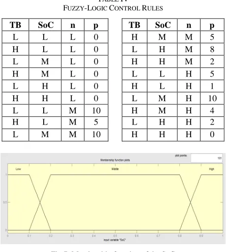
In this study, a battery is used to store energy in the plug-in electric vehicles. The battery considered plug-in this paper was of Lithium type, with the capacity of 20 Ah, the voltage of 12 V, and consisting of 4 batteries in serial connection. The maximum charging current was 15 A. The special characteristics of Lithium battery required that for SoC below 10%, the charging current should not exceed 2 A. The allowed maximum charging current was 15 A when the SoC was within the range of 10%-90%. For the SoC above 90%, the charging current could not exceed 1 A. This design has been adapted based on the characteristics of the battery considered in this paper, otherwise, the fuzzy rule and the associated membership function for the battery should also be different.
E. Braking Method
In order to determine the sharing proportions between the use of the electric braking and the mechanical braking in this regenerative-plugging method, the fuzzy-logic control (FLC) theory is considered [16]. It enables to adjust the speed, the state-of-charge SoC of the battery, and the required braking torque. By using the FLC, the overcharging of the battery and the operation outside its working area are to be avoided. The braking current on the motor armature is controlled using a proportional-integral (PI) controller, as it has been widely known to provide a fast response in real-time error correction [19]. The related actuator used is a magnetic brake. The overall system configuration is shown in Fig. 5.
Fig.5. Block diagram of the control method
It consists of a lever /brake pedal to provide the information about the desired braking torque. The microcontroller unit (MCU) serves to adjust the braking proportion based on the feedback signals (state-of-charge of the battery, the current, Hall sensors), and the input (braking torque command). The MCU output comprises two signals representing two types of duty cycle. The first duty-cycle signal (6 pins) is used to control the bidirectional VSI in order to conduct regenerative-braking process, while the second duty-cycle signal (1 pin) is used to control the magnetic brake.
Fig. 5 also indicates the strategy to control the braking current and the torque sharing between the mechanical and electrical braking modes. There are three entries to the FLC: the braking torque Tbrake provided through the pedal, the state-of-charge (SoC) of the battery, and the vehicle speed. The three inputs are processed to result in the proportion value (p) of the electrical braking. This value is multiplied by the braking torque and the torque constant (Kt = 0.827) to produce the current set-point (Iset), as mathematically represented by (21). Iset represents the desired electric braking current to be present in the armature windings of the motor. The current of the electric braking system is controlled using PI controller with current feedback [19]. The current controller output will result in the electric torque value after being multiplied by the torque constant (Kt), so that the mechanical torque to be applied to the magnetic brake is obtained from the reduction of total braking torque with electric torque, as stated in (22).
(21)
(22)
Regenerative braking torque to be applied to the system depends on many factors so that a single closed-equation is not possible to use. To facilitate the consideration of the sharing proportions between the mechanical and the electrical braking torques, the use of the FLC is beneficial. The FLC rules of the considered braking system with three entries: the braking torque, SoC, and speed, are shown in Table IV [19].
The braking torque Tbrake is divided into two categories, Low and High. The membership function for the braking torque Tbrake is shown in Fig. 6.
that the proportion of the regenerative braking can be increased. When the battery SOC is greater than 90%, the proportion of regenerative braking should be reduced to prevent the overcharging of the battery. The considered membership function is shown in Fig. 7.
Fig.6. Membership function of the braking torque Tbrake
TABLE IV FUZZY-LOGIC CONTROL RULES
TB SoC n p TB SoC n p
L L L 0 H M M 5 H L L 0 L H M 8 L M L 0 H H M 2 H M L 0 L L H 5 L H L 0 H L H 1 H H L 0 L M H 10 L L M 10 H M H 4 H L M 5 L H H 2 L M M 10 H H H 0
Fig.7. Membership function of the SoC
Based on the preliminary simulations previously done, it was found that the regenerative braking was not effective to be applied at speed below 100 rpm so that a purely mechanical braking should be used. For the speed range of 100-400 rpm, the maximum braking current to be achieved was 20 A, while for the speed above 400 rpm it could not exceed 15 A. Considering these conditions, the speed set is divided into three categories, namely: Low, Middle, and High. The related membership function is shown in Fig. 8.
Fig.8. Membership function of the speed
The FLC output is divided into 11 sets, i.e. portion={p0,p1,p2,p3,p4,p5,p6,p7,p8,p9,p10}=(0;0.1;0.2;0.3 ;0.4;0.5;0.6;0.7;0.8;0.9;1). The FLC used in this system adopts the Mamdani method. The membership function of the FLC output is given in Fig. 9.
Fig.9. Membership function of the torque proportion
III.RESULTS AND DISCUSSION
The purpose of the simulation performed during the research was to ensure that the sharing proportion of the braking torques being controlled using the FLC would be applicable to the real systems. The simulation was done to determine the operating area of the VSI under the regenerative-plugging mode. Some rules were obtained as follow:
1) For the speed below 100 rpm, the mechanical braking proportion is 100% to perform deceleration. It is because the regenerative power is smaller than the power losses of the system.
2) For the speed range of 100-400 rpm, the allowed maximum braking current is 20 A.
3) For the speed beyond 400 rpm, the allowed maximum braking current is 15 A.
The results of simulation to obtain the sharing proportions among the torque during the regenerative braking modes, the braking current, and the charging current of the battery, are indicated in Table V. The related graphs are shown in Fig. 10-12.
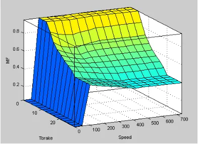
Fig.10. The torque proportion MF as a function of Tbrake and SoC
proportion of regenerative braking will also decrease being adapted to the battery characteristics.
Fig.11. The torque proportion as a function of Tbrake and speed
Fig. 11 displays a three-dimensional representation of the output variable (the regenerative braking torque proportion MF) as a function of the pedal braking torque Tbrake and the speed, as the input variables. For the increasing speed, the proportion of the electric braking will decrease in accordance with the braking-current generated by the converter. For the speed below 100 rpm the sharing of the electric braking is 0%.
Fig.12 The torque proportion as a function of SoC and speed
Fig. 12 illustrates a three-dimensional representation of the output variable (the regenerative braking torque proportion MF) as a function of the state-of-charge SoC of the battery and the vehicle speed, as the input variables. It indicates that while being in the state of Middle SoC, the sharing proportion of the regenerative braking has a high value in order to maximize the battery charging for the vehicle speed above 100 rpm.
The results of laboratory testings done also indicate that the converter could be functioning in its working region and that the battery charging process was in accordance with its characteristics.
IV.CONCLUSION
Some conclusions are drawn based on the analysis of the system being considered in this paper.
The results of simulation show that the proposed method was able to maintain the battery charging characteristics as it should be. When the state-of-charge SoC of the battery was less than 10%, the charging current could not be more than 2
A, when the SoC was in the range between 10% and 90%, the charging current could not exceed 15 A, whereas when the SoC was higher than 90%, the charging current could not be more than 1 A.
The results of experiment indicated that for the speeds below 100 rpm, the electric braking was not favorable anymore because the regenerative power was smaller than the power system losses. Consequently, the proportion of the electric braking should be zero for the speed less than 100 rpm. The simulation results showed that the proportion of the electric braking for the speeds below 100 rpm was 0.05. It was also shown that within the speed range of 100-400 rpm the achieved maximum braking current was not more than 20 A, while beyond the speed of 400 rpm it was not more than 15 A. It means that the desired sharing proportions between the braking modes were achieved.
TABLEV
RESULTS OF EXPERIMENT ON TORQUES DISTRIBUTION USING FUZZY -LOGIC CONTROL
TB SoC (%)
N
(rpm) p Te Tm Ia Io
5.0 10 100 0.05 0.23 4.77 0.28 0.03 5.0 10 101 0.95 4.77 0.24 5.76 0.61 5.0 10 400 0.50 2.50 2.50 3.02 1.26 5.0 50 100 0.05 0.23 4.77 0.28 0.03 5.0 50 101 0.95 4.77 0.24 5.76 0.61 5.0 50 400 0.95 4.77 0.24 5.76 2.40 5.0 90 100 0.05 0.23 4.77 0.28 0.03 5.0 90 101 0.80 4.00 1.00 4.84 0.51 5.0 90 400 0.20 1.00 4.00 1.21 0.50 12.5 10 100 0.05 0.58 11.92 0.71 0.07 12.5 10 101 0.65 8,15 4.35 9.85 1.04 12.5 10 400 0.31 3.88 8.63 4.69 1.95 12.5 50 100 0.05 0.58 11.92 0.71 0.07 12.5 50 101 0.65 8.15 4.35 9.85 1.04 12.5 50 400 0.59 7.34 5.16 8.87 3.70 12.5 90 100 0.05 0.58 11.92 0.71 0.07 12.5 90 101 0.50 6.25 6.25 7.56 0.80 12.5 90 400 0.16 1.95 10.55 2.36 0.98 28.0 10 100 0.05 1.31 26.69 1.58 0.16 28.0 10 101 0.50 14.00 14.00 16.93 1.78 28.0 10 400 0.11 2.97 25.03 3.59 1.50 28.0 50 100 0.05 1.31 26.69 1.58 0.16 28.0 50 101 0.50 14.00 14.00 16.93 1.78 28.0 50 400 0.40 11.20 16.80 13.54 5.64 28.0 90 100 0.05 1.31 26.69 1.58 0.16 28.0 90 101 0.20 5.60 22.40 6.77 0.71 28.0 90 400 0.05 1.31 26.69 1.58 0.66
ACKNOWLEDGMENT
REFERENCES
[1] N. Mutoh, Y. Hayano, H. Yahagi, and K. Takita, “Electric braking controlmethods for electric vehicles with independently driven front and rearwheels,” IEEE Transaction on Industrial Electronics, vol. 54, no. 2, pp. 1168–1176, Apr. 2007.
[2] A. Emadi, Y. J. Lee, and K. Rajashekara, “Power electronics and motordrives in electric, hybrid electric, and plug-in hybrid electric vehicles,” IEEE Transaction on Industrial Electronics, vol. 55, no. 6, pp. 2237–2245, Jun. 2008.
[3] K. T. Chau, C. C. Chan, and C. Liu, “Overview of permanent-magnet brushless drives for electric and hybrid electric vehicles,” IEEE
Transaction on Industrial Electronics, vol. 55, no. 6, pp. 2246–2257,
Jun. 2008.
[4] S. M. Lukic, J. Cao, R. C. Bansal, F. Rodriguez, and A. Emadi, “Energy storage systems for automotive applications,” IEEE
Transaction on Industrial Electronics, vol. 55, no. 6, pp. 2258–2267,
Jun. 2008
[5] K. Takahashi, H. Seki, and S. Tadakuma, “Safety driving control for electric power assisted wheelchair based on regenerative brake.” In
Proc. IEEE International Conference on Industrial Technology,
Mumbai, India: IEEE, 2006, pp. 2492–2497.
[6] J. W. Dixon and M. E. Ortlizar, “Ultracapacitors + DC–DC converters in regenerative braking system,” IEEE Aerosp. Electron.
Syst. Mag., vol. 17, no. 8, pp. 16–21, Aug. 2002.
[7] J. Moreno, M. E. Ortúzar, and J. W. Dixon, “Energy-management system for a hybrid electric vehicle, using ultracapacitors and neural networks,” IEEE Transaction on Industrial Electronics, vol. 53, no. 3, pp. 614–623, Apr. 2006.
[8] M. Marchesoni and C. Vacca, “New DC–DC converter for energy storage system interfacing in fuel cell hybrid electric vehicles,” IEEE
Transaction on Power Electronics, vol. 22, no. 1, pp. 301–308, Jan.
2007.
[9] S. Lu, K. A. Corzine, and M. Ferdowsi, “A new battery/ultracapacitor energy storage system design and its motor drive integration for hybrid electric vehicles,” IEEE Transaction on Vehicular Technology, Vol.56, no. 4, pp. 1516–1523, 2007.
[10] M. Ortúzar, J. Moreno, and J. Dixon, “Ultracapacitor-based auxiliary energy system for an electric vehicle: Implementation and evaluation,” IEEE Transaction on Industrial Electronics, vol. 54, no. 4, pp. 2147–2156, Aug. 2007.
[11] S. M. Kim and S. K. Sul, “Control of rubber tyred gantry crane with energy storage based on supercapacitor bank,” IEEE Transaction on
Power Electronics, vol. 21, no. 5, pp. 1420–1427, Sep. 2006.
[12] J. Wang, B. Taylor, Z. G. Sun, and D. Howe, “Experimental characterization of a supercapacitor-based electrical torque-boost system for downsized ICE vehicles,” IEEE Transaction on Vehicular
Technology, vol. 56, no. 6, pp. 3674–3681, Nov. 2007.
[13] Y.P. Yang and T.J. Wang, “Electronic gears for electric vehicles with wheel motor,” in Proc. 31st Annual Conf. IECON, 2005, pp. 2644– 2648.
[14] Y. P. Yang, J. J. Liu, T. J. Wang, K. C. Kuo, and P. E. Hsu, “An electric gearshift with ultracapacitors for the power train of an electric vehicle with a directly driven wheel motor,” IEEE
Transaction on Vehicular Technology, vol. 56, no. 5, pp. 2421–2431,
Sep. 2007.
[15] Y. P. Yang and T. H. Hu, “A new energy management system of directly driven electric vehicle with electronic gearshift and regenerative braking,” in Proc. Amer. Control Conf., Jul. 2007, pp. 4419–4424.
[16] T. Mohamed, A. Kasa, and M.R. Taha, “Fuzzy logic system for Slope stability prediction,” International Journal on Advanced Science,
Engineering and Information Technology, vol. 2, no. 2, pp. 38-42,
2012.
[17] P. Putera, S.A. Novita, I. Laksmana, M.I. Hamid, and Syafii, “Development and evaluation of solar-powered instrument for hydroponic system in Limapuluh Kota, Indonesia,” International
Journal on Advanced Science, Engineering and Information Technology, vol. 5, no. 5, pp. 284-288, 2015.
[18] M. J. Yang, H. L. Jhou, B. Y. Ma, and K. K. Shyu, “A cost effective method of electric brake with energy regeneration for electric vehicles,” IEEE Transaction on Industrial Electronics, vol. 56, no. 6, pp. 2203-2212, 2009.
[19] B. Dwi Argo, Y. Hendrawan, D.F. Al Riza, A.N. Jaya Laksono, “Optimization of PID controller parameters on flow rate control system using multiple effect evaporator Particle Swarm Optimization,” International Journal on Advanced Science,
Engineering and Information Technology, vol. 5, no. 2, pp. 62-68,
2015.
[20] X. Nian, F. Peng, and H. Zhang,”Regenerative braking system of electric vehicle driven by Brushless DC Motor,” IEEE Transaction