17
Copyright © 2011-15. Vandana Publications. All Rights Reserved.
Volume-5, Issue-3, June-2015
International Journal of Engineering and Management Research
Page Number: 17-23
Experimentation and Analysis of Liquid Cooling System for Electronics
Cooling
P. Chandra Sekhar1, M. Raja Roy2
1,2
Department of Mechanical Engineering, ANITS, INDIA
ABSTRACT
The electronic components have been ruling the world since few decades. Heat dissipation in the electronic components is being a critical issue with the development of chip integrated circuits. Gradual decrease in size of the components has resulted in drastic increase of the amount of heat generation per unit volume. In the present work a copper water block is used as heat sink having overall dimension 38×38×2.5 mm. Pure water is used as cooling fluid. The surface temperature of the aluminum block is tested for 25 W, 54 W and 100 W at different flow rates of water. The temperature of the heated aluminium block is observed at different flow rates of water at each input. It is observed that the convection heat transfer coefficient of water flowing through the copper tubes is increased with increasing the flow rate. The results were analyzed through Response Surface Methodology by Mini Tab software. It is observed that the percentage error is less than 0.5. From Optimization plot it is observed that when the heat input is 25 W minimum surface temperature 30.99760
Keywords— Convection heat transfer coefficient,
Electronics cooling, Heat sink, Heated Aluminium block, Response surface method.
C occurs when the flow rate is 2.7 l/min.
In the present work
Nomenclature
d = inner diameter of copper tube, m Q = heat transfer rate to the water, W Q loss
Q
= loss of heat energy, W
input
m = mass flow rate of water, Kg/s = heat input to the heater, W
Cp
ΔT = Temperature difference, K = Specific heat, Kj/(kg-k)
Ti
T
= inlet Temperature of water, K
o
h
= outlet Temperature of water, K
w = convection heat transfer coefficient, W/m 2
k = thermal conductivity, W/mK
K
Nu = Nusselt number Re = Reynolds number V
EG = Ethylene glycol = velocity of fluid, m/s
l = litres
Subscripts
i = inlet o = outlet w = water
Greek
μ = absolute viscosity of fluid [kg/ms] ρ = fluid density [kg/m3
I.
INTRODUCTION
With the development of microprocessors, heat dissipation problems become more and more serious. They have made its way into practically every aspect of modern life, from toys and appliances to high speed computers. An electronic component depends on the passage of electric current to perform their duties, and they become potential sizes for excessive heating since the current flow through a resistance is accompanied by heat generation.
]
18
Copyright © 2011-15. Vandana Publications. All Rights Reserved.
The failure rate of electronic components increase with increase in temperature. A hot spot created within the electronic components due to low transfer rates seems to be major failure problem. Therefore thermal control has become increasing important in the design and operation of electronic equipment.
As a result of increasing heat loads and heat fluxes conventional cooling technologies such as fan heat sink are unable to absorb and transfer the excess heat. As a result it requires large fans and large heat sinks or new techniques are needed to improve the heat removal capacity. The heat density of the new-generation chips is predicted to exceed 100 W/cm2
Steinke and Kandlikar presented a comprehensive review of conventional single-phase heat transfer enhancement techniques. They discussed several passive and active enhancement techniques for minichannels and micro channels. Some of their proposed enhancement techniques include fluid additives, secondary flows, vibrations, and flow pulsations [3]. The volumetric heat dissipated by computer equipment at each level of the package from the chip to the chassis is having a tremendous impact on the thermal management of computer equipment. Because of the consumer's insatiable desire for increased performance, the competitive pressures are driving the computer manufacturer to pack as much processor/memory performance within the smallest volume possible. The consumer views high performance in a compact package as a benefit. These market pressures seem to be in direct conflict with the desire to continue to provide air cooling solutions for the foreseeable future. Because of these trends in power and package design, other cooling technologies beside air are now becoming viable, techniques, but each must be weighed with many other factors that influence the cooling technology selected. These factors will be discussed along with two specific IBM server packages and their associated cooling technology employed. Finally a microprocessor liquid cooled minichannel heat sink will be described and its performance presented as it applies to a current microprocessor (IBM Power4) chip [4]. Cooling a Microprocessor Chip-Heat spreading, choice of thermal interface materials and proper heat-sink design can
enhance cooling of microprocessor packages and systems
in the near future .As a result, it will be very difficult for the traditional air cooled heat sinks to keep the junction temperature below acceptable values. Another concern is the relatively large size of the air cooled heat sinks which defies the market demand for more compact electronics devices [1]. It will be directed toward micro channels, which invariably involve cooling channels in blocks, as opposed to mini and larger diameter channels that have individual confining walls and are usually thermally well controlled. Using commonly accepted definitions of micro channels, the hydraulic diameter will be in the range 10–200 mm. The length of the flow passages will be on the order of 10 000 micro meter [2].
Saturated critical heat flux (CHF) is an important
experimental conditions. This database has been compared to 6 different correlations and 1 theoretically based model. For predicting the non-aqueous fluids, the theoretical model by Revellin and Thome [Revellin, R., Thome, J.R., 2008. A theoretical model for the prediction of the critical heat flux in heated micro channels. Int. J. Heat Mass Transfer 51, 1216–1225] is the best method. It predicts 86% of the CHF data for non-aqueous fluids within a 30% error band. The data for water are best predicted by the correlation by Zhang et al. [Zhang, W., Hibiki, T., Mishima, K., Mi, Y., 2006. Correlation of critical heat flux for flow boiling of water in mini channels. Int. J. Heat Mass Transfer 49, 1058–1072]. This method predicts 83% of the CHF data for water within a 30% error band. Some suggestions have also been proposed in this paper for the future studies [7].
19
Copyright © 2011-15. Vandana Publications. All Rights Reserved.
increase in surface temperature when diluted ethylene glycol is used as cooling medium when compared to water [9].
II.
EXPERIMENTAL SETUP
The general layout of experimental setup is shown in Fig.1. The major components are heated aluminium block, heat sink made with copper plate and copper tubes, pump, high density cartridge heater and air cooled cross flow heat exchanger. An aluminium block of size 38 × 38 × 70 mm which simulates the heat generated by any electronic equipment is used as the heated block. A hole is precisely machined in the aluminium block to insert the high density cartridge heater of capacity 150 W. Any air gap between the heater and the hole would damage the heater, so heater is fitted in to the hole carefully such that there is no air gap between the two. For heat sink copper tubes are brazed to the copper plate. The numbers of copper tubes are 18.The length of each copper tube is 40 mm having inner diameter 0.36 mm. The overall dimension of copper plate is 38 × 38 × 2.5 mm. The top surface of aluminium block and bottom surface of copper plate are polished to minimise the gaps. Two K type thermocouples are inserted into the surface of the aluminium block at different locations to measure the surface temperature of the heated aluminium block. Another two K type thermocouples are used to measure the outlet temperature of fluid from the heat sink and inlet temperature to the heat sink.
Copper heat sink is placed firmly on the top surface of the aluminium block by using spring force to decrease the thermal resistance. To improve the thermal conductance between the heat sink and heated aluminium block, thermal interface material (TIM) is applied. To minimise the thermal losses to the surroundings glass wool of thickness 40mm is provided all around the heat sink and heated aluminium block assembly. The whole assembly is placed inside a wooden box of size 120×120×150 mm. One more thermocouple is attached to the wooden box to find out the temperature of the insulation provided. The
inlet and outlet diameters of heat sink are 10 mm and 7 mm. A pump having capacity 4 l/min is used to circulate the fluid. A valve is provided between the pump outlet and heat sink inlet to regulate the flow of fluid. An air cooled cross flow heat exchanger is used to decrease the temperature of the hot fluid to room temperature. A dimmer stat is used to supply electric current through the high density cartridge heater at any required voltage. By using voltmeter and ammeter the supplied voltage and current to the heater is measured. A plastic vessel of 5 l capacity is used as a reservoir.
The heat sink and aluminium heated block is shown in Fig .2 and Fig.3 respectively. 18 number of copper tubes were brazed on to the copper plate of overall dimension 38 × 38 × 2.5 mm. The inner and outer diameters of the copper tube are 0.36 mm and 1.0 mm respectively. The length of each copper pipe is 40 mm. The copper tubes were inserted in to two more copper tubes of having inner diameter 5 mm. The fluid enters into one copper tube (larger diameter) and leaves from the other tube after flowing through the copper tubes of smaller diameter.
Fig.2. Copper heat sink
20
Copyright © 2011-15. Vandana Publications. All Rights Reserved.
Fig.3. Heated aluminium block
III.
EXPERIMENTAL PROCEDURE
Initially the setup is tested to ensure that there is no leak in the circuit. For this without giving any heat flux the setup is run with pure water. By using dimmer stat constant heat flux is applied to high density cartridge heater. Flow rate of water is regulated by using a control valve and the flow rate is measured by using a measuring jar. The flow rate is in between 1.1 to 2.7 litres per minute. The surface temperature of the heated aluminium block is taken for different flow rates of water when the heat input is 25 W, 54 W and 100 W. For each flow rate the inlet and outlet temperature of water, surface temperature of aluminium block and surface temperature of wooden box are taken periodically by using digital temperature indicator. The readings are taken till the system reaches steady sate. The Experimental setup is shown in Fig.4. By taking two factors and three levels the results were analyzed through Response Surface Method.
Fig.4. Experimental setup
IV.
CALCULATIONS
Heat loss is calculated from energy balance equation. Reynolds number and convection heat transfer coefficient are calculated from the basic relations as fallows. Heat energy carried away by water is given by
Q = m cPΔT = m cP (To-Ti ) (1)
Heat loss is calculated by using
Q loss = Q Input – Q (2)
Reynolds number is given by
Re = (diVρ)/µ (3)
Convective heat transfer co efficient is calculated from Nusselt number which is the function of Reynolds number and prandtl number.
hw = (Nu× K) /di (4)
To analyze the experimental results through Response Surface methodology two input factors heat and flowrate are chosen as shown in the table 1.
TABLE I
Factor
Levels 1 2 3 Heat 25 54 100 Flow Rate 1.1 1.7 2.7
V.
RESULTS AND DISCUSSIONS
21
Copyright © 2011-15. Vandana Publications. All Rights Reserved.
3031 32 33 34 35 36 37 38 39 40
0 1 2 3
Su
rf
ac
e
tem
per
at
ur
e (
0C)
Volume flow rate of Water (lt/min)
25W
Fig.5. Effect of volume flow rate of water on surface temperature at 25 W heat input
The surface temperature of the aluminium block at different flow rates of water is shown in Fig.6 when the heat input is 54W. There is a reduction of 4.3oC is obtained at 2.7lt/min when compared to the flow rate of 1.1lt/min.When the heat input is 100W there is a reduction of 6.0oC is obtained at 2.7lt/min when compared to the flow rate of 1.1 lt/min which is shown in the fig.7.
30
31
32
33
34
35
36
37
38
39
40
0
1
2
3
Su
rf
ac
e t
emp
er
at
ur
e
(
0
C)
Fig.6. Effect of volume flow rate of water on surface temperature at 54 W heat input
Fig.7. Effect of volume flow rate of water on surface temperature at 100 W heat input
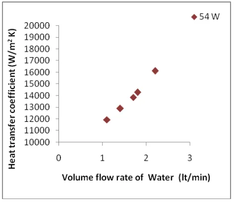
The effect of volume flow rate on convective heat transfer co-efficient of water is shown in Fig.8, 9, and 10 at different flow rates and also at different heat inputs. From the graph we can conclude that the convective heat transfer co-efficient increases with volume flow rate. The convective heat transfer co-efficient increases from 11712 W/m2K to 15814 W/m2K when the volume flow rate changes from 1.1 litres per minute to 2.7 litres per minute at 100W heat input. As the convective heat transfer co-efficient increases heat transfer rate also increases.
22
Copyright © 2011-15. Vandana Publications. All Rights Reserved.
Fig.9.Effect of volume flow rate of water on heat transfer coefficient at 54 W
Fig.10.Effect of volume flow rate of water on heat transfer coefficient at 100 W
From the table II which is obtained through Response Surface Methodology we can observe that the percentage error is less than 0.4per minute and the predicted temperature values are approximately same as that of experimental results.
TABLE II
Heat Flow
Rate Temp Predicted Error %Error
54 1.1 39.7 39.78744 -0.08744 -0.22024
25 1.1 34.5 34.35844 0.141564 0.410331
54 1.7 37.5 37.49469 0.005315 0.014172
25 2.7 31 30.99761 0.002394 0.007722
100 1.7 45.3 45.16136 0.138643 0.306056
54 2.7 35.5 35.41788 0.082122 0.23133
25 1.7 32.3 32.44396 -0.14396 -0.44569
100 2.7 42 42.08452 -0.08452 -0.20123
100 1.1 48 48.05413 -0.05413 -0.11277
The Histogram which gives Frequency verses Residual is shown in Fig.11. Residual verses Fitted value is shown in Fig.12.
0.15 0.10 0.05 0.00 -0.05 -0.10 -0.15 2.0
1.5
1.0
0.5
0.0
Residual
Fr
eq
ue
nc
y
Histogram
(response is Temp)
Fig.11
50 45
40 35
30 0.15
0.10
0.05
0.00
-0.05
-0.10
-0.15
Fitted Value
Re
si
du
al
Versus Fits
(response is Temp)
Fig.12
0.3 0.2 0.1 0.0 -0.1 -0.2 -0.3 99
95 90
80 70 60 50 40 30 20
10 5
1
Residual
Pe
rc
en
t
Normal Probability Plot
(response is Temp)
23
Copyright © 2011-15. Vandana Publications. All Rights Reserved.
100 80 60 40 20 46 44 42 40 38 36 34 32 2.5 2.0 1.5 1.0 Heat M ea n of T em p FlowRateMain Effects Plot for Temp
Fitted Means
All displayed terms are in the model.
Fig.14
The Normal probability plot is shown in Fig.13. The Main effects plot for Temperature is shown in Fig.14. The Interaction plot for temperature and Optimization plot are shown in Fig.15, Fig. 16 respectively.
2.5 2.0 1.5 1.0 50 45 40 35 30 100 80 60 40 20 50 45 40 35 30 FlowRate FlowRate * Heat
Heat * FlowRate
Heat 25 62.5 100 Heat 1.1 1.9 2.7 FlowRate M ea n of T em p
Interaction Plot for Temp
Fitted Means
All displayed terms are in the model.
Fig.15 Cur High Low D: 1.000 Optimal Predict
d = 1.0000 Minimum Temp
y = 30.9976
1.10 2.70
25.0
100.0Heat FlowRate
[25.0] [2.70]
Fig.16
VI.
CONCLUSION
The effect of volume flow rate on surface temperature of the aluminium block which simulates any
electronic device is studied with pure. The effect of the volume flow rate on convective heat transfer is studied. The experimental results are analysed through Response Surface Methodology. It is observed that the percentage error is less than 0.4. When the flow rate changes from1.1 to 2.7 lt/min, 10.1%, 10.5% and 12.5% of reduction in surface temperature is observed for 25w, 54w and 100w heat input respectively.When the flow rate changes from 1.1 to 2.7 lt/min, 25.8%, 25.9% and 26% increase in heat transfer coefficient is observed for 25w, 54w and 100w heat input respectively.
REFERENCES
[1] M. E. Steinke and S. G. Kandlikar, “Single-phase heat transfer enhancement techniques in micro channel and minichannel flows,” in Proc. 2nd Int. Conf. Micro channels Minichannels, Rochester, NY, Jun. 17–19, 2004, pp. 141–148.
[2] Heat Transfer Engineering, Volume 25, Issue 3 April 2004 , pages 3 – 12
[3] Heat Transfer International Research Institute of Universite Libre de Bruxelles and Institute of Thermo physics of Russian Academy of Sciences, Av. Roosevelt 50, B-1050 Brussels, Belgium Accepted 24 May 2006. Available online 27 September 2006.
[4] Université de Lyon, CNRS INSA-Lyon, CETHIL, UMR5008, F-69621, Villeurbanne, France; Université Lyon 1, F-69622, Villeurbanne, France
[5] Electromoatic micro channel cooling system for microprocessor by Kenneth Heat Transfer Engineering, Volume 25, Issue 3 April 2004 , pages 3 – 12
[6] Heat Transfer International Research Institute of Universite Libre de Bruxelles and Institute of Thermo physics of Russian Academy of Sciences, Av. Roosevelt 50, B-1050 Brussels, Belgium Accepted 24 May 2006. Available online 27 September 2006.
[7] Goodson, juan suntiago,Thomas Kenny , linan jinag [8] P. Selvakumar, S. Suresh, Convective performance of CuO/water nanofluid in an electronic heat sink, Exp.Therm.Fluid.Sci.(2012),doi:10.1016/j.expthermflusci. 2012.01.033