Volume 2, Issue 6, June 2013
Page 397
ABSTRACT
Image compression is the application of Data compression on digital images. Data compression is the technique to reduce the redundancies in data representation in order to decrease data storage requirements and hence communication costs. Reducing the storage requirement is equivalent to increasing the capacity of the storage medium and hence communication bandwidth. Thus the development of efficient compression techniques will continue to be a design challenge for future communication systems and advanced multimedia applications. The objective of this paper is to evaluate a set of wavelets for image compression. Image compression using wavelet transforms results in an improved compression ratio. Here in this paper we examined and compared various wavelet families such as Haar, Symlets and Biorthogonal using Discrete Wavelet Transform and Fast wavelet transform. In DWT wavelets are discretely sampled. The Discrete Wavelet Transform analyzes the signal at different frequency bands with different resolutions by decomposing the signal into an approximation and detail information. The study compares DWT and FWT approach in terms of PSNR, Compression Ratios and elapsed time for different Images. Complete analysis is performed at second and third level of decomposition using Haar Wavelet, Symlets wavelet and Biorthogonal wavelet.
KEYWORDS: Discrete Wavelet Transform, Fast Wavelet Transform, Approximation and Detail Coefficients, Border Distortion, Haar, Symlets
1.
INTRODUCTION
The discrete wavelet transform (DWT) refers to wavelet transforms for which the wavelets are discretely sampled. A transform which localizes a function both in space and scaling and has some desirable properties compared to the Fourier transform. The transform is based on a wavelet matrix, which can be computed more quickly than the analogous Fourier matrix. Most notably, the discrete wavelet transform is used for signal coding, where the properties of the transform are exploited to represent a discrete signal in a more redundant form, often as a preconditioning for data compression.
The discrete wavelet transform (DWT) is a mathematical tool that has aroused great interest in the field of image processing due to its nice features. Some of these characteristics are:
1) it allows image multi resolution representation in a natural way because more wavelet subbands are used to progressively enlarge the low frequency subbands;
2) it supports wavelet coefficients analysis in both space and frequency domains, thus the interpretation of the coefficients is not constrained to its frequency behavior and we can perform better analysis for image vision and segmentation; and
3) for natural images, the DWT achieves high compactness of energy in the lower frequency subbands, which is extremely useful in applications such as image compression. The objective of image compression is to reduce redundancy of the image data in order to be able to store or transmit data in an efficient form. Image compression can be lossy or lossless. [1] Lossless compression is sometimes preferred for artificial images such as technical drawings, icons or comics. This is because lossy compression methods, especially when used at low bit rates, introduce compression artifacts. [2] Lossless compression methods may also be preferred for high value content, such as medical imagery or image scans made for archival purposes. Lossy methods are especially suitable for natural images such as photos in applications where minor loss of fidelity is acceptable to achieve a substantial reduction in bit rate. The JPEG 2000 standard [1] proposes a wavelet transform stage since it offers better rate/distortion (R/D) performance than the traditional discrete cosine transform (DCT). Unfortunately, despite the benefits that the wavelet transform entails, some
Image Compression using Fast wavelet
transform viewed from higher compression
ratio and less computation time for different
wavelets
Sandeep Kaur1, Gaganpreet Kaur2, Dr.Dheerendra Singh3
1
Student Masters Of Technology, Sri Guru Granth Sahib World University, Fatehgarh Sahib
2
Assistant Professor, Sri Guru Granth Sahib World University, Fatehgarh Sahib
3
Volume 2, Issue 6, June 2013
Page 398
other problems are introduced. Wavelet-based image processing systems are typically implemented by memory-intensive algorithms with higher execution time than other transforms. In the usual DWT implementation [2], the image decomposition is computed by means of a convolution filtering process and so its complexity rises as the filter length increases. Other fast wavelet transform algorithms have been proposed in order to reduce both memory requirements and complexity, like line-based [5] and block-based [6] wavelet transforms approaches that performs wavelet transformation at image line or block level.1.1 PROBLEM FORMULATION
To perform image compression using Fast Wavelet Transform technique using Mallat Algorithm to overcome the problems of border distortions and large processing times that occur in DWT technique. , when a convolution is performed on finite-length signals, border distortions arise. Use of Symlets, Biorthogonal and Haar wavelets for DWT and FWT implementation on image compression to measure the picture quality subjectively using PSNR and objectively using Compression Ratio. This compression is done in accordance to three wavelet families, Haar, Symlets and Biorthogonal wavelet and results of image compression, PSNR and Compression ratio is to be compared at different levels of decomposition using different images.
2.
DISCRETE WAVELET TRANSFORM
Wavelet transform (WT) represents an image as a sum of wavelet functions (wavelets) with different locations and scales [17]. Any decomposition of an image into wavelets involves a pair of waveforms: one to represent the high frequencies corresponding to the detailed parts of an image (wavelet function ψ) and one for the low frequencies or
smooth parts of an image (scaling function Ø). DWT is a multi resolution decomposition scheme for input signals. The original signals are firs decomposed into two subspaces, low-frequency (low-pass) subband and high-frequency (high-pass) subband. For the classical DWT, the forward decomposition of a signal is implemented by a low-pass digital filter H and a high-pass digital filter G. Both digital filters are derived using the scaling function Φ(t) and the corresponding wavelets Ψ(t). The system down samples the signal to half of the filtered results in the decomposition process. If the
four-tap and non-recursive FIR filters with length L are considered, the transfer functions of H and G can be represented as follows
H (z) = h0 + h1z−1 + h2z−2 + h3z−3 (1) G (z) = g0 + g1z−1 + g2z−2 + g3z−3 (2)
The discrete wavelet transform has a huge number of applications in Science, Engineering, Mathematics and Computer Science. Wavelet compression is a form of data compression well suited for image compression (sometimes also video compression and audio compression). The goal is to store image data in as little space as possible in a file. A certain loss of quality is accepted (lossy compression).Using a wavelet transform, the wavelet compression methods are better at representing transients, such as percussion sounds in audio, or high-frequency components in two-dimensional images, for example an image of stars on a night sky. This means that the transient elements of a data signal can be represented by a smaller amount of information than would be the case if some other transform, such as the more widespread discrete cosine transform, had been used. First a wavelet transform is applied. This produces as many coefficients as there are pixels in the image (i.e.: there is no compression yet since it is only a transform). These coefficients can then be compressed more easily because the information is statistically concentrated in just a few coefficients. This principle is called transform coding. After that, the coefficients are quantized and the quantized values are entropy encoded and/or run length encoded.
3.
MALLAT ALGORITHM
In 1988, Mallat produced a fast wavelet decomposition and reconstruction algorithm [Mal89]. The Mallat algorithm for discrete wavelet transform (DWT) is, in fact, a classical scheme in the signal processing community, known as a two-channel subband coder using conjugate quadrature filters or quadrature mirror filters (QMFs).
The decomposition algorithm starts with signal s, next calculates the coordinates of A1 and D1, and then those
of A2 andD2, and so on.
The reconstruction algorithm called the inverse discrete wavelet transform (IDWT) starts from the coordinates of AJand DJ, next calculates the coordinates of AJ–1, and then using the coordinates of AJ–1 and DJ–1 calculates those
of AJ–2, and so on.
Volume 2, Issue 6, June 2013
Page 399
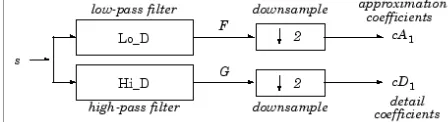
Figure 1: Pyramidal representation of Mallat’s wavelet decomposition algorithm.Given a signal s of length N, the DWT consists of log2N stages at most. Starting from s, the first step produces two sets
of coefficients: approximation coefficients cA1, and detail coefficients cD1. These vectors are obtained by
convolving s with the low-pass filter Lo_D for approximation, and with the high-pass filter Hi_D for detail, followed by dyadic decimation.
The length of each filter is equal to 2n. If N = length (s), the signals F and G are of length N + 2n – 1, and then the coefficients cA1 and cD1 are of length
The next step splits the approximation coefficients cA1 in two parts using the same scheme, replacing s by cA1 and
producing cA2 and cD2, and so on.
4.
MULTILEVEL DECOMPOSITION
The decomposition process can be iterated, with successive approximations being decomposed in turn, so that one signal is broken down into many lower resolution components. This is called the wavelet decomposition tree.
Figure 2: Multilevel Decomposition Lifting schema of DWT has been recognized as a faster approach
The basic principle is to factorize the polyphase matrix of a wavelet filter into a sequence of alternating upper and lower triangular matrices and a diagonal matrix.
This leads to the wavelet implementation by means of banded-matrix multiplications
Volume 2, Issue 6, June 2013
Page 400
Figure 3: Wavelet Decomposition of Image4.1 WAVELET RECONSTRUCTION
The filtering part of the reconstruction process also bears some discussion, because it is the choice of filters that is crucial in achieving perfect reconstruction of the original signal. The down sampling of the signal components performed during the decomposition phase introduces a distortion called aliasing. It turns out that by carefully choosing filters for the decomposition and reconstruction phases that are closely related (but not identical), we can "cancel out" the effects of aliasing.
Figure 4: Wavelet Reconstruction
5.
WAVELET FAMILIES
A wavelet is a wave-like oscillation with an amplitude that begins at zero, increases, and then decreases back to zero. This is also known as one complete cycle it not only has an oscillating wavelike characteristic but also has the ability to allow simultaneous time and frequency analysis with a flexible mathematical foundation. Fourier analysis consists of breaking up a signal into sine waves of various frequencies. Similarly, wavelet analysis is the breaking up of a signal into shifted and scaled versions of the original (or mother) wavelet. Just looking at pictures of wavelets and sine waves, we can see intuitively that signals with sharp changes might be better analyzed with an irregular wavelet than with a smooth sinusoid, just as some foods are better handled with a fork than a spoon.[7] Several families of wavelets that have proven to be especially useful are included in the wavelet toolbox. This paper has used Haar, Symlets and Biorthogonal wavelets for image compression. The details of the Haar, Symlets and Biorthogonal Wavelet are shown below:
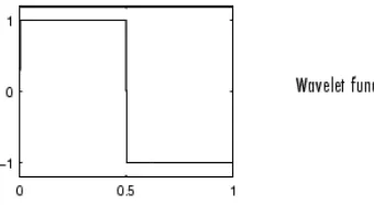
5.1 HAAR WAVELETS
Haar wavelet is the first and simplest. Haar wavelet is discontinuous, and resembles a step function. It represents the same wavelet as Daubechies db1.
Figure 5.1: Haar Wavelet Function Waveform
5.2 SYMLET WAVELETS
Volume 2, Issue 6, June 2013
Page 401
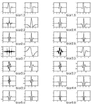
Figure 5.2: Symlet wavelets family5.3 BIORTHOGONAL WAVELETS
This family of wavelets exhibits the property of linear phase, which is needed for signal and image reconstruction. By using two wavelets, one for decomposition (on the left side) and the other for reconstruction (on the right side) instead of the same single one, interesting properties are derived. General characteristics:
Compactly supported
• Biorthogonal spline wavelets for which • Symmetry and exact reconstruction are possible • with FIR filters (in orthogonal case it is impossible). • Family Biorthogonal
• Short name bior
• Order Nr,Nd Nr = 1 , Nd = 1, 3, 5
• r for reconstruction Nr = 2 , Nd = 2, 4, 6, 8 • d for decomposition Nr = 3 , Nd = 1, 3, 5, 7, 9
Figure 5.3 Biorthogonal wavelets family
6 PERFORMANCE PARAMETERS
Input image is to be compressed to a certain level using DWT / FWT based lifting and quantization scheme explained above by maintaining a good signal to noise ratio. Quantitative analysis have been presented by measuring the values of attained Peak Signal to Noise Ratio and Compression Ratio at different decomposition levels. The intermediate image decomposition windows from various low pass and high pass filters.
i. PSNR:
Peak Signal to Noise ratio used to be a measure of image quality. The PSNR between two images having 8 bits per pixel or sample in terms of decibels (dBs) is given by:
PSNR = 10 log10
mean square error (MSE) ii.Compression Ratio:
Ratio of the size of compressed image to the input image is often called as compression ratio.
7 SIMULATIONS AND RESULTS
Volume 2, Issue 6, June 2013
Page 402
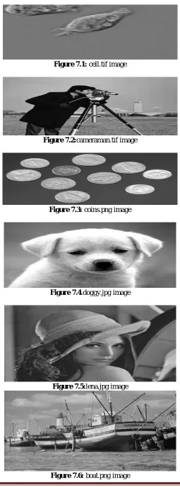
in FWT as compare to DWT in terms of compression ratio, PSNR value and takes less time for compression. Also we see that for all six images FWT takes less time using Haar, sym4 and bior6.8 as compare to DWT using Haar, sym4 and bior6.8.Figure 7.1: cell.tif image
Figure 7.2:cameraman.tif image
Figure 7.3: coins.png image
Figure 7.4.doggy.jpg image
Figure 7.5:lena.jpg image
Volume 2, Issue 6, June 2013
Page 403
QUALITATIVE ANALYSIS1.Using Cell.tif image at 2nd level of decomposition with Haar wavelet
2.Using Cell.tif image at 2nd level of decomposition with sym4 wavelet
3.Using Cell.tif image at 2nd level of decomposition with bior6.8 wavelet
4.Using Cell.tif image at 3rd level of decomposition with Haar wavelet
5.Using Cell.tif image at 3rd level of decomposition with sym4 wavelet
6.Using Cell.tif image at 3rd level of decomposition with bior6.8 wavelet
7.Using Cameraman.tif image at 2nd level of decomposition with Haar wavelet
8.Using Cameraman.tif image at 2nd level of decomposition with sym4 wavelet
Volume 2, Issue 6, June 2013
Page 404
10. Using Cameraman.tif image at 3rd level of decomposition with Haar wavelet11. Using Cameraman.tif image at 3rd level of decomposition with sym4 wavelet
12. Using Cameraman.tif image at 3rd level of decomposition with bior6.8 wavelet
13. Using Coins.png image at 2nd level of decomposition with Haar wavelet
14. Using Coins.png image at 2nd level of decomposition with Sym4 wavelet
15. Using Coins.png image at 2nd level of decomposition with Bior6.8 wavelet
16. Using Coins.png image at 3rd level of decomposition with Haar wavelet
Volume 2, Issue 6, June 2013
Page 405
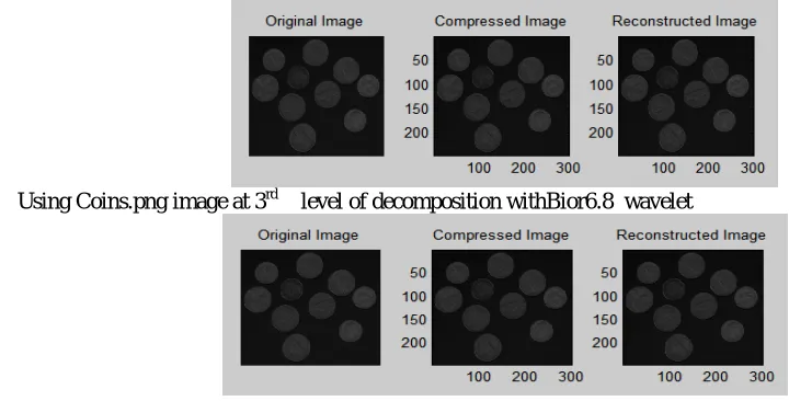
18. Using Coins.png image at 3rd level of decomposition withBior6.8 waveletQUANTITATIVE ANALYSIS
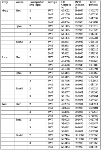
Results obtain by using FWT and DWT in terms of PSNR and Compression Ratios at 2nd and 3rd levels of decompositions. Also, the elapsed time for Haar, sym4 and bior6.8 at 2nd and 3rd level of decomposition have been obtained using different images and shown below in tabular form
Table 1: PSNR values, Compression ratio and Computation Time (in sec) for Haar, Sym4 and bior6.8 Wavelet for cell.tif, cameraman.tif and coins.png image
image wavelet Decompos ition level (input)
technique CR output in % PSNR output in % Elapsed time (sec)
cell Haar 2 FWT 51.0156 99.9942 0.288153
DWT 46.6243 99.9955 0.327576
3 FWT 52.4935 99.9941 0.310751
DWT 48.0469 99.9954 0.395308
Sym4 2 FWT 54.7366 99.9960 0.280954
DWT 54.7366 99.9960 0.356007
3 FWT 55.6949 99.9968 0.385401
DWT 55.6949 99.9968 0.453548
Bior6.8 2 FWT 55.3661 99.9964 0.277785
DWT 55.3661 99.9964 0.327519
3 FWT 55.5569 99.9977 0.345281
DWT 55.5569 99.9977 0.585584
cameraman Haar 2 FWT 48.6893 99.9954 0.322478
DWT 46.7377 99.9959 0.388786
3 FWT 49.7467 99.9954 0.413109
DWT 47.7661 99.9958 0.485752
Sym4 2 FWT 42.7524 99.9976 0.324516
DWT 42.7524 99.9976 0.346042
3 FWT 43.6387 99.9980 0.546554
DWT 43.6387 99.9980 0.562658
Bior6.8 2 FWT 42.2600 99.9979 0.355946
DWT 42.2600 99.9979 0.420431
3 FWT 42.5578 99.9985 0.753409
DWT 42.5578 99.9985 0.846640
coins Haar 2 FWT 50.8600 99.9970 0.325289
DWT 50.2150 99.9972 0.450081
3 FWT 52.6334 99.9969 0.407179
DWT 51.9713 99.9971 0.435345
Sym4 2 FWT 57.8476 99.9963 0.332958
DWT 57.8476 99.9963 0.408551
3 FWT 59.4546 99.9963 0.419544
DWT 59.4546 99.9963 0.465663
Volume 2, Issue 6, June 2013
Page 406
DWT 59.5941 99.9960 0.448396
3 FWT 61.0788 99.9964 0.458306
DWT 61.0788 99.9964 0.470264
Table 2: PSNR values, Compression ratio and Computation Time (in sec) for Haar, sym4 and bior6.8 Wavelet for doggy.jpg image, lena.jpg image and boat.png image
image wavelet Decomposition level (input)
technique CR Output in % PSNR Output in % Elapsed time (sec)
doggy Haar 2 FWT 46.8012 99.9987 0.364275
DWT 46.1576 99.9988 0.457153
3 FWT 47.7030 99.9987 0.443292
DWT 47.0504 99.9988 0.462897
Sym4 2 FWT 53.1415 99.9985 0.389219
DWT 53.1415 99.9985 0.553523
3 FWT 54.1175 99.9986 0.447730
DWT 54.1175 99.9986 0.552284
Bior6.8 2 FWT 55.5801 99.9984 0.425733
DWT 55.5801 99.9984 0.558716
3 FWT 55.8321 99.9986 0.482315
DWT 55.8321 99.9986 0.579133
Lena Haar 2 FWT 47.7650 99.9947 0.327411
DWT 46.4598 99.9952 0.379040
3 FWT 48.4780 99.9948 0.368000
DWT 47.1548 99.9953 0.380791
Sym4 2 FWT 53.4154 99.9956 0.323869
DWT 53.4154 99.9956 0.362464
3 FWT 53.7896 99.9964 0.401916
DWT 53.7896 99.9964 0.444737
Bior6.8 2 FWT 55.8577 99.9961 0.363226
DWT 55.8577 99.9961 0.373260
3 FWT 55.1884 99.9974 0.427854
DWT 55.1884 99.9974 0.438346
boat Haar 2 FWT 45.2053 99.9901 0.640914
DWT 44.9703 99.9903 0.684894
3 FWT 46.2345 99.9898 0.717617
DWT 45.9927 99.9900 0.728460
Sym4 2 FWT 54.0925 99.9876 0.627784
DWT 54.0925 99.9876 0.669877
3 FWT 55.0761 99.9884 0.736906
DWT 55.0761 99.9884 0.804531
Bior6.8 2 FWT 55.7164 99.9880 0.715955
DWT 55.7164 99.9880 0.738092
3 FWT 56.4153 99.9900 0.828260
DWT 56.4153 99.9900 0.840720
8.
CONCLUSION AND FUTURE SCOPE
Volume 2, Issue 6, June 2013
Page 407
compare to DWT. Although picture visual quality or PSNR achieved with fast wavelet transform is slightly similar than that of discrete wavelet transform technique but the compression ratio achieved with fast wavelet transform is more than that of discrete wavelet transform technique.REFRENCE
[1.]Kaleka,Jashanbir Singh., Sharma,Reecha.,“Comparativ performance analysis of Haar,Symlets and Bior wavelets on image compression using Discrete wavelet Transform”, International journal of Computers and Dstrbuted
Systems, Volume 1,Issue 2,August,2012
[2.]M. Antonini, M. Barlaud, P. Mathieu, and I. Daubechies, Image coding using wavelet transform, IEEE Trans. Image Processing, vol. 1, pp.205-220, 1992.
[3.]P.L. Dragotti, G. Poggi, and A.R.P. Ragozini, Compression of multispectral images by three-dimensional SPIHT algorithm, IEEE Trans. on Geoscience and remote sensing, vol. 38, No. 1, Jan 2000.
[4.]Thomas W. Fry, Hyperspectral image compression on recon_gurable platforms, Master Thesis, Electrical Engineering, University of Washington, 2001.
[5.]Kumari,Sarita., Vijay,Ritu., “Analysis of Orthogonal and Biorthogonal Wavelet Filters for Image Compression”,
International Journal of Computer Applications , Volume 21– No.5, May 2011
[6.]A. Islam and W.A. Pearlman, An embedded and efficient low-complexity hierarchical image coder, in Proc. SPIE Visual Comm. and Image Processing, vol. 3653, pp. 294-305, 1999.
[7.]B. Kim and W.A. Pearlman, An embedded wavelet video coder using three-dimensional set partitioning in
hierarchical tree, IEEE Data Compression Conference, pp.251-260, March 1997.
[8.]Kumar,V., V.Sunil., Reddy,M.Indra Sena., “Image Compression Techniques by using Wavelet Transform”, Journal of information engineering and applications, Vol 2, No.5, 2012
[9.]Katharotiya,Anilkumar., Patel,Swati.,“Comparative Analysis between DCT & DWT Techniques of Image Compression”, Journal of information engineering and applications, Vol 1, No.2, 2011
[10.]S. Mallat, Multifrequency channel decompositions of images and wavelet models, IEEE Trans. Acoust., Speech, Signal Processing, vol. 37, pp.2091-2110, Dec. 1989.
[11.]A.N. Netravali and B.G. Haskell, Digital pictures, representation and compression, in Image Processing, Proc. of Data Compression Conference, pp.252-260, 1997.
[12.]E. Ordentlich, M. Weinberger, and G. Seroussi, A low-complexity modeling approach for embedded coding of
wavelet coef_cients, in Proc. IEEE Data Compression Conf., Snowbird, UT, pp. 408-417, Mar. 1998.
[13.]W.A. Pearlman, Performance bounds for subband codes, Chapter 1 in Subband Image Coding, J. W. Woods and Ed. Klvwer. Academic Publishers, 1991.
[14.]Proposal of the arithmetic coder for JPEG2000, ISO/IEC/JTC1/SC29/WG1 N762, Mar. 1998.
[15.]A. Said and W.A. Pearlman, A new, fast and ef_cient image codec based on set partitioning in hierarchical trees, IEEE Trans. on Circuits and Systems for Video Technology 6, pp. 243-250, June 1996.
[16.]P. Schelkens, Multi-dimensional wavelet coding algorithms and implementations, Ph.D dissertation, Department of Electronics and Information Processing, Vrije Universiteit Brussel, Brussels, 2001.
[17.]J.M. Shapiro, Embedded image coding using zerotrees of wavelet coef_cients, IEEE Trans. Signal Processing, vol. 41, pp.3445-3462, Dec. 1993.
[18.]D. Taubman, High performance scalable image compression with EBCOT, IEEE Trans. on Image Processing, vol. 9, pp.1158-1170, July,2000.
[19.]I.H. Witten, R.M. Neal, and J.G. Cleary, Arithmetic coding for data compression, Commun. ACM, vol. 30, pp. 520-540, June 1987.