Volume 2, Issue 10, 2015
31 Available online at www.ijiere.com
International Journal of Innovative and Emerging
Research in Engineering
e-ISSN: 2394 - 3343 p-ISSN: 2394 - 5494
Hybrid Controller-based Active Line Conditioner
Dr.M.C.Tripathy, Dr.D.P.Bagarty and Prof. S.Behera
*
College of Engineering and Technology, Bhubaneswar *e-mail: [email protected]
ABSTRACT:
A single-phase Synchronous Link Converter (SLC) is modeled with a reactive and non-linear load. The technique of Sliding Mode Control (SMC) is used in SLC so as to act as Active Line Conditioner. The main objective of using SLC is to act as Active Power Filter for harmonics compensation and power factor correction of the load. A hybrid controller, which is the combined conventional PI and fuzzy controller, is incorporated in SLC. Initially in order to study the performances of SLC (i.e., merits and limitations), it is operated with PI and Fuzzy controller separately. Later merits of both the controls(i.e., PI and Fuzzy) are taken up and it has been transformed into a hybrid controllers to ALC. The ALC is connected to the point of common coupling and simulated using MATLAB/Simulink. The results from simulations are presented for justifications.
Keywords: Synchronous Link Converter (SLC), Hybrid Controller, Active Line Conditioner (ALC), Sliding Mode Control (SMC), MATLAB/Simulink
I. INTRODUCTION
With rapid growth in semi-conductor based power converters and non-linear loads used by both industrial and domestic units, the deterioration in voltage and current waveforms has raised significantly of the power system. The harmonics generated by nonlinear load when added with reactive load causes more problematic to supply system as it not only affects transformer at supply end, but also to other consumers connected to same supply. Due to these problems, the power quality is an issue and an object of great concern not only for consumers but also for distributors.
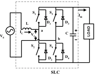
The Synchronous Link Converter (SLC) shown in Fig.1 is so named, as it resembles the phasor diagram of Synchronous machine driving a dc motor with an ac to dc converter rectifying/regenerating the power [1]. On the other hand, the SLC is connected between source and load for the control of bi-directional power-flow. The ac current through SLC shown here is designated as iL, which is same as the source current when SLC is connected between source and load
as shown in Fig. 1. The vector relationships of ac side voltages and current under rectifying and regenerative mode are shown in Fig. 2. For successful operation of SLC, the voltage across the capacitor connected to its dc side is maintained adequately high as compared to peak of its supply voltage so that diodes in the converter are normally maintained in reverse-biased condition [1]. The ac side of inverter voltage is designated as VI and XL is inductive reactance between Vs
and VI. When harmonic or var compensation is needed, the SLC is connected as shunt across the line. Such connection of
SLC is also known as Synchronous Static Compensator (SSC) (i.e., popularly known as Static Compensator/STATCOM). For harmonic compensation, the SLC acts as Active Power Filter (APF)[2-5], whereas for var compensation it is referred as Var Compensator. When either operation (harmonics compensation and var compensation) is needed simultaneously, the operation of SLC is referred as Active Line Conditioner (ALC). Under such case, ac side current SLC (iL) is known
as compensating current which is different from the source current. The vector relationships of ac side voltages and current in case of ideal var compensator (i.e., under inductive and capacitive operation) are shown in Fig. 3.The connection arrangement is shown in proposed circuit diagram in Fig. 4. The use of Sliding Mode controller has been illustrated in [6-7]. The Fuzzy Logic Controller (FLC) which has been used on various applications [ 8-11], has been an added advantage in recent times. This paper presents the use hybrid controller in SLC and a comparison among controllers has been cited to justify its necessity. The whole circuit is simulated with MATLAB/Simulink to realize the physical type situation. The results from simulations are presented and found to be satisfactory.
II. INVERTER MODEL
Volume 2, Issue 10, 2015
32 must be larger than the peak of ac source by which it enables the inductor current to be shaped as required at any point in the line cycle.
During positive half cycle of source voltage (Vs), the current through SLC ‘iL’ can be made more positive by making
vI = 0 and iL can be driven toward zero by making vI = vC. The voltage across the inverter (i.e., between inductor L and
bridge shown in Fig. 1) is designated as ‘vI‘ and it’s capacitor voltage is designated as ‘vC‘. During negative cycle of
input voltage, iL can be made more negative by making vI = 0 and iL can be driven toward zero by making vI = -vC. Above
facts conclude that two legs of an inverter can be used for different tasks. The switches S3 and S4 are used to force actively
shape vI 0 and vI 0 respectively, while switches S1 and S2 are used to actively shape inductor current [5]. Further, it is
to be noted that the switches of each inverter leg must operate in a complementary fashion. That is one switch must be conducting at all times. This gives the switching state
S1 + S2 = 1 (1)
and S3+ S4 = 1 (2)
The voltage across inverter output Vi can be derived based upon switching state as follows. Vi= ( S1 S2 – S3 S4 ) Vc = SS Vc (3)
where SS (switching status) = ( S1 S2 – S3 S4 )
With the above equations (1~3), the state equations for the inductor current and capacitor voltage. If the coil is not pure inductive, then it has small resistive component (R) and inductive component (L). So the state equations are written as follows.
D iL = - (R/L) iL + Vs – SS vC (4)
D vC = (SS/C) vC (5)
where ‘D’ stands for derivative d/dt
III.SLIDING MODE CONTROL AND CONTROLLING MECHANISM
Sliding Mode Control is concerned with forcing one/more variable to follow a specific trajectory which is known as sliding surface [6-7]. The location of variables relative to sliding surface, which governs control law, is applied to the system. The starting point with sliding mode control is the definition of the sliding surface. For our objective, it is necessary to force the source current to be same shape in phase with source voltage. Therefore, the trajectory of line current is defined to be
iS* = kVs (6)
When the line current is on the sliding surface (S), the equation is written in standard form as
S = iS - kVs = 0 (7)
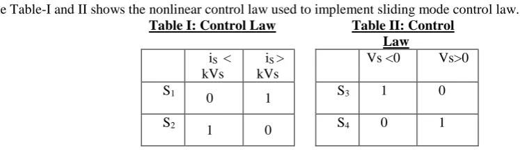
The Table-I and II shows the nonlinear control law used to implement sliding mode control law.
Table I: Control Law Table II: Control
Law iS <
kVs
iS >
kVs
Vs <0 Vs>0
S1 0 1 S3 1 0
S2
1 0 S4 0 1
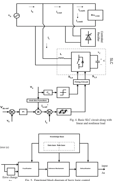
The close-loop controlling mechanism is shown in Fig. 4. By close-loop controlling action, the reference voltage V dc-ref of capacitor is made to be more than peak of ac source voltage. This reference voltage is compared with the actual
capacitor voltage and the voltage error is processed through proportional and integral controller (PI). To follow the sliding mode control, the unit sine function is derived from the voltage source and multiplied with the output of PI control to obtain the reference alternating source current. This current is then compared with actual source current and error is processed through hysteresis controller to generate the gating pulses of switches S1 and S2. The source voltage is scaled
down by a gain constant ‘Cg’ and taken through signum function to generate firing pulses S3 and S4.
IV.FUZZY LOGIC CONTROL
The performance of Fuzzy logic controller is well documented for improvements of both transient and steady state performances. The function of fuzzy logic controller is very useful since exact mathematical model of it is not required.
The fuzzy logic control system (Fig.5) can be divided into four main functional blocks namely Knowledge base,
Fuzzification, Inference mechanism and Defuzzification [8,10-11]. The knowledge base is composed of data-base and
Volume 2, Issue 10, 2015
33 input that finally drives the motor. This control input may be change in torque, flux, or speed component. The typical input membership functions for speed error and change in speed error are shown in Fig. 6 and Fig. 7 respectively, whereas the output membership function for change in control input is shown in Fig. 8. The output generated by fuzzy controller must be crisp which is used to control the drive unit and this is accomplished by the defuzzification block. Knowledge base involves defining the rules represented as a set of if then rules, for example if speed error is positive large ‘PL’ and error
change is negative large ‘NL’, then change in output is zero ‘Z’. The control rules are evaluated by inference mechanism.
Many defuzzification strategies are available [8], such as, the weight-average criterion, the mean-max membership, and center-of-area (centroid) method. The defuzzification technique using centroid method is summarized as follows and shown in Fig. 5. Suppose the voltage error is –20 and change in voltage error is -17, then e will be NS and the change in error will be PS or PL. So the rules relating the error and error rate are shown in Table-III.
If ‘e’ is ‘NS’ and ‘de’ is ‘PS’ then change in control input is ‘Z’ (Fig. 9(a)) .If ‘e’ is ‘NS’ and ‘de’ is ‘PL’ then change in control input is ‘PS’ (Fig. 9(b))
By using the most commonly used defuzzification method, i.e. the Center-of-area method, the defuzzified values of increment in control inputs are obtained as
C* = (C1 * A1 + C2 * A2)/ (A1+A2).
where C1, A1: - Centroid and area derived (i.e., from Fig. 9(a)) from membership function for change in control
input. Similarly, C2 and A2 represent centroid and area shown in Fig. 9(b).
Table-III: Rules for error and change in error
Error(e)
PL PS Z NS NL
Change in
error (de/dt)
NL PL PL PS PS Z
NS PL PL NS Z NL
Z PL PS Z NS NL
PS PS Z NS NL NL
PL Z NS NS NL NL
V. SIMULATION RESULTS
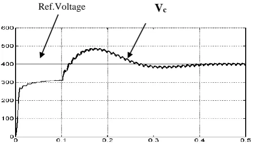
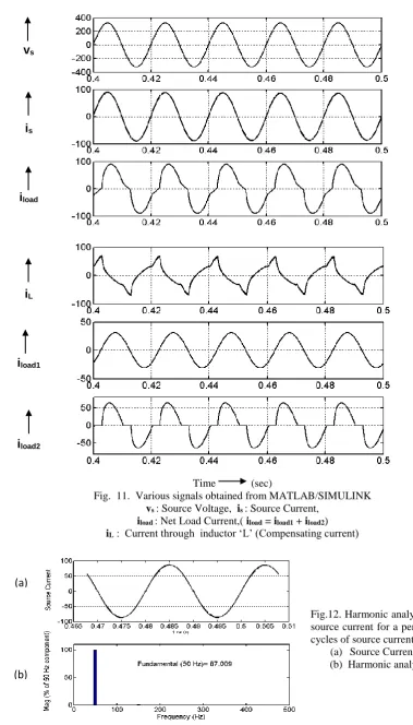
The SLC acting as Active Line Conditioner (ALC) is transformed into various block sets using MATLAB/Simulink. The load is built using two different loads. One is using a linear load (R-L) and another is nonlinear load using a phase-controlled rectifier feeding R-L load. The source voltage of , 230 V rms and 50 Hz is considered here. The passive components of SLC (i.e., ac side inductor and dc capacitor) are considered as 2.1 mH and 10000F respectively. Simulation results are presented in Figs. 10-12. Initially the capacitor is allowed to charge to peak of ac input voltage with open-loop. . The closed-loop control is activated at the time of 0.1 sec. With activation of closed-loop control system, the capacitor voltage is charged to reference dc voltage 400V which is necessary for SLC its satisfactory operation. The response of capacitor voltage with respect to reference voltage is shown in Fig. 10. The net load current iLoad, which is summation of
linear load current (iLoad1) and nonlinear load current (iLoad2) along with source voltage are shown in Fig. 11 during
steady-state. The load current ‘iLoad1’ lags source voltage vs by 450. It also shows the load current iLoad, along with source current
(is) and compensator current (ic). It is observed that the source current follows the pattern of input voltage thus resulting
input power factor close to unity and making the source current independent of harmonics. It also show that the various waveforms during one fundamental cycle. Current through capacitor becomes positive when two diodes across switches conduct and negative capacitor current implies the conduction of any two switches.
During handling PI controller and Fuzzy controller, it is observed that PI gives better transient response than FLC. On the otherhand FLC gives better performance during dynamic response as compared to PI control when the system is subjected to small signal perturbation in load . So merits of both the controllers are considered while using hybrid controller in ALC (i.e., during transient period, PI controller is used. Once transient period is over, PI controller is replaced by FLC). The performance index of both PI and FLC is cited in Table-IV.
Volume 2, Issue 10, 2015
34 VI.CONCLUSION
This paper has focused on a single-phase SLC acting Active Line Conditioner. Program was developed with the help of MATLAB/Simulink so as to establish a physical type situation. The ALC was connected across the point of common coupling and was modeled with hybrid control under SMC so as to shape the non-sinusoid current to sinusoid one effectively thus resulting power factor close to unity and restrict the source harmonics within permissible limit. A comparative study was presented between PI and FLC so as extract their merits and those merits were utilized in ALC under hybrid control. Above all it is concluded that FLC not only provides faster dynamic response while it is subjected to small signal perturbation, but also exhibits less THD as compared to PI controller.
REFERENCES
[1] V.R. Kanetkar, M.S. Dawande and G.K.Dubey, “Recent advances in synchronous link converters,” The IETE Book
Series, TMH Publications, vol. 1, pp. 131-151, yr-1993.
[2] Bhim Singh, A.Chandra, and K. Al-Haddad, “Computer aided modelling and simulation of active power filters,” in
Electrical Machines and Power Systems, 27, pp 1227-1241, yr-1999.
[3] Bhim Singh, K. Al-Haddad, and A.Chandra, “A review of active power filters for power quality improvement,” in
IEEE Trans on Industrial Electronics, vol. 46, no. 5, pp 1-12, yr-1999.
[4] R.M. Duke and S.D. Round, “The steady state performance of a controlled current active filter”, IEEE Trans on Power
Electronics, vol-8, pp 140-146., yr-1993.
[5] D.A. Torrey and Adel M.A.M. Al-Zamel, “Single phase active power filters for mulltiple nonlinear Loads,” in IEEE
Trans on Power Electronics, vol. 10, no. 3, pp. 263-272, May- 1995.
[6] A. Sabanovic, N.Sabanovic, O.Music, “Sliding mode control of dc-ac converter,” in IEEE Trans on Power Electronics
Specialists Conf. Rec., pp. 560-566, yr-1986.
[7] M. Carpita, et al., “Power conditioning system using sliding mode control,” in IEEE Trans on Power Electronics
Specialists Conf. Rec., pp. 626-633, yr-1988.
[8] S.Behera, B.Subudhi, S.P.Das and S.R.Doradla, “Fuzzy controller-based high performance Induction motor drive,”
in IEE Ntional Conference proceeding, PEPEM-2005, TIET Patiala, pp 51-54, yr-2005
[9] B.Panda and S.Behera, “Modelling of Sliding Mode Controller-based synchronous Converter as Active Line conditioner,” in IEEE International Conference, PSACO-2008, AU College of Engg, Visakhapatnam (AU)., yr-2008. [10]S.Behera, N.Sahoo and B.Panda, “Fuzzy-Controller based SATCOM as Active Power Filter,” in Conference
Proceeding of EPTMITA-06, M.M.M. Engg College, Gorakhapur,pp-06, yr-2006.
[11]B.Panda, A.K.Mahapatra, D.P Bagarty and S.Behera, “Fuzzy Controller-based dynamic voltage restorer for mitigation of voltage sag,” in International Journal of Engineering Science and Technology, vol.3, no.2, pp.996-1007, yr-2011.
TABLE-IV: Performance index with FI and FLC
PI Controller FLC
Transient response Less than quarter cycle
Little more than quarter cycle
Dynamic response of load voltage
Nearly One cycle Less than a quarter cycle
Volume 2, Issue 10, 2015
35 Fig. 2. Phasor diagram of SLC under
(a) motoring (b) generating mode
(a)
(b)
v
sv
ii
Lx
Li
Li
Li
Lx
Lv
iv
sFig. 1. Basic Circuit of Synchronous Link Converter
D
1S
1S
3D
3D
2S
2D
4S
4C
a
b
V
SL
L
O
A
D
V
II
dcI
CSLC
i
Lx
Li
Lv
iv
sFIG.3.PHASOR DIAGRAM OF SLC (a) inductive operation (b) capacitive operation
(a)
(b)
v
si
Lx
Li
LVolume 2, Issue 10, 2015
36 Fig. 4. Basic SLC circuit along with
linear and nonlinear load
C
o
n
tro
lle
d
R
e
ct
ifie
r
L
C
S
L
C
vC
PI
Unit Sin Function
Vdc-ref
vC
vS
is-ref*
is vs
Firing Circuit
S1,2 S3,4
Cg
R-LLOAD
iS i
Load
iLoad1
iLoad2
iL
Error (e)
input
u Error change
e
Knowledge Base
Data base Rule base
Fuzzification Inference Mechanisim Defuzzification
Volume 2, Issue 10, 2015
37 Fig. 10 Voltage response of capacitor voltage (Vc)
with respect to reference voltage of 400 when controller is activated during time =0.1 sec
V
c Ref.Voltage(a)
(b)
Fig.9 . Defuzzificztion technique using centeroid method
NS PS Z
-20 17
C1, A1
NS PL PS
-20 17
C2, A2
NL NS PS PL
1 Z
-40 -30 -20 0 20 30 40
u ---
Fig.8. Memberhip function for change in control input
NL NS PS PL
1
Z
0 15 50 90
-15 -50 -90
e ---
Fig.6. Memberhip function for error
NS PS PL
1
Z NL
-20 -15 -5 0 5 15 20
e ---
Volume 2, Issue 10, 2015
38 Fig.12. Harmonic analysis from
source current for a period of 2 cycles of source current
(a) Source Current (b) Harmonic analysis
(a)
(b)
Time (sec)
Fig. 11. Various signals obtained from MATLAB/SIMULINK vs : Source Voltage, is : Source Current,
iload: Net Load Current,( iload = iload1 + iload2)
iL: Current through inductor ‘L’ (Compensating current)