[Sharma* 5(4): April, 2018] ISSN 2349-4506
Impact Factor: 3.799
G
lobal
J
ournal of
E
ngineering
S
cience and
R
esearch
M
anagement
DESIGN OF ROBUST YOULA-KUCERA CONTROLLER FOR SERVO MOTOR
USING MULTI-OBJECTIVE PARTICLE SWARM OPTIMIZATION
Ms. Anshu Sharma*, Dr. Shiv Narayan
*Department of Electrical Engineering, PEC University of Technology, Chandigarh, India Department of Electrical Engineering, PEC University of Technology, Chandigarh, India
DOI: 10.5281/zenodo.1215962
KEYWORDS
:
Youla-Kucera parameterization, robust, disturbance rejection, servo system, multi-objective.ABSTRACT
In this paper a novel Youla-Kucera parameterization based robust controller is designed using multi-objective particle swarm optimization. The design approach is developed for SISO system and is implemented on servo system. The design approach developed achieves multiobjectives related to robustness and disturbance rejection.
INTRODUCTION
In controller design, the Youla-Kucera Parameterization is useful as in it we can represent all the closed loop transfer functions in terms of Youla-Kucera parameter Q. This paper presents a methodology to address the problem of composite measure for multi-objective optimal performance of SISO systems. This technique solves
H∞ and time domain characteristic constraints problems of SISO systems, simultaneously. We get desired optimal
multi-objective performance in the presence of conflicting objectives.
YOULA-KUCERA PARAMETERIZATION OF STABILIZING CONTROLLERS
Consider the plant of order n with
G
0
s
as nominal transfer function and the SISO feedback configuration as shown in the Figure 1[1].Figure 1: Control system consisting of a controller with fixed structure and a plant with model uncertainty
n n
a
b
s
G
0
(1)
Let
a
nandb
n are coprime polynomials andC
ˆ
is the proper stabilizing controller of order m with coprime polynomialsx
ˆ
n andy
ˆ
n in a feedback framework,
n n
x
y
s
C
ˆ
ˆ
ˆ
(2)
[Sharma* 5(4): April, 2018] ISSN 2349-4506
Impact Factor: 3.799
G
lobal
J
ournal of
E
ngineering
S
cience and
R
esearch
M
anagement
bQ x aQ y x y s C ˆ ˆ (3) where, d n d n d n d n d nq
q
Q
x
y
y
x
x
x
a
b
b
a
a
a
,
,
ˆ
ˆ
,
ˆ
ˆ
,
ˆ
(4)d
a
andx
d are two polynomials which form a polynomial 𝑎𝑑𝑥𝑑 so that dega
d
n
anddeg
x
d
m
. Q is an arbitrary proper stable rational parameter, so that polynomialq
ˆ
d is stable and polynomialn
q
ˆ
has same or lower degree [5].Polynomial YK parameters can be recovered from the controller polynomials via the following relation:
n n n n n n d ny
x
b
a
x
y
q
q
ˆ
ˆ
(5)
YK parameters are polynomials.
OPTIMIZING CONTROLLER STRUCTURE WITH MULTI-OBJECTIVE OPTIMIZATION TECHNIQUE
Youla-Kucera can be used as structure of the controller which is then optimized with the multi-objective optimization technique. There is a trade-off between the controller order and the performance of the closed loop system. This multi-objective optimization problem gives a family of non-dominated or pareto optimal solutions. All the objective functions which the controller has to accomplished are contained in the evaluation function. The performance evaluation function used in this work has seven objectives. The first two functions are the condition for robust stability of the control system and the condition for disturbance rejection of the control system which are the H∞ norm of the weighted complimentary sensitivity function and H∞ norm of the sensitivity function in
polynomial systems, respectively. The sensitivity of the control system from output z to the disturbance d is characterized by closed loop sensitivity function S, [4], given by
n n n n n n n n n
n
a
x
b
y
x
a
x
a
y
b
S
1
1
(6)H∞ norm of the weighted sensitivity function S is:
n n n n n n dy
b
x
a
x
a
W
S
(7)and complementary sensitivity function is T, is given by
n n n n n n n n n n n n
y
b
x
a
y
b
y
b
x
a
x
a
S
T
1
1
(8)
H∞ norm of the weighted complimentary sensitivity function T is given by
n n n n n n my
b
x
a
y
b
W
T
(9)In order to assure good time response performance, five-time domain objectives included are
[Sharma* 5(4): April, 2018] ISSN 2349-4506
Impact Factor: 3.799
G
lobal
J
ournal of
E
ngineering
S
cience and
R
esearch
M
anagement
EXAMPLE
To illustrate the method, a detailed design example is presented. Consider the control system shown in the Figure 2. The model of the plant, servomotor taken from [6] is represented by the following transfer function
1
20
0
s
s
s
G
(10)
Figure 2: Control system with uncertainty and disturbance acting on the plant output
Go(s) is the nominal plant and
C
s
,
k
is the Youla-Kucera controller.Let b1= 1,
Youla-Kucera parameter is taken as
a
b
s
b
s
b
a
s
a
q
2 2 1
0 1
(11)
The vector k of youla-kucera parameter is given by k = [𝑎0 , 𝑎1, 𝑏1, 𝑏2] T which is to be obtained solving the
multi-objective optimization problem.
The Plant model, using multiplicative uncertainty is given by
G
s
G
0
s
1
s
W
ms
(12)where,
G
0
s
is the nominal transfer function of the plant, the plant perturbation ∆(s) is assumed to be stable but uncertain, where the weighting function Wm (s) is stable and known.The multiplicative uncertainty Wm(s) for robustness is taken as [7];
10
1
.
0
1
.
0
2
s
s
s
W
m (13)First objective function f1 for robust stability in multi-objective optimization is
n n n n
n n m
y b x a
y b W f1
(14)
The weighting function
W
d
s
for disturbance rejection is taken as [7];
11
s s Wd
(15) The error signal
E
s
, assuming the input signal to be a unit step, is evaluated as follows:
s
R
s
E
1
[Sharma* 5(4): April, 2018] ISSN 2349-4506
Impact Factor: 3.799
G
lobal
J
ournal of
E
ngineering
S
cience and
R
esearch
M
anagement
The second objective function f2 for the disturbance rejection in multi-objective optimization is
n n n n
n n d
y
b
x
a
x
a
W
f
2
(17)
The H∞ norm is calculated using MATLAB function normhinf.
The controller parameter vector was searched within the following bounds:
20
;
1
40
,
0
;
2
0
,
30
;
3
0
,
500
0
a
b
b
a
By solving the optimization problem using MOPSO, the following pareto front is obtained
Figure 3: Pareto front between f1and f2
Pareto front obtained in Figure 3 shows that when f1 increases f2 decreases.
[Sharma* 5(4): April, 2018] ISSN 2349-4506
Impact Factor: 3.799
G
lobal
J
ournal of
E
ngineering
S
cience and
R
esearch
M
anagement
Figure 4: Step response of YK controllers designed with MOPSO and method developed in [6]
With optimal solution vector k1, the step responses obtained are shown in the Figure 5 and Figure 6
Figure 5: Step response of the plant using k1 with and without uncertainty
Figure 6: Step response of the controlled plant
using k1 with and without disturbance
With optimal solution vector k2, the step responses obtained are shown in the Figure 7 and Figure 8.
0 5 10 15 20
0 0.2 0.4 0.6 0.8 1 1.2 1.4
Time(s)
A
m
p
lit
u
d
e
without uncertainty with k1 with uncertainty with k1
0 5 10 15 20
0 0.2 0.4 0.6 0.8 1 1.2 1.4
Time(s)
A
m
p
lit
u
d
e
[Sharma* 5(4): April, 2018] ISSN 2349-4506
Impact Factor: 3.799
G
lobal
J
ournal of
E
ngineering
S
cience and
R
esearch
M
anagement
Figure 7: Step response of the plant using
k2 with and without uncertainty
Figure 8: Step response of the controlled plant
using k2 with and without disturbance
With optimal solution vector k8, the step responses obtained are shown in the Figure 9 and Figure 10.
Figure 9: Step response of the plant using k8 with and without uncertainty
Figure 10: Step response of the controlled plant
using k8 with and without disturbance
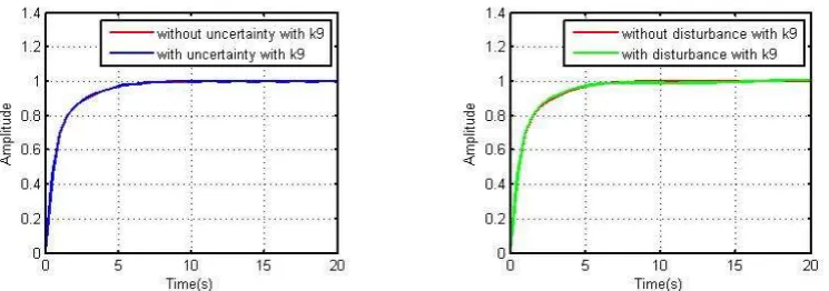
With optimal solution vector k9, the step responses obtained are shown in the Figure 11 and Figure 12.
Figure 11: Step response of the plant using k9 with and without uncertainty
Figure 12: Step response of the controlled plant
using k9 with and without disturbance
[Sharma* 5(4): April, 2018] ISSN 2349-4506
Impact Factor: 3.799
G
lobal
J
ournal of
E
ngineering
S
cience and
R
esearch
M
anagement
Figure 13: Step response of the plant using k16 with and without uncertainty
Figure 14: Step response of the controlled plant
using k16 with and without disturbance
With optimal solution vector k17, the step responses obtained are shown in the Figure 15 and Figure 16.
Figure 15: Step response of the plant using
k17 with and without uncertainty
Figure 16: Step response of the controlled plant
using k17 with and without disturbance
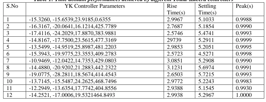
The designed multi-objective controllers based on Youla-Kucera parameterization using MOPSO optimization technique have better tracking performance as compared to controller designed in [6] as observed in Figure 4. The Table 1 provides the time domain performances with different YK controller parameters and controller designed in [6]. Overshoot and undershoot in all the Youla-Kucera controllers are zero.
Table 1: Time domain performances achieved by different Youla-Kucera controllers
S.No YK Controller Parameters Rise Time(s)
Settling Time(s)
[Sharma* 5(4): April, 2018] ISSN 2349-4506
Impact Factor: 3.799
G
lobal
J
ournal of
E
ngineering
S
cience and
R
esearch
M
anagement
13 -14.7554, -19.6819,17.7904,390.5785 2.8650 5.4358 0.9996 14 -13.8287, -16.3983,23.1842,466.9733 3.0065 5.3045 0.9986 15 -15.8988, -20.6454,22.8656,467.2105 2.9599 5.4192 1.0000 16 -11.3925, -13.8834,16.2798,409.8965 3.0940 5.4039 0.9996 17 -11.5601, -11.5371,21.8356,461.9649 3.01407 5.1559 0.9984 18 Controller designed in [6] 57.3726 95.9679 0.9991 The designed multi-objective controllers based on Youla-Kucera parameterization using MOPSO optimization technique have lower rise time, setting time and peak as compared to controller designed in [6] as observed in Table 1. The effectiveness of this novel design approach is tested on a servo system which provides excellent tracking in the presence of uncertainties and disturbances.
REFERENCES
1. M. Jamshidi, L. D. S. Coelho, R. A. Krohling and P. J. Fleming, “Robust Control System with Genetic Algorithm”, CRC Press, 2003.
2. A. Yue and I. Postlethwaite, “Improvement of Helicopter Handling Qualities using H∞ -Optimization”,
IEEE Proc-D Control Theory and Applications, vol. 137, pp. 115-129, May 1990.
3. V. Kucera, “Stability of Discrete Linear Feedback Systems”, Proc. of the 6th IFAC World Congress,
Boston, MA, USA, 1975.
4. D. Henrion, V. Kucera and A. M. Cristobal, “Optimizing Simultaneously over the Numerator and Denominator Polynomials in the Youla-Kucera Parametrization”, IEEE trans. on Automatic Control, vol. 50, no. 9, pp. 1369-1374, 9 Sept. 2005.
5. V. Kucera, “Diophantine Equations in Control-A Survey”, Automatica, vol. 29, no. 6, pp. 1361-1375, 1993.
6. T. Glad and L. Ljung., “Control Theory - Multivariable and Nonlinear methods" Taylor and Francis, 2000.

![Figure 4: Step response of YK controllers designed with MOPSO and method developed in [6]](https://thumb-us.123doks.com/thumbv2/123dok_us/8886992.1823046/5.595.172.428.168.385/figure-step-response-controllers-designed-mopso-method-developed.webp)