Department of Civil Engineering & MBA, Loyola Institute of Technology, Chennai, Tamilnadu, India
Analytical Study on Composite Frames
Archana P 1, Anjughap Priya R 2, Leema Rose A 3
M.E Structural Engineering, Department of Civil Engineering, Valliammai Engineering College, Tamil Nadu, India1
Assistant Professor (O.G), Department of Civil Engineering, Valliammai Engineering College, Tamil Nadu, India2
Associate Professor, Department of Civil Engineering, Valliammai Engineering College, Tamil Nadu, India3
ABSTRACT: This study is an attempt to understand the behaviour of Composite frames with Concrete Filled Steel Tubular Column (composite column) with Steel I- beam by weld connections. A Concrete Filled Steel Tubular (CFST) Column is formed by filling a steel tube with concrete. Circular Concrete filled Steel tubular column is used because it will have excellent mechanical behavior than square CFST Column. Self compacting concrete is used in Steel tubular column because it is a flowing concrete mixture that is able to consolidate under its own weight. The highly fluid nature of SCC makes it suitable for placing in difficult conditions. The frame specimen consists of two CFST Columns and Steel I beam. The design specifications and standards by Euro Code 4 are addressed. Steel I –Beam is used since it can withstand very heavy loads. Hot rolled steel is preferred for composite frames. Abaqus Software is used to investigate the behaviour of composite frames.
KEYWORDS: Composite Frames, Concrete filled steel tubular Column (CFST), Steel I-beam, Self Compacting Concrete, Weld Connections.
I. INTRODUCTION
Composite frame consists of two Concrete filled steel tubular columns (Self compacting concrete) with steel I-beam connected by weld connections. A steel concrete composite column is a compression member which comprises of either a concrete encased hot-rolled steel section or a concrete filled steel tubular section (CFST Column) of hot-rolled steel. In a composite column both the steel and concrete would resist the external loading by interacting together by both bond and friction.
The Usage of composite column (CFST Column) has increased stiffness, strength and it is also leading to reduced slenderness, good fire resistance. CFST structure is a type of the composite steel –concrete. Concrete Filled Steel Tubular members are perceived for their excellent performance resulting to the combination of both Steel and Concrete. When they are used as structural columns, the composite members may be subjected to high shearing force as well as moments under wind or seismic action.
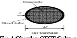
A well designed and properly detailed Composite Column is a structural element that will highlight the Collaborative behaviour of its constituent materials including high cross-sectional stiffness, high compressive strength, large ductility, high tensile resistance of the concrete, high strength to stiffness ratio and light weight construction associated with Steel. The Circular CFST Column is shown in Fig 1.
Fig .1 Circular CFST Column
Department of Civil Engineering & MBA, Loyola Institute of Technology, Chennai, Tamilnadu, India
carrying both bending and shears loads in the plane of the web.
Self Compacting concrete is a flowing concrete mixture that is able to consolidate under its own weight. The highly fluid nature of SCC makes it suitable for placing in difficult conditions .Self compacting concrete is placed or poured in the same way as ordinary concrete but without vibration. It is very fluid and can pass around obstruction and fill all the nooks and corners without the risk of mortar or other ingredients of concrete separating out, at the same time there is no entrapped air. This type of concrete mixture does not require any compaction and it saves time, labour and energy.The surface finish produced by self compacting concrete is exceptionally good and patching will not be necessary.
The CFST Column with Steel I-Beam is connected by welded connections. Welding is a process of joining two pieces
of metal by creating a strong metallurgical bond between them by heating or pressure or both. Welding enables direct
transfer of stress between members eliminating gusset and splice plates necessary for bolted structures. Hence the weight of the joint is minimum. It offers air tight and water tight joining and they enable the connections of
complicated shapes.
The following are the objectives of this study,
To study the behaviour of Composite Frames.
To study the various modes of failure of Composite Frames.
To analyse the model by using Abaqus Software.
II. SCOPE
For high rise buildings the steel concrete composite construction is cost effective.
It has much scope for the use of composite structures in seismic areas.
The CFST column has increased strength for a given cross sectional dimension, increased stiffness, increased
buckling resistance.The ductility index for Circular Concrete Filled CFST Column is higher than Square Concrete Filled Steel Tubular Column.
The use of Self Compacting Concrete has superior strength, durability, improved constructability, improved
structural integrity, uniform surface finish.
III. SPECIFICATIONS
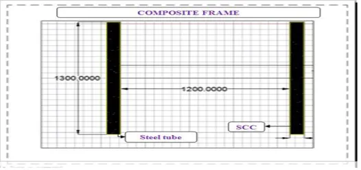
The following are the dimensions of the Composite frame,
(i)The ISMB 150 section is used for steel I-beam. The CFST Column is of 100 mm diameter filled with self
compacting concrete.
(ii) The Setcrete (liquid integral water proofing admixture) is used in self compacting concrete and it is shown in the dotted lines as in Fig 2.
Department of Civil Engineering & MBA, Loyola Institute of Technology, Chennai, Tamilnadu, India
IV. ANALYSIS (ABAQUS SOFTWARE)
4.1GENERAL
1.The Abaqus software for finite element analysis (FEA) is well known for its high performance, challenging
simulations than all other software.
2.The Abaqus does not have built–in units. The user must use consistent units.
3. The Abaqus software consists of three core products: ABAQUS /Standard, ABAQUS /Explicit and ABAQUS
/CAE.
(i)ABAQUS/standard provides ABAQUS analysis technology to solve traditional implicit finite element analyses such as static, dynamic, thermal all powered with the widest range of contact and nonlinear material options.
(ii)ABAQUS /Explicit provides ABAQUS analysis technology focused on transient dynamics and quasi-static analyses.
(iii)ABAQUS/CAE provides a complete modeling and visualization environment for ABAQUS analysis products.
4.2 PROCESSES IN ABAQUS MODEL
The processes in Abaqus model is listed below,
1.Modelling (Creating the geometry)
2.Defining the materials and assigning the Sectional Properties.
3. Assembly
4.Interactions.
5. Mesh
6.Step
7.Boundary Conditions and Loads
8.Run Analysis
9.Visualization (Outputs)
4.3 METHODS OF ANALYSIS
There are three methods of Anlaysis. They are as follows
(1) Interactive
(2) Python script
(3)Analysis Input File
(i) We use Analysis Input File method of Analysis. Here the Analysis Input File is divided into two types. They are Model data and History data.
(ii)The Model data consists of Part, Assembly, model levels, Boundary Conditions etc., The History data is about loadings ,analysis etc.,
4.4 ABAQUS SIMULATION
STEP 1: CREATING A PART
(i)Parts define the geometry of the individual components of your model and, therefore, are the building blocks of an ABAQUS/CAE model. The geometry part is created and it is shown in Fig.3 (a) and (b) respectively.
1. Steel I-beam is used and the width of steel I-beam is 1.2 m and the beam is kept below 500 mm from the
column height.
Department of Civil Engineering & MBA, Loyola Institute of Technology, Chennai, Tamilnadu, India
Fig .3(a) CFST Column Fig .3 (b) Steel I – Beam
STEP 2: DEFINING AND ASSIGNING THE MATERIALS AND SECTIONAL PROPERTIES (i)After creating the part the material has been specified. In the elastic behavior of the materials, the type given is
Isotropic. The young’s modulus and Poisson ratio has been given and for the plastic material behaviour, the yield strain
and plastic strain is mentioned. (ii)The
material has been defined for the following CFST Column and Steel I-Beam. The CFST Column consists of outer steel tube of 2.5 mm diameter and it is filled inside with Self compacting concrete and ISMB 150 is been defined for Steel
I-Beam. The Steel I-Beam and CFST column is viewed in Fig.4 (a) and (b) respectively. (iii)The region has
been selected and it is been assigned.
Fig .4 (a) CFST Column Fig .4 (b) Steel I – Beam
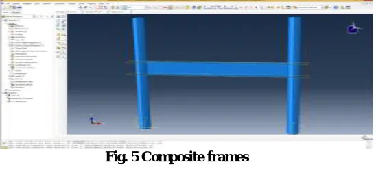
STEP 3: ASSEMBLY
A model can contain many parts, and a part can be instanced many times in the assembly and however, a model contains only one assembly and it is shown in Fig. 5.
Department of Civil Engineering & MBA, Loyola Institute of Technology, Chennai, Tamilnadu, India
analysis they are active. The interactions between CFST Column with Steel I-beam is shown in Fig.6 as below as follows,
Fig .6 Interactions
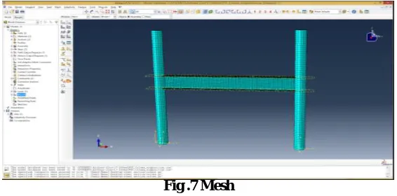
STEP 5: MESH
(i)Hyper mesh is a pre-processing software where you can able to divide the model into number of elements and nodes for a solver to apply the mathematical functions on it . It is shown in Fig.7 as below,
(ii)It is software which is used to divide a particular surface into a number of nodes and do the calculations for a particular problem on those nodes.
(iii)The higher the number of nodes, the more accurate is the solution to the analytical solution .
Fig .7 Mesh
STEP 6: STEP (i)The step sequence provides a convenient way to capture changes in the loading and boundary conditions of the model, changes in the way parts of the model interact with each other, the removal or addition of parts, and any other
changes that may occur in the model during the course of the analysis.
(ii)Here the analysis type is of Static General type and it is shown in below Fig.8
Department of Civil Engineering & MBA, Loyola Institute of Technology, Chennai, Tamilnadu, India
STEP 7: BOUNDARY CONDITIONS
To apply the boundary conditions, a node set needs to be created. Here the condition used is both ends are fixed and it is shown in Fig.9
Fig .9 Boundary Conditions
STEP 8: LOADS
The load plays an prominent role in the Composite frames. The load is given laterally on Composite frames and it is shown in Fig 10 (a) and (b) respectively.
Fig. 10(a) Load Fig. 10(b) Lateral load
STEP 9: Visualization
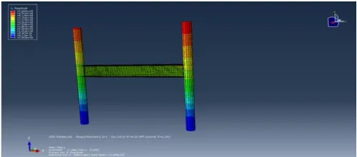
The Visualization will helps us to overlay plot to display plots of substructure data in the same viewport as a plot of the rest of the assembly. The final step of analysis is about getting the analyzed structure to be visualized and it is shown in Fig 11 as below as follows,
Fig.11 Deformed displacements for Composite frame
STEP 10: OUTPUTS
Department of Civil Engineering & MBA, Loyola Institute of Technology, Chennai, Tamilnadu, India
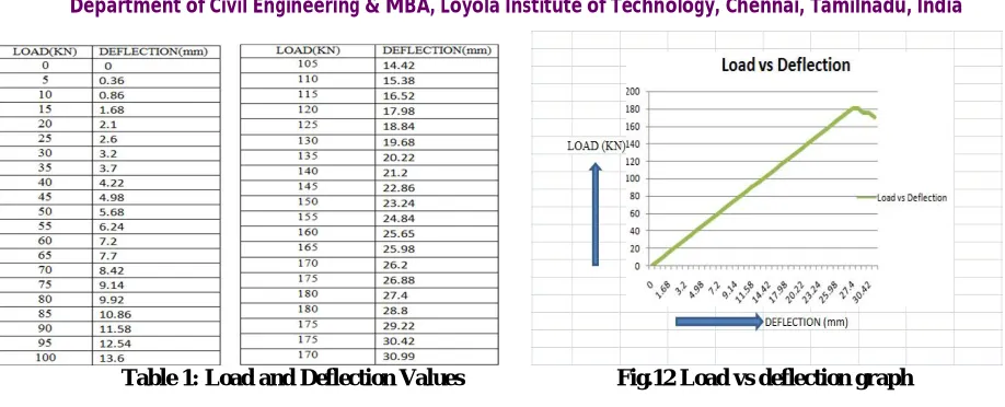
Table 1: Load and Deflection Values Fig.12 Load vs deflection graph
V. CONCLUSION
In this paper it is reported that the behaviour of CFST Column with steel I-beam (Composite frames) by welded connections is studied. The introduced FEA model was able to reasonably predict the lateral load Vs deflection relationship of the Composite frames.
The Composite frames is been analyzed using Abaqus software. From the above study it is concluded that the composite frame section i.e.,(CFST Column with steel I-beam) by weld connections yields by 180 KN. Hence the composite frame section is very efficient The behaviour of composite frames is studied .The Load Vs deflection, graph is plotted. Therefore the Composite frames can be preferred because the composite frames have both concrete and steel. The usage of Circular Concrete filled steel tubular column has efficient strength.
Normally, the Steel frames are ductile in behaviour and concrete frames provide stiffness to resist excessive displacement at the top of the structure. If both the steel and the concrete are used in combination i.e., the Composite frames (CFST column with steel I-Beam) provide greatest stiffness, strength and ductility.
These Composite frames provide effective solution to the problems of design of high rise structures and also they offer
more resistance. Since Composite frames plays an prominent role in the Construction sectors. .
REFERENCES
(1)Aaron w Malone, "Concrete Filled Steel Tubular Column, a finite element study”, Dept of Civil Engineering 2008,Marston Hall Amherst. (2)Suliman Hassan Abdulla,“Behaviour of Concrete Filled Steel Tube under different loading ”. A Thesis Presented to the faculty of the American University Of Sharjah,2009.
(3)Qing Quang Liang (2011), “High Strength Circular Concrete Filled Steel Tubular slender beam –columns Part 1:Numeral analysis”, Journal of Construction Steel Research,Vol.67,Issue 2,pp.164-171.
(4)J.M .Portoles (M.R.2011). “Experimental study on high strength concrete filled circular tubular columns under eccentric loading”.
(5)Qing Quang Liang (2011), “High Strength Circular Concrete Filled Steel Tubular slender beam –columns Part 2:Fundamental behaviour”, Journal of Construction Steel Research,Vol.67,Issue 2,pp.172-180.
(6)Darshikak.Shah,M.D.Vaikil,M.NPatel“Parametric Study on Concrete Filled Steel Tube Column ”.
(7)A textbook on “Composite Structures of Steel and Concrete Volume 1”, by R.P. Johnson, Blackwell Scientific Publications. (8)EN 1992-1-1 – Eurocode 2 – “Design of concrete structures - Part 1-1 General rules and rules for buildings”.
(9)EN 1994-1-1 – Eurocode 4 – “Design of composite steel and concrete structures – Part 1-1 – General rules and rules for buildings”. (10)IS 11384:1985 “Code of Practice for composite construction in Structural Steel and Concrete”.