Design and Analysis of the Multi Storey
Building by Using Y-Shaped Column
Milana K1,Shilpa B S2
P G. Student, Department of Civil Engineering, East West Institute of Technology, Bengaluru, Karnataka, India1
Assistant Professor, Department of Civil Engineering, East West Institute of Technology, Bengaluru, Karnataka, India2
ABSTRACT
:
The architectural requirement leads the designer to think about different shapes and cross sections of the beams, columns, plates. Column is basically a structural member assigned for carrying compressive loads. It carries axial loads from beams and transfers it to footing. The present work deals with the comparative study on behavior of Y-shaped RC column with that of conventional rectangular column for a multi-storey building. The main objective of this study is to study the behavior of a building under the action of Lateral Loads, study the structural behavior of Y-shaped column compared to conventional structure. Software ETABS is made used, and response spectrum method of analysis is carried out to achieve the objective. Design considerations are made according to Indian Standards. The structural efficiency is measured by Storey Displacement, Storey Drift, Storey Acceleration, Storey Forces, Storey Stiffness and Base Shear.KEYWORDS: architectural, footing, Storey Displacement,Storey Drift,ETABS
I. INTRODUCTION
Structural design is a science and art of understanding the behavior of structural members subjected to loads and designing them with economy along with safety, serviceability and as a durable structure. The present dissertation work will be dealing with such a study of structural members made of RCC as it is widely used because of its adaptability.
Column is basically a structural member assigned for carrying compressive loads. It carries axial loads from beams and transfers it to footing. The columns are distinguished in many ways and many types are observed. Based on the slenderness ratio columns are called as short or long columns. The short column fails by crushing and long column fails by buckling. Considering the loading pattern there are axially loaded column, axial column with uniaxial bending, axial column with biaxial bending.
Columns behave differently under static and dynamic loading conditions. The dynamic load consideration is must for places where the seismic activity is high. Therefore when seismic loads are considered the combined approach of ductility and strength must be applied. The wind loads, snow loads, creep, shrinkage and temperature effects are considered where they are necessary. The snow load consideration varies on country to country, and region. It has to be considered as per relevant design codes of relevant codes.
II. SEISMICANALYSISASPERTHEISCODE
When a structure is subjected to earthquake, it responds by vibrating. An earthquake force can be resolved into three mutually perpendicular directions, the two horizontal directions (x and y) and the vertical direction (z). This motion causes the structure to vibrate or shake in all three directions; the predominant direction of shaking is horizontal.
spans, those in which stability for design, or for overall stability analysis of structures. IS 1893 (part-1) code recommends that detailed dynamic analysis, or pseudo static analysis should be carried out depending on the importance of the problem. IS 1893(part1): 2002 recommends use of modal analysis using response spectrum method and equivalent lateral force method for building of height less than 40 m in all seismic zones.
Fig : 1 Seismic Zones
Design Standards
Distinctive nations have their own structural design codes, codes of practice or technical documents which perform a similar function. It is vital for a planner to get comfortable with neighborhood necessities or suggestions concerning right practice.
Particular appropriate codes and measures will be recognized and embraced in plan rationalities as suitable to the basic components. The most recent version of the codes and guidelines will be utilized in plans. All design work shall be based on Indian standards and codes with latest revision, with amendments if any, as on date. Essential Codes and Handbooks for Plan are recorded underneath.
1. IS 456- 2000: Code of practice for plain and reinforced concrete 2. SP 16-1980: Design aid for reinforced concrete to IS 456.
3. IS 875 (part 1)-1987: Code of practice for design loads for buildings and structures-unit weight of building materials and stored material.
4. IS 875 (part 2)-1987: Code of practice for design imposed loads for buildings and structures. 5. IS 875 (part 3)-1987: Code of practice for design wind loads for buildings and structures. 6. IS 875 (part 5)-1987: Code of practice for special loads and load combination.
7. IS 1893 (Part-1)-2002: Indian Standard Criteria for Earthquake Resistant Design of Structures
8. IS 13920-1993: Ductile Detailing of Reinforced Concrete Structures subjected to Seismic Forces - Code of Practice 9. SP34-1987: Handbook on Concrete Reinforcement and Detailing
10. SP 24-1983: Explanatory Handbook on Indian Standard Code of Practice0for Plain and Reinforced Concrete (IS 456:1978).
12. IS 800-2007: General construction in steel.
13. IS 3370:1965: Code of Practice for Concrete Structures for the Storage of Liquids.
Design Data Dead Loads
Dead Loads shall include weight of all structural and Architectural components. Self-weight of the materials shall be calculated on the basis of unit weights given in IS 875.
1. Floor finish of 50mm thickness for Parking and Residential floors: 1.0 KN/m2. 2. False ceiling + ducting + Sprinklers: 0.5 KN/m2.
Live loads
The Imposed loads shall be calculated in accordance0with IS 875-part 2 based on occupancy classification. For multiple occupancies of use in the building shall be referred with the other appropriate comparable occupancy classification0as per table 1 of IS 875-PART 2. Live Loads considered are as follows,
1. Bed Rooms, Wards, Dressing Rooms, Dormitories and Lounges = 2kN/m2 2. Kitchens, Laundries and Laboratories = 3kN/m2
3. Office Rooms and Opt Rooms = 2.5kN/m2 4. Corridors, Passages, Staircases = 4kN/m2
III. MODELLING AND ANALYSIS
The modelling for Beam Column system is done in ETABS as follows. 1. Center-line plan is drawn in auto cad and imported to ETABS. 2. The structure is divided in to distinct membrane element.
3. Gridlines are made for the x, y and z coordinates and the beam, column, slab, are drawn from scratch.
4. Boundary conditions are assigned to the nodes wherever it is required. Boundary conditions are assigned to the bottom of the column i.e. at the ground level where restraints should be against all movement to imitate the behavior of column.
5. Define materials to be used, here we will define concrete, Rebar material using define section properties menu. 6. The geometric properties of the framed sections are dimensions for the beam and column are defined first and then assigned in the grid. Also slab sections are defined first then assigned in the grid.
7. Wind loading and seismic parameters are defined for structure as per the preliminary data. 8. Response spectrum functions are defined as per the seismic consideration and also diaphragms.
9. Static load cases and load combinations are defined and loads are assigning to the joint as they will be applied in the real structure.
10. The model is ready to analyzed forces, stresses and displacement.
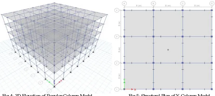
IV. BUILDING DETAILS AND PLAN
Model 1: Conventional building configuration in seismic Zone IV a. Number of stories = G+4
b. C/C distance between columns in X-direction = 4m c. C/C distance between columns in Y-direction = 4m d. Foundation level to ground level = 3m
k. Size of column = 500X500mm l. Size of beam = 230x600mm m. Depth of slab = 150mm n. Seismic zone IV = 0.24 o. Soil Type = II
Model 2: Y-Shaped building configuration in seismic Zone IV a. Number of stories = G+4
b. C/C distance between columns in X-direction = 4m c. C/C distance between columns in Y-direction = 4m d. Foundation level to ground level = 3m
e. Floor to floor height = 3m f. Live load on all floors = 3kN/m2 g. Live Load on Roof = 1.5kN/m2 h. Floor Finish = 1.5kN/m2 i. Concrete = M25 and M30 j. Steel = Fe415 and Fe550
k. Size of columns = 300X300 and 500X500mm l. Size of beam = 230x600mm
m. Depth of slab = 150mm n. Seismic zone IV = 0.24 o. Soil Type = II
Fig 4: 3D Elevation of Regular Column Model Fig 5: Structural Plan of Y Column Model
V. RESULTS AND DISCUSSIONS
a. Storey Displacement
The floor level versus displacement graph is been plotted for the models with regular and Y shaped Columns.
Table 1: Storey Displacement
Storey Regular Column Y Column
4 10.34 10.68 3 9.80 9.72 2 8.76 7.93 1 7.19 5.37 0 0.00 0.00
b. Storey Drift
The floor level versus Storey drift graph is been plotted for the models with regular and Y shaped columns.
Table 2: Storey Drift
Storey Regular Column Y Column
4
0.000203
0.000252
3
0.000372
0.000464
2
0.000519
0.000643
1
0.000618
0.000796
c.
Storey.Acceleration The floor level versus Storey acceleration graph is been plotted for the models with regular and Y shapedcolumns.TABLE 3:STOREY ACCELERATION
Storey Regular Column Y Column
4 454.76 513.66 3 412.31 432.39 2 371.93 376.88 1 329.55 323.74 0 249.66 160.62
d.
Storey ForcesThe floor level versus Storey Force graph is been plotted for the models with regular and Y shaped columns.
Table 4: Storey Forces
Storey Regular Column Y Column
4 194.3822 191.7459 3 415.7758 380.0184 2 607.3115 526.4287 1 767.2616 634.029 0 809.9411 646.8112
e.
Storey StiffnessThe floor level versus Storey stiffness graph is been plotted for the models with regular and Y shaped columns.
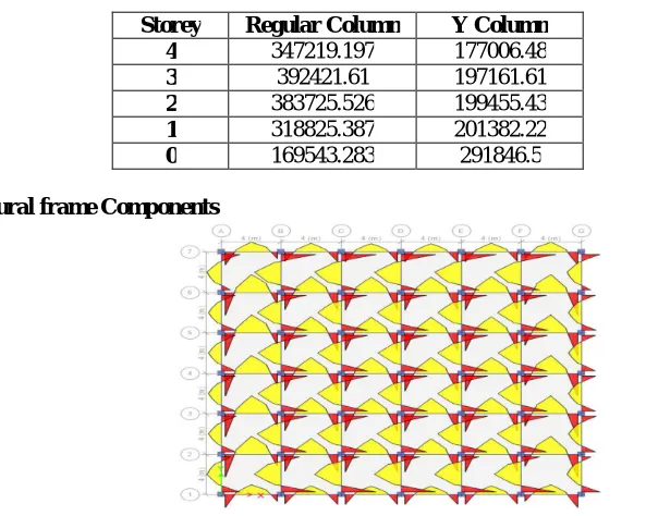
Table 5: Storey Stiffness
Storey Regular Column Y Column
4 347219.197 177006.48 3 392421.61 197161.61 2 383725.526 199455.43 1 318825.387 201382.22 0 169543.283 291846.5
Design of structural frame Components
FIG 6: AXIAL FORCE DIAGRAM IN COLUMN FOR FIG 7: BENDING MOMENT DIAGRAM IN BEAMS FOR Y REGULAR RC BUILDING MODEL SHAPED BUILDING MODEL
Fig 9: Reinforcement Required for Beams in Y Shaped Building Model
VI.CONCLUSION
1. Maximum lateral storey displacement occurs at terrace floor level for all types of structure model.
2. The seismic forces are more concentrated at the base of the building hence the resistive Storey force by the building will be more at the lower storey.
3. Storey stiffness for regular RC building model is higher than that for the Y –shaped building model as in the regular model number of columns are more and the spacing between the columns are also less hence stiffness for the building also increases.
4. The base shear for the regular building model is more than that for the Y- shaped building model.
5. By introducing the inclined support members which will be supported at some intermediate level of the vertical portion of the column other than floor level, it causes the higher moments. If they are not properly balanced along both sides of the column, it makes the design complex. For this reason balanced cantilever ideology is applied in the present dissertation work. The position of inclined support members from both the faces should be balanced by considering loading pattern.
6. The Y-shaped columns can be used for architectural purpose by giving the pleasing appearance to inclined support members, which increases the aesthetic appearance of the structure.
7. As the reinforcement required for Y-shaped building model is less than that of the regular building model it is cost effective than the regular building.
REFERENCES