ABSTRACT
CHIEN-LUNG WU. On Network-Layer Packet Traceback: Tracing Denial-of-Service (DoS) and Distributed Denial-of-Service (DDoS) Attacks. (Under the direction of Dr. Shyhtsun Felix Wu and Dr. Arne A. Nilsson)
The objective of this research is to study the Internet Protocol (IP) traceback technique
in defeating Denial-of-Service (DoS) and Distributed Denial-of-Service (DDoS) attacks.
Tracing attackers is the first and most important step to solve the DoS/DDoS problem. In this
dissertation, two new traceback techniques, PHIL and Intention-Driven iTrace, are proposed
and evaluated. Based on the IPSec infrastructure, previously, the Decentralized Source
Identification for Network-based Intrusions (DECIDUOUS) module has been implemented and
evaluated. However, in order to trace attack sources across different administrative domains
securely, the notion of Packet Header Information List (PHIL) for IPSec is proposed to
enhance DECIDUOUS module. Second, it is shown, in this thesis, that the iTrace (ICMP
traceback, being standardized in IETF) has some serious drawbacks. To overcome these
drawbacks, the Intention-Driven iTrace (ID-iTrace) and the Hybrid iTrace schemes are
proposed. Our simulation results confirm that the original iTrace scheme is not able to handle
low attack traffic well. From our simulation, the Hybrid iTrace scheme is evaluated and
To my Lord,
to my parents,
to my wife Mei-Yu,
PERSONAL BIOGRAPHY
CHIEN-LUNG WU was born in Taichung, Taiwan. He attended ChungYuang
Christian University from 1983 to 1987, where he graduated with a B.S. degree in Electrical
and Computer Engineering. After graduation, he entered Siemans Inc. in Taiwan as a hardware
engineer and worked in R&D department for five years. Chien-Lung came to the United States
of America in the fall of 1994 to study for his master’s degree in Electrical and Computer
Engineering at Syracuse University, N.Y. He obtained his M.S. degree in Electrical
Engineering in 1995, and M.S. degree in Computer Engineering in 1996. In 1997, he
continued his Ph.D. studies in the department of Electrical and Computer Engineering at North
Carolina State University, Raleigh. While attending North Carolina State University, he was
employed by Fujitsu Networks as a research assistant in mobileIP and Quality of Service
Routing (QoSR) projects. From 1998 to 2001, he was a research assistant to Dr. Felix Wu,
working on the DECIDUOUS and FNIISC projects. In 2002, he joined Delta Network as a
Senior Software Engineer. His current research interests are attack-tracing mechanism design,
network security and management, network routing protocol design, and embedded system
ACKNOWLEDGEMENTS
First, I would like to thank my advisor Dr. Shyhtsun Felix Wu. He taught me the
essence of network security and the principles of research, and guided me in finishing this
dissertation. I will never forget his encouragement and support.
I sincerely thank my committee members, Dr. Arne A. Nilsson, Dr. Edward Gehringer,
and Dr. George N. Rouskas. Their valuable and constructive suggestions helped me to improve
my dissertation. I am grateful for their time and efforts in assisting me during this process.
I would like to thank my colleagues: Xialiang Zhao, Zhu Fu, Ho-Yen Chang, Feiyi
Wang and others. Many discussions, sharing, encouragement, and suggestions gave me great
help in my studies.
I also want to thank my brothers and sisters from the Raleigh Chinese Christian Church.
Their continuous support and prayers encouraged me to overcome a lot of frustrations in my
life.
I would like to thank Dr. Albert Shih, Dr. Raymond Chen, and Dr. S. W. Kiu. They
gave me many suggestions and advice, and encouraged me to finish this dissertation. Thank
you for your support. A special word of thanks for Doris Kiu: I will never forget your help,
teaching, and encouragement.
I know I owe my family a lot. My parents and parents-in-law have always given me
their love and support all my life. My sisters and brothers have also given me all their support
over the years. And my dear wife, Mei-Yu, always supports and continually prays for me. Over
the years, her encouragement, patience, and love are always with me. I dedicate all my love
TABLE OF CONTENTS
LIST OF FIGURES ... VIII
LIST OF TABLES ...X
CHAPTER 1
INTRODUCTION ... 1
1.1 PROBLEM DEFINITION AND RESEARCH MOTIVATION... 1
1.1.1 DoS and DDoS attacks ... 1
1.1.2 Source accountability ... 2
1.1.3 IP traceback problem ... 2
1.1.4 Research objective... 2
1.2 IPTRACEBACK SOLUTIONS: OUR PROPOSALS... 3
1.3 RESEARCH CONTRIBUTIONS... 3
1.4 DISSERTATION OUTLINE... 4
CHAPTER 2
RELATED WORKS ... 5
2.1 INGRESS FILTERING... 5
2.2 ATTACK-LINK IDENTIFICATION... 6
2.2.1 Link testing... 6
2.2.2 Controlled flooding... 7
2.2.3 IPSec-based IP traceback... 7
2.3 LOGGING-BASED IP TRACEBACK... 9
2.4 SAMPLING-BASED IP TRACEBACK... 10
2.4.1 Probabilistic Packet Marking (PPM) scheme ... 11
2.4.2 ICMP traceback (iTrace) scheme ... 15
2.5 SUMMARY OF THIS CHAPTER... 16
CHAPTER 3
IPSEC-BASED SOURCE TRACING ... 18
3.1 BRIEF INTRODUCTION TO IPSEC PROTOCOL... 18
3.2 THE PRINCIPAL PROBLEM OF THE IPSEC PROTOCOL... 20
3.3.2 Challenges for DECIDUOUS module... 25
3.4 PHIL AND PHIL-APIS... 25
3.4.1 Motivations... 26
3.4.2 The design and Implementation of PHIL and PHIL-APIs ... 26
3.4.3 PHIL-API Suite ... 28
3.4.4 The Evaluation of the PHIL implementation... 33
3.5 PHIL SWITCHING... 36
3.5.1 The capabilities of the PHIL-switching... 37
3.5.2 The design and implementation of the PHIL-switching... 38
3.5.3 The evaluation of PHIL-switching implementation ... 40
3.5.4 Applications of PHIL-switching technique ... 42
3.6 SUMMARY OF THIS CHAPTER... 43
CHAPTER 4
ITRACE-BASED SOURCE TRACING... 45
4.1 ICMP TRACEBACK SCHEME -- OVERVIEW... 46
4.1.1 The format of iTrace message ... 46
4.1.2 The authentication mechanism of iTrace message ... 48
4.1.3 The operation of ICMP traceback... 49
4.2 POTENTIAL PROBLEMS OF THE ICMP TRACEBACK... 52
4.3 SOLUTION:INTENTION-DRIVEN ITRACE SCHEME... 52
4.3.1 The general architecture of Intention-Driven iTrace scheme ... 55
4.3.2 The design of the Intention-Driven iTrace scheme ... 56
4.3.3 Main concerns about the Intention-Driven iTrace design ... 58
4.4 THE MORE EFFICIENT SOLUTION: THE HYBRID ITRACE SCHEME... 59
4.4.1 The detailed design of the Hybrid iTrace scheme ... 59
4.5 THE DISTRIBUTION OF THE INTENTION-BIT... 65
4.6 SUMMARY OF THIS CHAPTER... 67
CHAPTER 5
LIGHT-WEIGHT AUTHENTICATION FOR ICMP
TRACEBACK ... 69
5.1 THE LIGHT-WEIGHT AUTHENTICATION SYSTEM... 70
5.2 THE EVALUATION OF THE LIGHT-WEIGHT AUTHENTICATION SCHEME... 73
CHAPTER 6
SIMULATION-BASED EVALUATION ... 75
6.1 THE SIMULATION ENVIRONMENT... 76
6.2 THE MEASUREMENTS OF THIS SIMULATION... 77
6.3 STRATEGY I: THE COMPARISON BETWEEN THE ORIGINAL ITRACE AND THE ID-ITRACE SCHEMES... 78
6.3.1 Simulation results and analysis... 79
6.4 STRATEGY II:THE EVALUATION OF HYBRID ITRACE SCHEME... 83
6.4.1 Simulation results and analysis... 84
6.5 SUMMARY OF THIS CHAPTER... 88
CHAPTER 7
CONCLUSION AND FUTURE WORK ... 91
7.1 CONTRIBUTION SUMMARY... 92
7.2 FUTURE WORK... 93
List of Figures
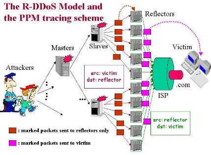
Figure 2. 1 – The Reflective DDoS attack model and PPM tracing scheme: the PPM scheme
is not able to trace reflective DDoS attacks. ... 14
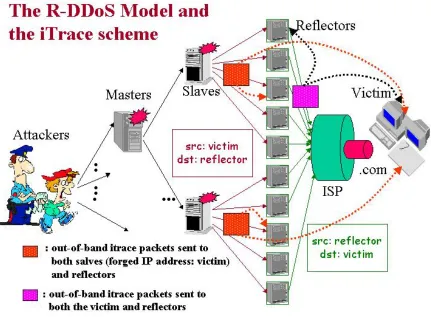
Figure 2. 2 – The Reflective DDoS attack model and the iTrace scheme: the iTrace scheme can trace reflective DDoS attacks... 16
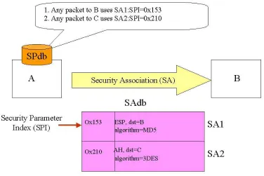
Figure 3. 1 – The Security Association (SA)... 19
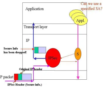
Figure 3. 2 – The IPSec header is dropped after IPSec process. ... 21
Figure 3. 3 – (a) The concept of CutSet (b) The detection algorithm... 23
Figure 3. 4 – PHIL and PHIL-API design concept... 28
Figure 3. 5 – The configuration for PHIL evaluation and PHIL testing plan... 34
Figure 3. 6 – DECIDUOUS tracing module with PHIL-switching support ... 37
Figure 3. 7 – PHIL-switching function block. ... 39
Figure 3. 8 – The test cases for evaluating PHIL- switching... 41
Figure 3. 9 – The example of PHIL-switching within the local NCSU domain... 43
Figure 4. 1 – The iTrace Message Format ... 47
Figure 4. 2 – The process of generating an iTrace packet. ... 50
Figure 4. 3 – iTrace packets generated by routers and collected by a logger. ... 51
Figure 4. 4 – The Intention-Driven iTrace scheme... 54
Figure 4. 5 – Decision and iTrace Generation modules of the ID-iTrace scheme... 56
Figure 4. 6 – The Hybrid iTrace scheme: Traffic-Separation mode... 62
Figure 4. 7 – The Hybrid iTrace scheme: Probability-Separation mode. ... 64
Figure 4. 8 – (a) “No Export” community (b) Our proposed iTrace community. ... 66
Figure 5. 1 – The pre-computed digest table. ... 70
Figure 5. 2 – The light-weight authentication design for iTrace ... 71
Figure 6. 1 – The simulation test-bed ... 76
Figure 6. 2 – An attack path... 79
Figure 6. 3 – The comparison of the usefulness of iTrace messages in different iTrace schemes. ... 81
Figure 6. 4 – The comparison of the usefulness of iTrace messages for another path. ... 82
Figure 6. 5 – The comparison of “value” among different schemes on R112... 83
Figure 6. 6 – The percentage of useful iTrace vs. variable background traffic rates... 85
Figure 6. 7 – The number of useful iTrace packets vs. attack rate with constant background traffic=100k, the value of q=0.75. ... 86
Figure 6. 8 – The accumulation values v.s timing ... 87
List of Tables
Table 3. 1: The results of evaluating IPSec/PHIL overhead... 35
Table 3. 2: The test results of PHIL-switching. ... 41
Table 4. 1: List and description of iTrace message tags ... 48
Chapter 1
Introduction
In today’s internet, one of the thorniest problems in dealing with Denial-of-Service
(DoS) and Distributed Denial-of Service (DDoS) attacks is to trace the attack sources, given
the present state of the internet. There is an urgent need to thoroughly understand the
problems involved and to build an efficient mechanism to address the tracing issues. This
chapter presents the research motivation and outlines the overall structure of the whole
project.
1.1
Problem definition and Research Motivation
1.1.1
DoS and DDoS attacks
A denial-of-service (DoS) attack [1] is an attack in which intruders intentionally take
up much of the shared resources of a remote host or network, and as a result, legitimate users
are denied from using network resources. The distributed denial of service (DDoS) [2, 3]
attack is the distributed version of DoS attacks: the attackers compromised hundreds or
thousands of machines and controlled those compromised machines to attack targets
simultaneously.
Both DoS and DDoS attacks exploit the vulnerability of today’s network
infrastructure [4, 5, 6]. In the past several years, DoS/DDoS attacks have increased in
frequency, severity, and sophistication [7, 8]. The 2002 CSI/FBI Computer Crime and
Security Survey results [9] show that over 55% of respondents have been hit by DoS/DDoS
known February 2000 DoS attacks [10], bringing down commercial websites such as Yahoo,
eBay, Amazon, CNN, and ZDNet, are a painful reminder that DoS and DDoS attacks have
become some of the severest network security problems.
1.1.2
Source accountability
The nature of IP protocol and IP routing only depends on the destination address but
not the source IP address [11, 12] to route IP packets. Hence, the attackers can put any
spoofed or forged IP address on the source address field of IP header to deceive intrusion
detection systems (IDS) and victims. Therefore, a victim cannot count on using the
information in the received attack packets to discover the identity of the original attack
sources. This is the source accountability problem [13], which makes it very difficult to trace
the attacker(s).
1.1.3
IP traceback problem
The IP traceback is a special mechanism that enables victims or intrusion detection
systems (IDS) to trace attacks back to their origins and hopefully, stop attackers at the attack
sources [6, 14, 15]. However, this is difficult to do because of the present state of source
accountability (un-trusted source IP addresses). How to solve this IP traceback problem is
one of the big challenges in network security research, especially in the area of eliminating
DoS/DDoS attacks.
1.1.4
Research objective
Our objective is to design and develop a possible and practical traceback mechanism
reasonable and small enough domain, and then stop the attacks right at the sources. In
particular, we focused on DoS/DDoS attacks attempting to saturate network resources so as
to prevent legitimate requests from being served.
1.2
IP Traceback Solutions: our proposals
In this dissertation, we developed and evaluated two new techniques to enhance the
performance of IP traceback systems. The first approach is the IPSec-based source tracing
scheme. As the IP security protocol (IPSec) [16] becomes a de facto standard, it is possible
and convenient for us to develop a trace back mechanism by utilizing the IPSec framework.
The second approach is the ICMP traceback scheme [17]. Using an efficient packet sampling
mechanism, the intermediate routers can provide useful information for the victim to
construct an attack route path. When victims or Intrusion Detection Systems obtain the
information of the attack paths, we are able to trace the attackers and then stop the attacks
immediately.
1.3
Research Contributions
The contributions of this thesis are:
The design of Packet Header Information List (PHIL) and PHIL-APIs extends the
utilization of the IPSec protocol and makes application-to-application security
possible.
The PHIL-switching technique provides a solution of tracing attack sources across
The ICMP traceback (iTrace) [17] mechanism, one of the sampling-based
approaches, is studied. Its weaknesses are investigated and simulated in our test bed.
The Intention-Driven iTrace (ID-iTrace) [18] and Hybrid iTrace schemes are
developed to enhance the original iTrace scheme at a practical level thus
eliminating many of its weaknesses.
1.4
Dissertation Outline
This dissertation is divided into seven chapters. Chapter 1 introduces the IP traceback
problem of DoS/DDoS attacks and the motivation of this research. Related works are
provided in Chapter 2. Chapter 3 presents the IPSec-based approach. Chapter 4 introduces
the ICMP traceback (iTrace) and presents our enhanced versions: the Intention-Driven iTrace
(ID-iTrace) and the Hybrid iTrace schemes. A light-weigh authentication mechanism for
iTrace/ID-iTrace is demonstrated in Chapter 5. Chapter 6 describes our simulation processes
and shows our simulation results. Chapter 7 summarizes the contribution of this dissertation
Chapter 2
Related Works
In this chapter, a wide spectrum of research works [6, 17, 19, 20, 21, 22, 23, 24, 25]
conducted in the area of IP traceback issues is reviewed and analyzed. An understanding of
various approaches, including the ingress filter technique, attack-link identification
(link-testing, control flooding, and IPSec-based tracing), logging-based scheme (logging and
hash-based logging), and sampling-hash-based scheme (probabilistic packet marking scheme and ICMP
traceback scheme), provides us with background knowledge and also shows us the research
directions in this field.
2.1
Ingress filtering
The ingress filtering approach [19] is proposed to prevent an attacker within an
originating network from using forged IP addresses. This technique requires that a router has
both sufficient power to examine the source address in every single packet and enough
knowledge to distinguish between legitimate and illegitimate addresses. Hence, it is better to
configure the ingress filtering in customer networks or at the border of internet service
providers (ISP), where the address ownership is easy to maintain. Any packet with an IP
address which cannot maintain the ownership or doesn’t have the ownership will be dropped.
Thus the ingress filtering approach greatly reduces forged IP problems and also minimizes
the possibility of flooding targets with forged addresses.
However, there are several concerns about this scheme. First, the examination of
every single packet will definitely degrade network performance. This is the major concern
technique depends on the widespread use of this method. If some ISPs do not cooperate to
provide this feature, the source IP still cannot be trusted because it is unable to know whether
the packet comes from filter-enabled or filter-disabled domains. Third, even though all ISPs
have turned on the ingress filtering, DoS/DDoS attackers still are able to use forged IP
addresses which are on the list of ISP’s ownership.
2.2
Attack-link identification
This category of traceback schemes examines upstream links in order to identify
attack flows. After each attack flow (from the victim’s domain toward attack domains) has
been confirmed, the attack path(s) can be discovered, and as a result, the attack sources can
be located and then the attacks stopped. To examine the attack links, there are two proposed
methods. One is to flood upstream links. If the attack decreases when one of the links is
flooded, this link can be identified as an attack link. Link testing and controlled flooding [20]
use this method to trace attack sources. Another approach which utilizes link authentication
is the one used by IPSec-based tracing [21]: if attack packets come from an authenticated
upstream link, this authenticated link is an attack link
2.2.1
Link testing
Link testing is a way of discovering the domain from which the attack packets
actually originated by examining upstream links. However, this technique requires the attack
flow to be continuous for a period of time. Once the link is identified, the victim will inform
its upstream ISP. The upstream ISP will repeat this process by testing each of its upstream
recursively until the attack flow is isolated to a stub network. Once this attack domain is
located, an investigation can proceed internally to discover the true attacker(s).
This approach has a few problems. First, it relies on individuals to carry out the link
testing manually. Second, if any ISP or domain between the true attacker and the victim
refuses to cooperate or simply does not have the knowledge or manpower to cooperate, it is
impossible to proceed beyond that point. Thus, this method relies on the fact that all ISPs
between the attacker and victim are able and willing to cooperate.
2.2.2
Controlled flooding
One extension of link testing that can be performed automatically by the victim
without the aid of intermediate ISP’s is called controlled flooding [20]. The goal of
controlled flooding is to recursively identify which upstream links are carrying the attack
traffic by flooding all upstream links and analyzing the effect of this flooding on the attack
flow. If flooding a certain link causes the attack flow to decrease, this link is probably being
utilized by attackers. This method has an advantage over traditional link testing in that the
victim can use it with no intervention on the part of intermediate ISPs. The fundamental flaw
in this approach is that it requires flooding another domain’s network in order to do the link
testing. This, in itself, can be construed as a DoS attack.
2.2.3
IPSec-based IP traceback
Node-to-node authentication [26, 27], one of the functions of IPSec, provides an
alternative way to identify attack links. Since IPSec [16] was widely deployed and became a
infrastructure. For example, if an authenticated tunnel from A to B is set up, one can be sure
that any packet received by B from this tunnel is routed by node A. If someone applies this
concept to trace attacks, then node A can be identified as the node which routes the attack
packets. Therefore, if IPSec tunnels are set up between the victim and possible nodes, one is
able to identify attack paths and ultimately locate attack sources. The Decentralized Source
Identification for Network-based Intrusions (DECIDUOUS) project [21] utilized this idea to
implement a traceback mechanism which was proved to be effective in locating attack
sources.
Although the IPSec-based traceback mechanism can finally identify the attackers,
there exist drawbacks in this approach. First, any IP traffic, including attack traffic and
innocent traffic, would be pushed into IPSec tunnels for identifying attack flows. This
method definitely affects and degrades network performance, especially in a high-speed
network. In the case of flooding-style DDoS attacks, the situation becomes worse. Second, in
general, the victim domain doesn’t have any topology information of the entire Internet.
Where and when to set up IPSec tunnels is a major concern. Last, if any transit routing
domain cannot cooperate, this approach will not work.
On the other hand, if the suspect domains can be narrowed down to a small area (for
instance, a university network domain), utilizing the authenticated tunnels to trace true
attacks is still a valuable approach. Moreover, within a local administration domain, the
network performance will not be greatly affected. Also the network topology within a local
administration domain is known and as a result, someone can pre-setup IPSec tunnels to
improve the identification performance. Furthermore, The PHIL (Packet Header Information
allow local administrators to set IPSec tunnels dynamically and automatically, thereby
enhancing the tracing capability of the IPSec-based traceback mechanism. A detailed
description of the IPSec-based traceback scheme and PHIL/PHIL-switch enhancement is
presented in Chapter 3.
2.3
Logging-based IP traceback
Another category of IP Traceback solutions employs logging scheme at routers,
which store information about forwarded packets. Later on, the victim of an attack can query
a specific router to find out whether that router forwarded a specific packet. This approach is
limited in practice due to the large storage requirement involved for any given router; this
method also requires a long period of time and special schemes to query and analyze these
logged data.
The hash-based IP traceback technique [30, 31] is a new log-based approach to
address the space requirement, query overhead and susceptibility to DoS attack. Instead of
storing the entire contents in the packet, which would require 20 to 1,500 bytes of storage per
packet, only a 32-bit digest of specific packet-header fields is stored. Since this digest must
be identical for a single packet traversing multiple routers, any fields in the packet header
that may change from router to router (such as the TTL, checksum, type of service (TOS) and
IP options) must be ignored. To compensate for the probability of a collision, a special data
structure called Bloom filter [30] is utilized to store the digest information. However, instead
of computing only a single digest, a Bloom filter computes k digests using k independent
hash functions, each with a 32-bit uniform output. The output digests are used as indices of
(initially, all positions are set as 0). Whether or not a certain packet has been forwarded by a
particular router can be determined if all k positions in the Bloom filter are set as 1.
The problem with this approach, however, is that even under the above conditions it
is possible to get a false positive from the data. Because the Bloom filter has limited space
and each forwarded packet occupies k entries, the rate of false positives increases as more
entries are marked with each forwarded packet. This limits the usefulness of the hash-based
solution. Another disadvantage is the problems it creates for storage. If the Bloom filter
which occupies approximately 512MB at every router is kept resident in memory, it will
occupy space that routers normally reserve for storing received prefixes from BGP. An
alternative will be to store the data in a secondary storage medium, such as a hard drive. The
seek times and processor overhead to fetch data can significantly reduce the performance of
the router.
2.4
Sampling-based IP traceback
This scheme, unlike other schemes which trace attacks in every single packet, only
samples certain packets based on a randomly sampling scheme; these sampled packets carry
important path information for the victim or the Intrusion Detection system to discover attack
sources. Regarding the method of conveying path information, there are two categories of
sampling-based approaches. One is the probabilistic packet marking [6, 32, 33] scheme
which provides in-band path information by modifying IP header fields to encode path
information. Another approach is the ICMP traceback [17] scheme which copies the sampled
Using the sampling scheme is a feasible solution to enhancing the efficiency of the
traceback mechanism while minimizing the adverse effect on network performance. Given
the current state of heavy network traffic, sampling-based scheme can be even more effective
if we can optimize the sampling probability.
2.4.1
Probabilistic Packet Marking (PPM) scheme
This scheme asks each intermediate router to randomly sample packets in a
probability p and then encode its identification (router ID) into these sampled packets. Each
marked packet, like normal packets, will be forwarded to the destination address described in
the IP header. After the destination host receives these marked packets, it can decode these
packets to obtain each router’s identification and figure out attack paths. For example, the
destination host can examine suspect attack packets and discover possible attack paths and
ultimately locate the true attackers.
There are several proposed approaches to implement the PPM scheme. The first one
is called node sampling [6, 33], proposed by Savage in 2000. In this technique, an upstream
router will randomly select packets with probability p and mark these packets by inserting its
IP address in a special 32-bit field of IP header before forwarding this packet. Since each
upstream router forwarding packets to the destination host has a probability of p to mark a
packet, the router information could be overwritten by other routers [6]. Therefore, the
probability for a victim to receive a marked packet from a router, which is d hops away from
the victim, can be expressed as (p* (1 – p) d – 1) -- a function of distance d (in terms of hops).
This probability will significantly decrease as the distance d increases. Thus to correctly
essence this will pose a serious problem. Furthermore, since this method just provide node
identification, it is hard for the destination host to figure out the sequence of intermediate
routers and then to discover correct routing paths.
To address this issue, Savage [6, 32] also proposed the edge sampling technique
where an edge (a link between two routers) is stored into the marked packet along with the
number of hops between the routers. This would require 72 bits of additional space to store
two 32-bit IP addresses and one 8-bit distance field -- a significant increase when compared
to node sampling. To solve the space problem, this technique uses an encoding scheme that
allows the 72 bits of data to be encoded and then fragmented into several pieces. After the
destination host receives enough marked packets, it is able to reassemble these pieces to
obtain the edge identification.
Although the edge sampling approach solves the sequence and space problems, there
are several drawbacks to this approach. First, it suffers from the extremely high process
overhead required in marking packets. In addition, since the edge identifier is stored in the
IP identification field of IP header, this mechanism would invalidate any fragmented IP
packets. Furthermore, because the edge-id is fragmented to reduce space requirements, the
edge sampling technique requires more marked packets to discover the attack paths. Another
flaw in both edge and node sampling approaches is the lack of protection in cases when
malicious users mark packets with false data.
The advanced marking scheme [22, 34] is proposed to address the overhead and
authentication issues of edge sampling scheme. Instead of generating a 64-bit edge-id that
later gets fragmented, this scheme simply uses two unique hash functions to compute the
IP addresses and return 11-bit hashes. These hashes are then XOR’d together to generate the
edge-id. This edge-id is stored in the IP identification field (16 bits) as in the edge sampling
approach, and the remaining 5 bits are used for the distance value (hop count). After
receiving these marked packets, the destination host can compute the hash functions to
identify nodes which marked these packets and use the distance value to decide the sequence
of nodes of an attack path.
The Advanced Marking Scheme still does not provide protection from attempts to
confuse path reconstruction by overwriting legitimate markings with garbage or false
markings. Since all routers and the victim’s path reconstruction tool use the same set of hash
functions, these functions are easily accessible to attackers. An attacker can use the same
hash functions to generate false markings to interfere with the process of path discovery. To
solve the authentication problem, the authenticated marking scheme [22, 34], an extension of
advanced marking technique, adds functionality for the end host to authenticate incoming
marked packets. If a marked packet fails to be authenticated, it will be dropped. Therefore,
the false marked packets which are generated by malicious users cannot prevent end hosts
from discovering routing paths.
Even though the advanced/authenticated marking scheme solves many issues of the
original edge sampling technique, it still introduces extremely high overhead into marked
packets. In order to discover routing paths efficiently, this scheme requires the sampling
probability on the order of 1/25 to 1/10. This means that on average for every 25 forwarded
packets one packet (marked packet) has to suffer processing delay before it can be forwarded.
sampling) is not able to handle reflective DDoS [35] attacks. Since this scheme encodes path
information into the marked packets and these packets are only forwarded to a destination
host, the victim can only receive marked packets from routers between reflectors and victim:
there is no way for the victim to receive any marked packet from the true attack sources,
which are beyond reflectors. Therefore, it is impossible for the victim to trace the true
attacker(s) in reflective DDoS attacks. Figure 2.1 explains the problem in tracing reflective
DDoS attacks.
2.4.2
ICMP traceback (iTrace) scheme
The ICMP Traceback (iTrace) [17] is another type of sampling-based tracing schemes,
proposed by S. M. Bellovin in 2000. The iTrace scheme randomly selects and copies a packet
in probability p and then the original packet is forwarded immediately; as a result, the
selected packet will not suffer too much processing delay. Once a packet is selected, a
special ICMP packet, called iTrace message or iTrace packet, is generated and sent to the
host which is the destination address in the IP header of the selected packet. This message
contains useful information such as the pair of IP address and MAC address of both the
upstream and downstream links of the router that selected the packet. In addition, the
selected packet’s source and destination addresses and a portion of payload are included for
the end host to analyze in its endeavor to discover attack paths. Last, the iTrace message
contains optional authentication messages to prevent a malicious user from forging iTrace
messages.
Until today the iTrace approach is the only proposed scheme that can handle
reflective DDoS attacks [35]. Since this scheme copies the source and destination IP
addresses from the selected packet, it is possible to send the iTrace messages for both the
source and destination hosts, instead of sending iTrace messages for only the destination
machine. Therefore, the victim is able to receive iTrace messages from routers beyond
reflective routers and locate the true attacker(s). Figure 2.2 illustrates how the iTrace scheme
solves the tracing problem of reflective DDoS attacks. The detailed discussions about iTrace
Figure 2. 2 – The Reflective DDoS attack model and the iTrace scheme: the iTrace scheme can trace reflective DDoS attacks.
2.5
Summary of this chapter
In this chapter, we reviewed and analyzed several proposed solutions of IP traceback
issues. From these reviews, we realize that when we design a tracing mechanism, how to
maintain network performance is as important as how to trace attacker(s). For example, the
ingress filter technique can reduce problems of forged IP; however, many ISPs will not adopt
it because of the concern of degrading network performance. How to trace attacker(s)
efficiently without sacrificing network performance is today’s research focus in solving IP
probability p to provide tracing information, instead of checking every single packet, might
be a good approach to deal with both tracing efficiency and network performance.
Since DDoS and reflective DDoS attacks have become the method of choice for
attackers, how to handle these types of attacks is also a major concern in devising traceback
schemes. Within today’s proposed solutions, only the ICMP traceback (iTrace) scheme, one
of the sampling approaches, can solve the tracing problem of DDoS and reflective DDoS
attacks. Therefore, we choose the iTrace scheme as a base to solve the IP traceback problem.
However, the iTrace scheme is still not able to provide a complete solution. In the
distributed style of attacks, to sample attack packets near the victim is easy because there are
huge volumes of attack packets; but to sample packets near the attacker may be difficult
because of the small amount of attack packets. This limitation of the iTrace scheme can be
solved by incorporating the IPSec-based tracing scheme into the solution, since the IPSec
protocol is widely employed in today’s internet. The traceback scenario could be: utilize the
iTrace scheme to narrow down the suspected attack domains and use the IPSec-based tracing
scheme to locate the true attack source(s) in each suspected attack domain. In this
dissertation, we will focus on both IPSec-based and iTrace-based approaches to understand
both schemes’ advantages and limitations, and propose our enhancements to solve the IP
Chapter 3
IPSec-Based Source Tracing
Node-to-node authentication provides a means for us to solve the principal problem in
tracing attack sources. Through the authentication mechanism, if one node receives an
authenticated packet, this node can be sure that the authenticated packet is forwarded by
another node. Thus if we set up an authentication tunnel (virtual tunnel) between a victim and
a router and the victim still receives attack packets which are authenticated, we can be certain
that this router belongs to an attack path. By repeating this process, ultimately we are able to
trace attack sources and then stop attacks.
The IPSec protocol provides node authentication functionality as a default. Since the
IPSec protocol suite [16] has been standardized and is widely employed, it is convenient for
us to develop a tracing mechanism on top of the IPSec infrastructure. The Decentralized
Source Identification for Network-based Intrusion (DECIDUOUS) [21] is a tracing
mechanism which is developed by utilizing node authentication of the IPSec. In this chapter,
we present the design of the DECIDUOUS tracing mechanism and investigate the limitations
of this approach in tracing attacks across different administration domains. Then the Packet
Head Information List (PHIL) and the PHIL-switching techniques are proposed and
developed to enhance the tracing ability of DECIDUOUS.
3.1
Brief introduction to IPSec protocol
The IPSec protocol [16, 36] provides security functionality, including authentication
can utilize the IPSec to provide security services. There are three principal components in
IPSec suite:
• The Authentication Header (AH) protocol [26] provides only the function of
authentication to IP packets.
• The Encapsulating Security Payload (ESP) protocol [27] provides the encryption and the authentication (option) to IP packets.
• The Key management [37] provides the negotiation of connection parameters, such as the key, the communication protocols (ESP or AH), and the algorithms (MD5, HMAC-MD5,
3DES, etc.)
The important concept of the IPSec [16] is the security association (SA) between two
network entities. An SA is a one-way relationship that affords security service to traffic. As
shown in Figure 3.1, if node A wants to build up an IPSec tunnel with node B (A Æ B), A
and B should negotiate an SA to describe security protocols (AH or ESP) and algorithms to
authenticate or encrypt data. All SAs are put into the SA database (SAdb).
How to process IP packets depends on security policies, which are stored in the
security policy database (SPdb). For example, if an incoming packet matches one of the
policies in node A (see Figure 3.1), a related SA (security protocols and algorithms) from the
SAdb will be used to authenticate or encrypt this packet. If this packet does not match any
policy, it will be forwarded as normal traffic.
Node authentication, one function of the IPSec suite, provides a mechanism to trace
attack sources. If there is an IPSec tunnel from node A to node B, a trusted relationship
between node A and node B can be maintained. For example, if B received an IP packet from
this IPSec tunnel (AÆB), one thing can be sure that this IP packet was really forwarded by A.
If B can set up IPSec tunnels with other upstream nodes in the same way, B is able to identify
where the attack packets are coming from, and thereby locate and stop attacks. The
DECIDUOUS [23, 40] tracing module utilizes this technique to discover attack paths and
locate attack sources.
3.2
The principal problem of the IPSec protocol
Although the IPSec can provide node authentication, the IPSec header information
(secure information) will be dropped after the IPSec process is completed (See Figure 3.2.);
information. However, such information is extremely useful to applications like Intrusion
Detection Systems (IDS) [39, 40] for identifying attacks and to applications like SNMP [41,
42] for network management. Given the state of current IPSec implementations, there is a
need to bridge the big gap between applications and IPSec protocol
Figure 3. 2 – The IPSec header is dropped after IPSec process.
3.3
The DECIDUOUS traceback approach
DECIDUOUS [21, 38] is a tracing mechanism which utilizes IPSec tunnels to
identify attack sources. The premise of this approach is that, if a packet is correctly
authenticated by a certain router, it must have been forwarded or generated by that router.
and cooperate with IDS to identify attack sources. The DECIDUOUS operation is based on
two principal assumptions. First, the Intrusion Detection System (IDS) will trigger the
DECIDUOUS daemon to dynamically set up authentication tunnels. It is noted that the
DECIDUOUS itself cannot detect attack packets. However, by setting up IPSec tunnels and
collaborating with IDS, the DECIDUOUS tracing scheme is able to discover where the
attacks are coming from. Another assumption is that DECIDUOUS should have enough
knowledge of network topology to decide where to set up IPSec tunnels. Within a local
administration domain, it is easy for DECIDUOUS to know the entire local network topology.
However, in order to trace attacks across different administration domains, the DECIDUOUS
daemon has to know at least a border gateway of other domains to establish SAs.
3.3.1
The DECIDUOUS design
The DECIDUOUS module is designed to establish IPSec tunnels flexibly and
dynamically and then locate attackers with the help of IDS. To achieve this goal,
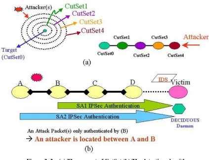
DECIDUOUS introduces the concept of CutSet. A CutSet is a group of routers which are
separated from the victim by the same hop count. With the concept of CutSet, DECIDUOUS
is able to transform the network topology into a linear topology [40]; thus, DECIDUOUS is
able to establish IPSec tunnels among different CutSets and work with IDS to identify attack
sources. Figures 3.3 (a) and 3.3(b) illustrate the CutSet and the detection algorithm for
DECIDUOUS to trace attacks.
As an intrusion detection system (IDS) is aware of attacks, it will signal the
DECIDUOUS daemon; and as a result, DECIDUOUS will set up IPSec tunnels from routers
tunnel. After DECIDUOUS has set up these tunnels, IDS will verify the attack again, based
on the authentication information provided by these tunnels, and then send the result to
DECIDUOUS which will decide whether the attack sources are within or beyond this CutSet.
If the attacker is within this CutSet, DECIDUOUS is able to discover the attack source by
examining the unique SPI. If the attack is beyond this CutSet, DECIDUOUS will destroy the
IPSec tunnels already built and set up other tunnels with other CutSets.
Figure 3. 3 – (a) The concept of CutSet (b) The detection algorithm.
The following are the algorithms (pseudo codes) for DECIDUOUS to discover attack
The pseudo codes for DECIDUOUS to set up SA and locate attack sources
Int Deciduous_Setup_SA {
/* Input: 1. IDS_ trigger&Signal. 2. Network topology
3.Transform_NetworkTopology_to_LinearCutSet (NetworkTopology); */
If (IDStrigger & Signal) {
while(CutSet!=NULL)
{ /* start from the nearest CutSet */ Establish_SA_FromCutSet2target( );
/* inform IDS with the SA information*/
SynchronizingWithIDS( );
Waitingfor_SignalFromIDS( );
If (Result ==Attack) Locate_AttackSource( );
}
}
return (DECIDUOUS_FINISH);
}
The pseudo codes for IDS to detect attacks and report the results for DECIDUOUS
Int IDS_Detection_attacks {
switch (DetectionStatus) {
case Without SASetup:
Signal_DECIDUOUS2Setup_SA( ); break;
case SAHasBeenSetup:
if (isAttackPacket){Signal_DECIDUOUS(“AttackPacket”, SPI=xxx”);} else {Signal_DECIDUOUS(“NoAttackPacket”);}
break; }
3.3.2
Challenges for DECIDUOUS module
Given the state of current network environment, the DECIDUOUS tracing scheme
faces two challenges. First, since DECIDUOUS is developed on top of the IPSec
infrastructure and utilizes the IPSec header information to locate attack sources, how to
obtain the IPSec security header for tracing attacks is a big issue. On the one hand, if the
attack can be detected in the network layer, the IDS can be integrated into the network
protocol stack and can obtain the security information directly, but on the other hand, if the
attack can only be detected above the network layer, the IDS is definitely unable to obtain the
original IPSec authentication header because the IPSec header information has been dropped
after the IPSec process is completed (for the incoming side) [28, 29]. Second, regarding
security concerns, different administration domains are not able to share local network
topologies with others. How to set up IPSec tunnels among inter-domain environments is
another challenge for the DECIDUOUS tracing model.
To overcome these challenges, the Packet Header Information List (PHIL) and
PHIL-API suite are proposed to allow the application-level IDS to access IPSec header information
[28]. Also the PHIL-switching technique is developed to extend the capability of
DECIDUOUS to support inter-domain tracing. The PHIL/APIs and the
PHIL-switching designs are presented in the following sections.
3.4
PHIL and PHIL-APIs
The techniques of PHIL and PHIL-APIs aim at solving the first challenge for the
DECIDUOUS tracing module. PHIL provides a data structure to store IPSec headers when
applications are able to receive both data and PHIL (IPSec headers). For sending data,
PHIL-APIs provide options for users to send both data packets and preferred SAs (authentication
algorithms and protocols) for IPSec to process these outgoing packets.
This technique not only solves the first problem of DECIDUOUS but also bridges the
big gap between IPSec and applications. As a result, any application which requires security
services can use IPSec to authenticate or encrypt data packets. Thus, the PHIL/PHIL-APIs
can reduce the duplication of security services at different layers, thereby simplifying the
design of applications.
3.4.1
Motivations
In current IPSec implementations, the important authentication header is discarded
when the IPSec process is finished; as a result, applications above IP layer are not able to
obtain the security information from the received data. Moreover, IPSec does not allow
applications to access a set of security attributes for sending packets. These issues, which are
major concerns for the DECIDUOUS tracing scheme, motivate us to study the glaring
deficiency of the IPSec protocol and propose a practical solution--PHIL/PHIL-APIs.
3.4.2
The design and Implementation of PHIL and PHIL-APIs
To bridge the gap between applications and IPSec, the Packet Header Information
List (PHIL) and PHIL-APIs are proposed to provide a socket mechanism (PHIL_APIs) for
applications to receive not only data but also IPSec headers (PHIL) from incoming packets.
This can be achieved by retaining the security headers while processing the incoming traffic
information can use PHIL-APIs (phil_enable( ) and phil_recvfrom( )) to retrieve the PHIL
information. For the outgoing side, more parameters as well as a socket mechanism
(phil_sendto( )) are added. In Figure 3.4, before the IPSec process discards the header
information, PHIL retains this important information from the incoming packets. On the
application level, the PHIL-API suite supports the user-level system calls to access the
incoming packets and the IPSec header information. For the outgoing packets, one can send a
query to the security association database (SAdb) to obtain available SAs. With the query
results and the PHIL-APIs, applications not only can send the data but can also request a
preferred SA for authenticating and/or encrypting outgoing data.
The capabilities of the PHIL-APIs are as follows:
For incoming traffic, the PHIL-APIs provide socket interfaces such that the
application developers are able to retrieve IPSec headers.
For outgoing traffic, the PHIL-APIs provide a functionality to interact with the
kernel's Security Association database (SAdb) and the Security policy database
(SPdb) to obtain available SAs. Thus, applications can use PHIL-APIs
((phil_sendto( )) to send out packets using these SAs.
The current implementation of PHIL/PHIL-APIs is in Linux kernel version 2.0.36 [43]
with FreeSwan.1.0 package [44]. The details of PHIL and the PHIL-API extension can be
IP layer T ransport layer
K ernel
SPdb
SA db
Phil_recvfrom ()
IP
packet PH IL T CP/UD P packet PH IL
D om ain
U ser D om ain
In-bound IPSEC traffic
Phil_sendto() T CP/UDP packet Specific SA Specific SA IP packet
Out-bound IPSEC traffic IPSEC Stack
In-bound Out-bound applications
Applications w/ specific SA
Security Policy AP I LD AP
Figure 3. 4 – PHIL and PHIL-API design concept
3.4.3
PHIL-API Suite
The PHIL-API suite can be categorized as follows: PHIL-APIs for receiving traffic,
PHIL-APIs for sending traffic, and the query functions.
I. There are three PHIL interfaces for users to receive data and PHIL:
a. int phil_enable( int sockfd, int mode )
A TCP [45] or UDP [46] socket opened with a socket system call should first be
enabled to receive the PHIL information along with the application data. Users can disable
the PHIL function as well.
Input: It takes the socket descriptor value (sockfd) and integer mode as input parameters
Returns: It returns a non-zero error value if the call failed, otherwise it returns a value
ZERO.
Description: phil_enable( ) prepares a socket to receive the PHIL information. The mode
parameter can either be EXHAUSTIVE or NON_EXHAUSTIVE. If the receive mode is
set to NON_EXHAUSTIVE, the PHIL information consists of only the SPI value
associated with each data segment. In the EXHAUSTIVE mode, the PHIL information
consists of the entire set of security parameters associated with the packet. This function
call must be used before any other extended API calls. After enabling a socket with
PHIL, an application can still use normal socket API calls to receive/send data. However,
PHIL-APIs must be used if someone wants to receive/send data and the PHIL.
b. int phil_accept(parameters to accept(), char *phil_buf,int phil_len)
Input: The parameters of the corresponding standard socket API call accept(), and the
buffer name (phil_buf) and its length (phil_len).
Returns: In addition to the return values of the corresponding normal API call accept(),
this call returns phil_buf, which is a character buffer that contains the PHIL information.
information about the peer party, which can be trusted based on the PHIL information. A
server can then decide whether it should accept the new request, based on some policies.
c. int phil_recvfrom(parameters to recvfrom(), char *phil_buf, int phil_len, int *dsegs)
Input: The parameters are the corresponding standard socket call--recvfrom(), the buffer
name (phil_buf), its length (phil_len), and integer pointer dsegs.
Returns: In addition to the return values of the corresponding normal system call
recvfrom(), this call also returns the phil_buf buffer, and the integer value dsegs is the
number of TCP data segments that constitute the total data bytes that were read from this
call.
Description: A phil recvfrom() call is used in place of a recvfrom() call to retrieve data
plus the PHIL. This call is used by both UDP and TCP applications.
II. Two PHIL-API function calls for sending data are presented.
a. int phil_bind(int sockfd, unsigned long *spi array, int size) int phi_unbind(int sockfd)
For the outgoing data, the phil_bind() can directly bind one or more SAs to a socket and
phil_unbind() can undo this binding.
Input: Socket descriptor value, the SPI array, and its size.
Description: The system call phil_bind() merely records a possible set of SPIs that could
be used by this socket. The specific values of SPIs for each sending process can be
different and should be specified at the time of phil_bind().
b. int phil_sendto(parameters to sendto(), long *spi_arr , int size)
Input: In addition to the corresponding normal API call sendto(), an SPI array and its
size are specified.
Returns: Number of bytes sent on success or a negative error value.
Description: The spi_arr array describes the preferred SPI values to be sent. If an
application is not aware of the possible SAs/SPIs, it can send a query to the SAdB to
obtain the SPI values through the query_spi() call. The value of the SPIs should be a
subset or equal to the SPI values that were bound to the socket using the phil_bind() call.
If only one spi among all the spi's was bound, the IPSec process will be applied to
outgoing packets. The spi field can be used to specify a SA or to choose a SA among
several possible SAs. Through this call, it is possible to multiplex the data from an
application over several SAs and provide different levels and features of security to
different data types. Here it is emphasized that the applications’ preference of sending its
data over a SA will be honored only if the applications conform to the SPDB. In case of
conflict between SPDB and an applications’ preference, the data will not be sent and the
III. Two query functions are implemented as follows:
a. int phil_ qspi (struct sockaddr* src, struct sockaddr * dst, char * buf, int size, int *num)
From phil_bind( ), an application might want to know the availability of SAs and their
SPI values before it sends data. The phil_qspi( ) satisfies such a request.
Input: Source and destination addresses and size of the buffer to hold the spi values.
Returns: ZERO on success and non-zero error value on failure. On success, this
function call returns the spi values in the buffer and the number of available spis in the
integer num.
Description: Because the SAs are simplex in nature, a query is sent to the SAdb to check
the availability of a specific SA. It is noticed that in the case of VPNs the source IP
address is most likely to be the security gateways of VPNs. The security protocol and the
spi value returned in the spi_struct will help the application to select a SA.
b. int phil_qsadb(unsigned long spi, struct sockaddr *dst, char * buf, int size)
This function is used to send a query to the SAdb for detailed information about the
SA that is indexed by the spi value, which is passed as a parameter.
Input: a selected spi, destination addresses, the pointer of the buffer, and size of the
buffer to hold the spi values.
Returns: ZERO on success and non-zero error value on failure. On success, the SA
Description: When an application sends data, it first sends a query to the SAdb to find
out whether a preferred SA exists. If the SA is in the SAdb, detailed SA information ---
protocols and algorithms -- will be put into the buffer and returned to this application.
With the support of the PHIL_API suite, developers can flexibly use phil_sendto()
with a preferred authentication/encryption protocol and security level to authenticate/encrypt
data , and use phil_recvfrom() to receive data and SA information.
3.4.4
The Evaluation of the PHIL implementation
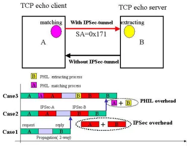
In this section, we present the evaluation of the overhead (delay) introduced by PHIL.
The major delay caused by PHIL is the PHIL extracting process from the incoming side and
the PHIL matching-and-replacing process on the outgoing side (see Figure 3.5).
The configuration for PHIL evaluation, as shown in Figure 3.5, includes two
machines: both are 450 MHz Pentium II personal computers equipped with 10 MB/sec
Ethernet cards. The echo client/server (TCP and UDP) program is developed to measure the
average delay. (It is noted that the delay is dominated by the IPSec process and the
request/reply processing time of CPU. The maximum delay could be actually caused by the
IPSec process and the request/reply process and not by the PHIL process. Thus measuring
the maximum value is meaningless for the PHIL evaluation. In this evaluation we just focus
on the measurement of the average delay and ignore the maximum delay.)
In each test, 100,000 packets are launched and the average time is calculated and
recorded. Various data sizes in 16, 32, 64, 128, 256, 512, 1,024 bytes are also tested to
depending upon the data size in each packet. Hence, the packet size is controlled (not to
exceed 1500 bytes) to avoid calculating the overhead twice.
Figure 3. 5– The configuration for PHIL evaluation and PHIL testing plan.
There are three test cases to evaluate the average delay:
Case 1: Using the Linux 2.0.36 kernel only.
Case 2: Using the Linux 2.0.36 kernel with the FreeS/wan IPSec package, no PHIL
process.
Case 3: Using the Linux 2.0.36 kernel with the FreeS/wan IPSec package and the
In each case, both protocols (ESP and AH) are tested. The results are shown in Table
3.1. From case 1 and case 2, the overhead caused by IPSec is calculated. From case2 and
case3, the overhead introduced by PHIL is computed. (Please see Figure 3.5.)
Table 3. 1: The results of evaluating IPSec/PHIL overhead
size(bytes) Case 1 Case 2 Case 3 PHIL overhead
(case3 – case2)
16 363 us ESP: 505 us ESP: 506 us ESP: 1 us
AH: 502 us AH: 502 us AH: 0 us
32 398 us ESP: 538 us ESP: 539 us ESP: 1 us
AH: 535 us AH: 536 us AH: 1 us
64 465 us ESP: 616 us ESP: 617 us ESP: 1 us
AH: 613 us AH: 613 us AH: 0 us
128 601 us ESP: 761 us ESP: 762 us ESP: 1 us
AH: 756 us AH: 757 us AH: 1 us
256 870 us ESP: 1050 us ESP: 1051 us ESP: 1 us
AH: 1045 us AH: 1046 us AH: 1 us
512 1410 us ESP: 1628 us ESP: 1630 us ESP: 2 us
AH: 1625 us AH: 1625 us AH: 0 us
1024 1510 us ESP: 1812us ESP: 1814us ESP: 2 us
AH: 1809 us AH: 1809 us AH: 0 us
We concluded from analyzing the results that no matter what the data size (less than
MTU) is, the average overhead introduced by PHIL is almost constant (1-2 microsecond)
because the extracting process and matching process are independent of the data size. (Please
note that the data size increase only causes the overhead of IPSec process to increase.) In our
test cases, we eliminated the effect of IPSec delay, which is not the overhead of PHIL
3.5
PHIL switching
The PHIL-switching technique is proposed to solve another problem posed by
DECIDUOUS: how to trace attacks across different domains. Instead of requesting other
domains to share their network topologies, one can utilize the PHIL-switching scheme to
correlate the security information among different administration domains. The premise of
the PHIL-switching scheme is that the relationships between SAs among peer domains are
maintained in the PHIL-switching table. If someone in an administration domain wants to
know the relationship of IPSec tunnels with another domain, he can send a query to the
PHIL-switching tables of these two domains to obtain the requested information. With the
PHIL-switching support, one can trace attack sources across different domains by sending
queries and analyzing the relationships among IPSec tunnels in different domains. For
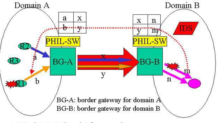
example, Figure 3.6 illustrates how DECIDUOUS works with the PHIL-switching scheme to
trace attacks across two administration domains. If the intrusion detection system (IDS)
within domain B detects an attack from the tunnel m, this result will be passed on to the
DECIDUOUS daemon of domain B. The DECIDUOUS daemon in domain B looks up its
PHIL-switching table and correlates the attack flow with the incoming tunnel y. Then the
DECIDUOUS daemon in domain B will inform the DECIDUOUS daemon of domain A
about the attack flow (tunnel y). The DECIDUOUS daemon of domain A, after receiving this
information, can simply look up its PHIL-switching table and correlate the attack with the
tunnel b. Ultimately DECIDUOUS is able to locate the attack source at R1. It is noted that
without the need to explore any network topology, the DECIDUOUS tracing scheme is able
to trace attack sources between these two domains by working with the PHIL-switching
Figure 3. 6 – DECIDUOUS tracing module with PHIL-switching support
3.5.1
The capabilities of the PHIL-switching
The capabilities of the PHIL-switching design are as follows:
For any incoming IPSec traffic, if it matches any entry in the PHIL-switching table, it
will be forwarded to a specific IPSec tunnel described in that entry.
If the incoming traffic is a non-IPSec packet, it may be processed as normal IP traffic,
i.e. the incoming traffic still can be forwarded but without being put into the IPSec
Traffic from different tunnels can be aggregated into one tunnel (IPSec traffic
aggregation).
The PHIL-switching provides filter functions to drop or switch packets regarding the
PHIL-switching policies.
The PHIL-switching provides interfaces for users to control the PHIL-switching table.
3.5.2
The design and implementation of the PHIL-switching
The PHIL-switching module includes two components:
• PHIL-switching controller: The PHIL-switching controller provides interfaces for users to add, delete or flush the PHIL-switching table. In the current PHIL-switching
implementation, the controller can provide two types of interfaces: the SNMP model and
the client/server model using UDP. In the SNMP model, one can control (read or write)
the PHIL-switching table through the SNMP mechanism. In the client/server model,
users can remotely control the PHIL-switching table through client-server
communication. Users can control the switching table in the following ways:
“Read“ the PHIL switching table,
“Add” one entry to the PHIL switching table,
“Delete” one entry from the PHIL switching table,
“Flush” the whole PHIL switching table.
• Switching entity: The switching entity provides switching functionality in the PHIL-switching mechanism. For any incoming packet with fields [SPI, security protocol,
daemon will look up the PHIL switching table, and then switch this packet into different
tunnel(s) using specified SPIs, which is defined in the PHIL switching table. If this
packet does not match any entry, it will be forwarded as normal traffic.
Figure 3. 7 – PHIL-switching function block.
The function blocks of the PHIL-switching are presented in Figure 3.7. The control
module provides interfaces-- the SNMP model or the client/server model--for users to control
or access the PHIL-switching table. The statistical module provides statistical information to
monitor the traffic through the PHIL-switching. The divert module provides a mechanism to
intercept desired packets from kernel domain. The switching module switches or drops the
packets, depending on the switching policies.
In the current stage, we implemented the PHIL-switching functionality on the user
domain because it is flexible: we can tune the PHIL-switching daemon without having to
packets from kernel domain to user domain. The Linux divert socket [47] has been designed
and implemented as part of a DARPA-funded network security project on ANR (Advanced
Network Research) of MCNC. It is open source and free downloadable.
3.5.3
The evaluation of PHIL-switching implementation
The configuration, shown in Figure 3.8, is set up to evaluate the overhead (delay)
caused by the PHIL-switching. There are three test cases in this evaluation. In case1, we set
up one-way IPSec tunnels between A and B and B and C. In case2, we used the divert socket
to obtain the incoming IP packet and then to re-inject the diverted IP packet into the kernel.
In case3, we used the divert socket to get the incoming IP packet and switched this packet by
using the phil_sendto( ) with specified SPI/SA to push the data back into the kernel. In each
case, we sent 10,000 packets to measure the overhead and recorded the average delay (total
time/10,000). (Since the maximum delay might be caused by IPSec process or divert socket
process, one snapshot of maximum measured value is meaningless to evaluate the maximum
delay of PHIL-switching. Thus we focus on only measuring the average delay and ignore the
measurement of maximum delay.) The overhead in the test cases includes the divert-socket
delay caused by divert intercepting process and PHIL switching process delay. We are more
interested in the delay of the PHIL-switching process because we can eliminate the overhead
of the divert process by implementing the PHIL-switching into the kernel.
The testing results are shown in Table 3.2. First, the results show that the overhead is
mainly caused by the divert process. Second, the results also show that the overhead of the
divert process and the PHIL-switching process is data-size dependent. If the data-size
the test case with 64 bytes is 1,382 microseconds. As data size increases to 1,024 bytes, the
overhead is 24,516 microseconds. It is noted that the overhead of divert-socket is worse than
the overhead of the PHIL-switching. The reason is that divert socket uses divert mechanism,
which is the lower priority, to re-inject packets. Therefore, this could potentially introduce
more delay as the packet size increases. Furthermore, the results also motivate us to
implement the switch module of the PHIL-switching daemon into the kernel to improve the
PHIL-switching performance.
Figure 3. 8 – The test cases for evaluating PHIL- switching
Table 3. 2: The test results of PHIL-switching.
Data size
Case1 (us)
Case2 (us)
Case3 (us)
Divert +divert re-inject overhead
Divert + PHILSW Overhead
16 777 1845 1860 1068 us 1083 us
64 979 2458 2361 1479 us 1382 us
256 1879 19407 13698 17528 us 11819 us
512 2860 39012 27679 36152 us 24819 us