ISSN(Online) : 2319-8753 ISSN (Print) : 2347-6710
I
nternational
J
ournal of
I
nnovative
R
esearch in
S
cience,
E
ngineering and
T
echnology
(An ISO 3297: 2007 Certified Organization) Vol. 5, Issue 3, March 2016
Design and Implementation of Distributed
Arithmetic Technique Based FIR Filter Using
Look up Table
M.Iruleswari1, M.Sheela Merlin2, A.Jeyapaul Murugan3
P.G. Student, Department of ECE, Dr.Sivanthi Aditanar College of Engineering, Tiruchendur, Tamil Nadu, India1,2
Assistant Professor, Department of ECE, Dr.Sivanthi Aditanar College of Engineering, Tiruchendur, Tamil Nadu,
India.3
ABSTRACT: Finite Impulse Response (FIR) filter is a basic part used in many Digital Signal Processing (DSP) application because of its linear phase, stability, low cost and simple structure. Designing a high-speed and hardware efficient FIR filter is a very difficult task as the complexity increases with the filter order. In most applications the higher order filters are required but the memory usage of filter increases exponentially with the order of the filter. Using multipliers occupy a large chip area and need more access time. Multiplier-less memory based techniques have gained popularity over past two or three decades due to their high throughput processing capability and reduced dynamic power consumption. This paper describes the design and implementation of highly efficient Look Up Table (LUT) based circuit for the implementation of FIR filter using Distributed arithmetic technique. It is a multiplier less FIR filter. The LUT can be subdivided into a number of LUT to reduce the memory usage of the LUT for higher order filter. Analysis on the performance of various filter orders are done using Xilinx 14.5 synthesis tool. The proposed design provides less latency, less memory usage and high throughput.
KEYWORDS: Finite Impulse Response (FIR), Distributed Arithmetic (DA), Look Up Table (LUT), Shift Accumulator, Multiply and Accumulate (MAC).
I. INTRODUCTION
Filter is a frequency selective network. It passes a band of frequencies while attenuating the others. Filters are classified as analog and digital depending on nature of inputs and outputs. Filters are further classified as finite impulse response and infinite impulse response filters depending on impulse response.
Digital filters are used extensively in all areas of electronic industry. This is because digital filters have the potential to attain much better signal to noise ratios than analog filters and at each intermediate stage the analog filter adds more noise to the signal, the digital filter performs noiseless mathematical operations at each intermediate step in the transform.
The digital filters have emerged as a strong option for removing noise, shaping spectrum, and minimizing inter-symbol interference in communication architectures. These filters have become popular because their precise reproducibility allows design engineers to achieve performance levels that are difficult to obtain with analog filters. Digital Filters can be constructed from 3 fundamental mathematical operations.
Addition (or Subtraction).
Multiplication (normally of a signal by a constant).
ISSN(Online) : 2319-8753 ISSN (Print) : 2347-6710
I
nternational
J
ournal of
I
nnovative
R
esearch in
S
cience,
E
ngineering and
T
echnology
(An ISO 3297: 2007 Certified Organization) Vol. 5, Issue 3, March 2016
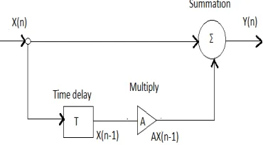
Fig. 1. Block diagram of a Simple Digital Filter
Fig. 1. shows a graphical means of describing a digital filter whereby the behavior of the filter is described by using the mathematical operations mentioned above.
The Impulse Response of a digital filter, h(n) is the response of the filter to an input consisting of the unit impulse function δ(n). If the impulse response of a system is known, it is possible to calculate the system response for any input sequence x(n). By definition, the unit impulse is applied to a system at sample index n=0. So, the impulse response is non-zero only for values of n greater than or equal to zero i.e h(n) is zero for n<0.
This impulse response is said to be causal otherwise the system would be producing a response before an input has been applied. It is known from the time-invariance property of a Linear Time Invariant System that the response of a system to a delayed unit impulse δ(n-k) will be a delayed version of the unit impulse, i.e h(n-k). It is also known from the linearity property that the response of a system to a weighted sum of inputs will be a weighted sum of responses of the system to each of the individual inputs. Therefore, the response of a system to an arbitrary input x(n) can be written as follows:
∑∞ x(k)
∞ h(n−k) ………… (1.1)
1.1 FIR FILTER
Finite Impulse Response (FIR) filters are one of two primary types of filters used in DSP, the other type being Infinite Impulse Response Filters (IIR) filters. The impulse response of an FIR filter is “finite" because there is no feedback in the filter. Compared to IIR filters, FIR filters offer the following advantages:
1. They can easily be designed to be "Linear Phase”. Linear-Phase filters delay the input signal, but don’t distort its phase.
2. They are simple to implement. On most DSP microprocessors, looping a single instruction can do the FIR calculation.
3. FIR filters are suited to multi-rate applications. i.e: reducing the sampling rate (decimation) or increasing the sampling rate (interpolation), or both Whether decimating or interpolating, the use of FIR filters allows some of the calculations to be omitted, thus providing an important computational efficiency. In contrast, if IIR filters are used, each output must be individually calculated, even if that output will be discarded (so the feedback will be incorporated into the filter).
4. FIR filters have desirable numeric properties. In practice, all Digital Signal Processing (DSP) filters must be implemented using "finite-precision" arithmetic, that is, a limited number of bits. The use of finite-precision arithmetic in IIR filters can cause significant problems due to the use of feedback, but FIR filters have no feedback, so they can usually be implemented using fewer bits, and the designer has fewer practical problems to solve related to non-ideal arithmetic.
ISSN(Online) : 2319-8753 ISSN (Print) : 2347-6710
I
nternational
J
ournal of
I
nnovative
R
esearch in
S
cience,
E
ngineering and
T
echnology
(An ISO 3297: 2007 Certified Organization) Vol. 5, Issue 3, March 2016
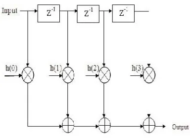
The direct form structure of FIR filter as shown in fig.2.
Fig. 2. Structure of FIR Filter
1.2 FIR FILTER LINEAR CONVOLUTION
An FIR filter is an example of a linear Time-Invariant (LTI) system and establish that the impulse response characterizes any LTI system, and the convolution of the input with the impulse response produces the output.
1.2.1 DERIVATION OF THE LINEAR CONVOLUTION Step 1:
For any signal is written as follows,
x(n) = ∑ x(l)δ(n−l) ………...(1.2) Where in the most general case the sum runs from -∞ to +∞.
Step 2:
The time invariance means that
δ(n−n0) = h(n−n0)
so that ∑x(l) δ(n−l) = ∑x(l) h(n−l) for any l Step 3:
Apply (1.2) on both sides to the system and use linearity to write
x(n) = ∑ x(l) δ(n−l)
∑ x(l)h(n−l) = y(n) ...………....(1.3)
For the case of an input signal having support over the entire axis n, the convolution sum formula becomes
y(n) = ∑∞ x(l)h(n−l)
∞ ……….(1.4)
II . DISTRIBUTED ARITHMETIC (DA) TECHNIQUE 2.1 DA TECHNIQUE
DA is basically (but not necessarily) a bit-serial computational operation that forms an inner (dot) product of a pair of vectors in a single direct step. The advantage of DA is its efficiency of mechanization. The modifications to increase the speed may be made by employing techniques such as bit pairing or partitioning the input words into the most significant half and least significant half, the least significant half of the most significant half, etc., thereby introducing parallelism in the computation.
A direct DA inner-product generation, consider the impulse response vector or coefficient h(k) and the input vector x(n-k) as,
ISSN(Online) : 2319-8753 ISSN (Print) : 2347-6710
I
nternational
J
ournal of
I
nnovative
R
esearch in
S
cience,
E
ngineering and
T
echnology
(An ISO 3297: 2007 Certified Organization) Vol. 5, Issue 3, March 2016
Y= ∑ ℎ( ) ( ) ………. (2.2)
Where s(k) = x(n-k),
L = word length.
S(k) may be expressed in two’s complement representation,
S(k) = -[ ( )] + ∑ [ ( )] 2 ……... (2.3)
Where [ ( )] denotes lth bit of s(k). substitute (3) in (2),
Y = - ∑ ℎ( )[ ( )] + ∑ ℎ( ) { ∑ [ ( )] 2 } ……... (2.4)
To convert the sum-of-products form of inner product of (2) into a distributed form, the order of summations over the indices k and l in (4) can be interchanged to have
Y = - ∑ ℎ( )[ ( )] + ∑ 2 { ∑ ℎ( )[ ( )] } ……... (2.5) The inner product can be computed as,
Y = ∑ 2 - ………... (2.6a)
Where = ∑ ℎ( )[ ( )] …………. (2.6b) The N-point bit sequence [s(k)] for {0 ≤ k ≤ N − 1} can either be 0 or 1, the partial sum Cfor 0 ≤ l ≤ L − 1 can have 2 possible values.
If all the 2 possible values of C are precomputed and stored in the LUT,the partial sums C can be read out from the LUT using thebit sequence {[ ( )] for 0 ≤ k ≤ N −1} as address bits forcomputing the inner product.
For simplicity, we may assume the signal samples to be unsigned words of size L, although the proposed algorithm can be used for two’s complement coding and offset binary coding .
We can always obtain unsigned input signal by adding fixed offset when the original input signal is signed. The inner product given by (6a) then can be expressed in a simpler form, i.e.,
Y = ∑ 2 ……. (2.7)
We can use (7) directly for straightforward DA-based implementation of FIR filter using the LUT containing 2
possible values of C .
For large values of N, however, the LUT size becomes too large, and the LUT access time also becomes large. The straightforward DA-based implementation is, therefore, not suitable for large filter orders.
When N is a composite number given by N = PM (P andM may be any two positive integers), one can map the index
k into (m + pM) for m = 0, 1, . . .,M −1 and p = 0, 1, . . . , P −1 to express (7) as
Y = ∑ 2 ( ∑ , ) …………... (2.8a)
Where , = sum of partial product of M samples.
, = ∑ ℎ( + )[ ( + )] … (2.8b)
Equation (8) can be written in terms of memory read operation as
Y = ∑ 2 [ ∑ ( , ) ] ….. (3.9)
Where F( , ) = , ,
, = { [ ( )] , [ (1 + )] , … … … . [ ( −1 + )] } .. (3.10)
The bit vector b, is used as address word for the LUT, and F(.) is the memory-read operation.
ISSN(Online) : 2319-8753 ISSN (Print) : 2347-6710
I
nternational
J
ournal of
I
nnovative
R
esearch in
S
cience,
E
ngineering and
T
echnology
(An ISO 3297: 2007 Certified Organization) Vol. 5, Issue 3, March 2016
The clock period in which the sign bits all simultaneously arrive is called the "sign-bit time." During the sign-bit time the control signal Ts = 1, otherwise Ts = 0.
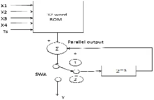
2.2 FIR REALIZATION USING DA
The DA of FIR filter consists of Look Up Table (LUT), Shift registers and scaling accumulator.
Fig. 4. FIR filter using look up table
By equation 5, each term inside the brackets indicates a binary AND operation involving a bit of the input variable and all the bits of the constant. The plus signs denote arithmetic addition operations. The exponential factors denote the scaled parts of the bracketed pairs to the total sum. Using this, a look-up table can be constructed that can be addressed by the same type of scaled bit of all the input variables and can access the sum of the terms within each pair of brackets. We can store these in a look-up table of 2 words addressed by N-bits. For example, if the number of inputs is 4, then the LUT will have 2 = 16 memory words.
Each product term consists of a variable (signal) and a constant (coefficient) both in fixed point binary format but not necessarily of the same word length; Rather than compute the product on a term by term basis, the partial products of all terms are computed simultaneously, and in the time it would take to compute a single partial product on bit by bit basis. These partial products are generally the filter coefficients. These partial product filter coefficients of all terms are cumulated on bit by bit basis .Finally all the cumulative partial products of each bit are added and the result is produced.
ISSN(Online) : 2319-8753 ISSN (Print) : 2347-6710
I
nternational
J
ournal of
I
nnovative
R
esearch in
S
cience,
E
ngineering and
T
echnology
(An ISO 3297: 2007 Certified Organization) Vol. 5, Issue 3, March 2016
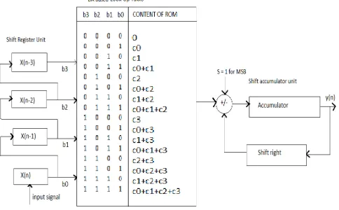
The conventional shift accumulator shown in Fig. 5 performs a shift right and add operation at every clock cycle and a subtraction in the last time slot called sign bit time. The input signal is given to the input shift register unit starts first with the least signifigant bits and corresponding output read out from the LUT is fed as input to the shift accumulator.
Fig. 6. Algorithm for right shift accumulator(RSA)
The computation performed by right shift accumulator(RSA) as shown in Fig. 6. Where the prerequisite being that the input signal given to the input shift register unit must start first with the most signifigant bits.
2.3 LOOK UP TABLE (LUT) PARTITIONING
The above technique holds good only when we go for lower order filters. For higher order filters, the size of the LUT also increases exponentially with the order of the filter. For a filter with N coefficients, the LUT have 2N values. This in turn reduces the performance.
Therefore, for higher order filters, LUT size to be reduced to reasonable levels. To reduce the size, the LUT can be subdivided into a number of LUTs, called LUT partitions. Each LUT partition operates on a different set of filter taps. The results obtained from the partitions are summed.
For 3rd order filter, the number of partition is required to 2. So that 2 LUT tables are used and each has 2 inputs. Memory location = no .of partition * 2
= 2*2
= 8 location Where n = number of inputs of LUT
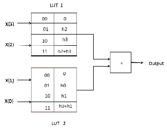
2.4 THIRD ORDER FIR FILTER WITH PARTITION METHOD
LUT is divided into LUT 1&LUT 2. Each LUT has 2 inputs and 4 memory location. It is shown in fig. 7. Input = 1101 means
First 2 bits are address bit of LUT 1, output becomes 01 = h0 and remaining 2 bits are address bit of LUT 2, output becomes 11 = h2 + h3.
Output = output of LUT1 + output of LUT 2 = h0+h2 + h3
ISSN(Online) : 2319-8753 ISSN (Print) : 2347-6710
I
nternational
J
ournal of
I
nnovative
R
esearch in
S
cience,
E
ngineering and
T
echnology
(An ISO 3297: 2007 Certified Organization) Vol. 5, Issue 3, March 2016
Fig. 7. Third order FIR filter with partition method
III. RESULT AND COMPARISON OF PERFORMANCE ANALYSIS
A novel LUT based Finite impulse response (FIR) filter using Distributed Arithmetic (DA) is designed to reduce the memory usage using Xilinx 14.5 software. The Distributed Arithmetic (DA) technique is further applied to 4-bit, 8-bit and 16-bit finite impulse response filter. The power consumption values for the various bits of FIR filter’s are compared with the Multiplier based technique to show better power savings
.
The proposed shift accumulator using right shift accumulator(RSA) was implemented for various input length using Xilinx vertex-6 FPGA device and a comparison of performance analysis is presented in table I.
The LUT partition based FIR filter using DA were implemented for various input length 4 bit,8 bit and 16 bit using Xilinx vertex-6 FPGA device and comparison of performance analysis is presented in table II and the memory usage of FIR filter is compared by using table III.
TABLE I
Comparison of performance analysis of LUT based FIR filter using DA
Input in Bits No. of Slices Maximum Frequency (MHz) Delay (ns)
4 26 293.140 1.726
8 45 152.673 3.513
16 69 145.797 3.604
TABLE II
Comparison of performance analysis of LUT partition based FIR filter using DA
Input in Bits
2 Partition 4 Partition
No. of Slices Maximum Frequency (MHz)
Delay (ns) No. of Slices Maximum Frequency (MHz)
Delay (ns)
4 28 356.861 1.482 - - -
8 51 214.561 2.435 53 197.906 2.526
ISSN(Online) : 2319-8753 ISSN (Print) : 2347-6710
I
nternational
J
ournal of
I
nnovative
R
esearch in
S
cience,
E
ngineering and
T
echnology
(An ISO 3297: 2007 Certified Organization) Vol. 5, Issue 3, March 2016
TABLE III
Comparison of memory usage of LUT based FIR filter using DA
Input in Bits No Partition 2 Partition 4 Partition
4 315120 KB 208752 KB -
8 238768 KB 209776 KB 208952 KB
16 243696 KB 210096KB 208880 KB
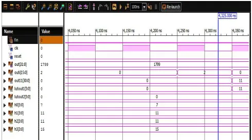
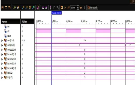
The waveform for the LUT based FIR filter using DA designs are shown in below. Fig.8 (a) shows the simulation result for 16 bit LUT based FIR filter using D,(b) shows the simulation result for LUT partitioning(2) based FIR filter using DA and (c) shows the simulation result for LUT partitioning(4) based FIR filter using DA.
Fig. 8 (a) Simulation result for LUT based FIR filter using DA
ISSN(Online) : 2319-8753 ISSN (Print) : 2347-6710
I
nternational
J
ournal of
I
nnovative
R
esearch in
S
cience,
E
ngineering and
T
echnology
(An ISO 3297: 2007 Certified Organization) Vol. 5, Issue 3, March 2016
Fig. 8 (c) Simulation result for LUT partitioning(4) based FIR filter using DA
IV. CONCLUSION
The simple approach proposed in this project is to reduce the memory usage of Look up table (LUT). The effective utilization of the LUT offers the great advantage in the reduction of the total memory usage. The Distributed Arithmetic (DA) technique is applied to the LUT Partition based Finite Impulse Response (FIR) filter using DA which yields maximum memory reduction compared to the LUT based Finite Impulse Response (FIR) filter using DA method. The proposed design is simulated using Xilinx 14.5 software. The simulation results clearly show that the proposed design has much less memory usage compared to the ordinary LUT based Finite Impulse Response (FIR) filter using DA technique. Using Xilinx 14.5, the memory usage of 4 bit FIR filter is about 215220KB and the memory usage of 8 bit FIR filter is about 238868KB and then the memory usage of 16 bit FIR filter is about 243796KB. After applying LUT partition technique the memory usage has reduced to 208852KB in 4 bit, 2209876KB in 8 bit and 2210196KB in 16 bit. The significant improvement in the memory usage is achieved because of the large LUT is decomposed into smaller LUT. Similarly, the memory usage values for the 4 bit, 8 bit and 16 bit LUT based FIR filter using DA is simulated using Xilinx vertex-6.
REFERENCES
[1] S. A. White (1989). “Applications of distributed arithmetic to digital signal processing: A tutorial review,” IEEE ASSP Mag., vol. 6, no. 3, pp. 4–19.
[2] G. Dempster and M. D. Macleod (1995).“Use of minimum-adder multiplier blocks in FIR digital filters,” IEEE Trans. Circuits Syst. II, Analog Digit. Signal Process., vol. 42, no. 9, pp. 569–577.
[3] D. J. Allred, H. Yoo, V. Krishnan, W. Huang, and D. V. Anderson (2005). “LMS adaptive filters using distributed arithmetic for high throughput,” IEEE Trans. Circuits Syst. I, Reg. Papers, vol. 52, no. 7, pp. 1327–1337.
[4] K.-H.Chen and T.-D. Chiueh (2006). “A low-power digit-based reconfigurable FIR filter,” IEEE Trans. Circuits Syst. II, Exp. Briefs, vol. 53, no. 8, pp. 617–621.
[5] P. K. Meher (2006). “Hardware-efficient systolization of DA-based calculation of finite digital convolution,” IEEE Trans. Circuits Syst. II, Exp. Briefs, vol. 53, no. 8, pp. 707–711.
[6] E. Ozalevli, W. Huang, P. E. Hasler, and D. V. Anderson (2008). “A reconfigurable mixed-signal VLSI implementation of distributed arithmetic used for finite-impulse response filtering,” IEEE Trans. Circuits Syst. I, Reg. Papers, vol. 55, no. 2, pp. 510–521.
[7] P. K. Meher, S. Chandrasekaran, and A. Amira (2008). “FPGA realization of FIR filters by efficient and flexible systolization using distributed arithmetic,” IEEE Trans. Signal Process., vol. 56, no. 7, pp. 3009–3017.
[8] P. K. Meher and S. Y. Park (2011). “High-throughput pipelined realization of adaptive FIR filter based on distributed arithmetic,” in Proc. IEEE/IFIP 19th Int. Conf. VLSI-SOC, pp. 428–433.
[9] L. Ming and Y. Chao (2012).“The multiplexed structure of multi-channel FIR filter and its resources evaluation,” in Proc. Int. Conf. CDCIEM, pp. 764–768.
[10] Hatai, I. Chakrabarti, and S. Banerjee (2013). “Reconfigurable architecture of a RRC FIR interpolator for multi-standard digital up converter,” in Proc. IEEE 27th IPDPSW, pp. 247–251.