Implementation of Low Density Parity Check
Code Decoder on FPGA
Pramodkumar B. Wavdhane1, A. B. Wagh2
PG Student [VLSI], Dept. of ENTC, Smt. Kashibai Nawale College of Engineering, Pune, Maharashtra, India1
Assistant Professor, Dept. of ENTC, Smt. Kashibai Nawale College of Engineering, Pune, Maharashtra, India2
ABSTRACT:Hard decision algorithms are widely used for error correcting performance but as the technology scales down we need advanced codes to correct the errors with less number of parity data ratios. Nowadays the Low Density Parity Check (LDPC)code is used widely because it has good error correcting performance than other soft decision algorithms. For this LDPC code various decoders are used like Belief Propagation (BP)and the approximations of BP like Min Sum algorithm, but this algorithm suffers from the error floor problem. which caused because of the unwanted topological structure called trapping sets. This problem can be solved with the Finite Alphabet Iterative Decoding algorithm which performs well in the error floor region. Again this algorithm gives same throughput as that of the BP and min sum algorithm with lesser area.
KEYWORDS: Low Density Parity Check code, Parity Check Matrix,Belief Propagation, Min Sum, Error Floor.
I.INTRODUCTION
The codes can be defined in terms of the non-systematic low density parity check matrix, such kind of representation can be known asLow Density Parity Check (LDPC) codes. Generally the LDPC codes can be used for many channels like the Binary Symmetric Channel (BSC) and Additive White Gaussian Noise (AWGN) channels. They are again good for the memory less channel. The LDPC codes can overcome the Shannon limit,when decoded by the Belief Propagation (BP)or its approximations. Shannon limit is the channel capacity i.e. the maximum information transfer rate of the channel in the presence of noise. If the bit rate exceeds to particular value then it cannot correct the bit but the LDPC codes can correct the bits from the Shannon region[1].
The LDPC codes can be given in the form of Parity Check Matrix (H). As LDPC code has large number of the parity check matrix, so it gives good decoding performance. The increase in the length of the code increases the decoding complexity. The LDPC code is kind of the block codes. The H can be given in the graphical form known as the tanner graph. This representation makes the LDPC codes looks easy in the form of decoding performance. It’s a bipartite graph having variable node at one side and check nodes on other side and the nodes connected with the edges. The transmitted block length is N and the source block length is m so the parity check bits can be given as n-m. The parity check matrix is a rectangular matrix of m*n as the message bits gives the check nodes and the parity check bits gives the variable nodes. A check node and the variable node connected when there is nonzero entry in the H. The decoding procedure can be carried by passing the messages on the edges, when the desired value is found the decoder gives the output [1]-[2].
As the LDPC codes used in many applications due to their different useful characteristics but the error floor remains open problem,As the applications like data storage system and the optical communications require very low error rate. In such cases the error floor becomes very critical point. There are many ways are developed to solve the error floor problem like the scheduling of the decoders or the algorithm uses average of the decoding iterations. We can improve the error floor problem by decoder modifications or the post processing of the data.The error floor is the abrupt change in slope of the performance curve of code. It is observed that the algorithm or the channel decoding fails due to the some topological structure. The failure in iterative decoder is due to the combinational object known as the trapping sets [3].
Such kind of the sets arises in the tanner graph due to which the error floor problem induced. In the set {v1, v2, v3, v4, v5} the smallest inducing set might be any variable node which belongs to the above set [4].
Fig.1 Trapping Set
II.RELATED WORK
The Belief Propagation(BP) based algorithm can efficiently decode theLDPC codes.It uses graphical modelfor the decoding purpose so it has low complexity architecture. It works well for LDPC codes nearly it approaches to Shannon limit. Because of this advantage this decoder used in many applications. But in low noise region this codes suffers the problem of error floor. The BP algorithm calculates the marginal of the function with the help of the graphical model known as tanner graph. And has its roots in baysian interference problems. This algorithm provides exact marginal on the loopy graphs. Due to the restrictions in the graphical model topology the exact interference in the baysian belief network becomes hard. The algorithm which uses the loopy structure can perform better than the algorithms which do not uses the loopy structure in the graphs. As that of the previous decoder this decoder perform the iterative method for decoding purpose .Hence we have simple decoders on one site that is gallgers decoders and the decoders on the other site that is BP. The gap between this varies according to the complexity of the decoder. This again depends upon the length of the codes[5].
The LDPC decoder performs very well when decoded by the BP algorithm, but it includes complex computation which makes the decoder very complex. If the length of the code is small it performs well but as the length increases the decoding makes quite hard. To overcome this problem the approximations of the BP are to be used i.e. Min Sum decoder. The improvements mainly includes in the Check Node Unit. As the min sum decoder is approximation of the BP it works same as that of the BP algorithm i.e message passing on the edges of the tanner graph [6].
III.SYSTEM ARCHITECTURE
The messages are nothing but the finite alphabets in the FAID, As the FAID don’t work as that of the Belief propagation givingthe values in the log likelihood probabilities. These functions are predefined maps designed using the knowledge of potentially harmful sub graphs that could be present in a given code, so these decoders works well than the BP in the error floor region. On certain column-weight-threethereexist 3-bit precision FAIDs that surpass the BP decoder in the error floor. FAIDs are able to performbetter at much lower complexity. As the FAID is message passing algorithm as that of the traditional algorithm, the important blocks in the algorithm are check node unit and variable node unit. The value from the variable node unit then passed to the check node unit.In this way the messages passed on check to variable nodes and variable to check nodes and permutations carried out and the data decoded [2]-[7].
1. VNU ARCHITECTURE
TheVariable Node Unit (VNU) architecture for decoding of low density parity check code decoder is as shown in the
mapping Conv.
Conv.
Conv. y
m0
m1
m2
Hard decision
Fig.2 Variable Node Unit
In fig. 2 the messagesmo to m2andchannel input y given to the variable node unit. The channel inputs are nothing but
the predefined Boolean maps. The data get calculated and passed to the check node unit. The data get calculated as per the following equation.
(1)
Where b is sign bit and moto mdv-1are the messages. The messages get calculated and the messages further passed to the check node unit [2].
2. CNU ARCHITECTURE
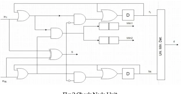
The Check Node Unit (VNU) architecture for decoding of low density parity check code decoder is as shown in the
following figure.
Fig.3 Check Node Unit
Fig. 3 gives the architecture of the check node unit, in which the in1 to indc are the inputs given to the CNU.The
messages start with MSB and end up with the LSB the least significant bit is the sign bit. The CNU equation is given as follows
(2)
IV.SYSTEM FLOW
In the flow chart how the FAID decoding process can be carried is explained. The channel information is given for further processing it is nothing but the predefined Boolean maps along with the message bits. This data first provided to the variable node unit. After the data converted to the serial form and passed to the calculation block. The calculated data further provided to the check node unit in which the min value and the sign of the data get calculated and again the reverse calculation is done. The serial data get converted to the parallel form and passed to the variable node unit. This procedure continues until we get the desired value.
V. RESULT AND DISCUSSION
The implemented system is compared with the various previous methods in terms of area, memory and delay. The area is considered in terms of utilization of LUTs, gate count and slices. The delay is compared on the basis of gate delay or path delay. It is observed that the system requires lesser area than the other decoders in terms of LUTs, gate count and slices.
Table.1 Logic Utilization Summary of FAID
Logic utilization Used Available Utilization
Number of slice Flip Flops 385 7168 5%
Number of 4 input LUTs 249 7168 3%
Logic Distribution
Number of occupied slices 311 3584 8%
Number of slices containing related logic 311 311 100%
Total number of 4 input LUTs 249 7168 3%
Number of bonded IOBs 137 141 97%
IOB flip flops 99
Number of GCLKS 1 8 12%
VI.CONCLUSION
In this paper we have studied low density parity check codes. Its Shannonlimit approaching performance. Various decoders like BPand the Min Sum decoders used to decode the Low Density Parity Check codes, But the BP based decoder causes the error floor problem at very low error rate. The FiniteAlphabet Iterative Decoder performs better than that of the BP decoder. It takes less area and gives same performance as that of the other decoders. The system is implemented in Verilog HDL, simulated in Modelsim 6.4c and synthesized using Xilinx ISE 14.2. The hardware used for implementation is Virtex-5 FPGA.
REFERENCES
[1] M. Davey and D. J. MacKay, “Low density parity check codes over GF (q),” IEEE Commun. Lett., vol. 2, pp. 165–167, Jun. 1998.
[2] Fang Cai,Xinmiao Zhang, David Declercq, Shiva Kumar Planjery, and Bane Vasić , “Finite Alphabet Iterative Decoders for LDPC Codes: Optimization, Architecture and Analysis”, IEEE trans. on circuits and systems—I: regular papers, vol. 61, no. 5, pp.1366-1375, may 2014. [3] T. Richardson, “Error floors of LDPC codes,” in Proc. 41st Annu. Allerton Conf. Commun. Control Comut., 2003.
[4] B. Vasic, S. K. Chilappagari, D.V. Nguyen, and S.K. Planjery, “Trapping set ontology,” in Proc. 47th Annu. Allerton Conf. Commun., Control,Comput., Sep. 2009.
[5] S. K. Planjeryet al., “Iterative decoding beyond belief propagation,” in Proc. Info. Theory Appl. Workshop, Feb. 2010.
[6] FabiánAngarita, Javier Valls, Member, IEEE, VicençAlmenar, and Vicente Torres,” Reduced-Complexity Min-Sum Algorithm for Decoding LDPC Codes With Low Error-Floor,” IEEE Trans On Circuits And Systems—I: Regular Papers, vol. 61 no. 7, pp. 2150-2158, July 2014. [7] S. K. Planjery, D. Declercq, L. Danjean, and B. Vasic, “Finite alphabet iterative decoders, Part I: Decoding beyond belief propagation on the