Scholarship@Western
Scholarship@Western
Electronic Thesis and Dissertation Repository
4-23-2012 12:00 AM
Enabling Techniques Design for QoS Provision in Wireless
Enabling Techniques Design for QoS Provision in Wireless
Communications
Communications
Penghui Mi
The University of Western Ontario
Supervisor Dr. Xianbin Wang
The University of Western Ontario
Graduate Program in Electrical and Computer Engineering
A thesis submitted in partial fulfillment of the requirements for the degree in Master of Engineering Science
© Penghui Mi 2012
Follow this and additional works at: https://ir.lib.uwo.ca/etd
Part of the Systems and Communications Commons
Recommended Citation Recommended Citation
Mi, Penghui, "Enabling Techniques Design for QoS Provision in Wireless Communications" (2012). Electronic Thesis and Dissertation Repository. 436.
https://ir.lib.uwo.ca/etd/436
This Dissertation/Thesis is brought to you for free and open access by Scholarship@Western. It has been accepted for inclusion in Electronic Thesis and Dissertation Repository by an authorized administrator of
in Wireless Communications
(Spine title: QoS Guarantees in Modern Communication Systems)
(Thesis format: Monograph)
by
Penghui Mi
Graduate Program in
Engineering Science
Department of Electrical and Computer Engineering
A thesis submitted in partial fulfillment of the requirements for the degree of
Master of Engineering Science
The School of Graduate and Postdoctoral Studies The University of Western Ontario
London, Ontario, Canada
c
SCHOOL OF GRADUATE AND POSTDOCTORAL STUDIES
CERTIFICATE OF EXAMINATION
Chief Advisor: Examining Board:
Dr. Xianbin Wang Dr. Evgueni Bordatchev
Advisory Committee: Dr. Jagath Samarabandu
Dr. Weiming Shen
The thesis by
Penghui Mi
entitled:
Enabling Techniques Design for QoS Provision in Wireless Communications
is accepted in partial fulfillment of the
requirements for the degree of Master of Engineering Science
Date:
Chair of Examining Board Dr. R. K. Rao
Guaranteeing Quality of Service (QoS) has become a recognized feature in the design of
wireless communications. In this thesis, the problem of QoS provision is addressed from
different prospectives in several modern communication systems.
In the first part of the thesis, a wireless communication system with the base station
(BS) associated by multiple subscribers (SS) is considered, where different subscribers
re-quire different QoS. Using the cross-layer approach, the conventional single queue finite
state Markov chain system model is extended to multiple queues’ scenario by
combin-ing the MAC layer queue status with the physical layer channel states, modeled by
fi-nite state Markov channel (FSMC). To provide the diverse QoS to different subscribers,
a priority-based rate allocation (PRA) algorithm is proposed to allocate the physical layer
transmission rate to the multiple medium access control (MAC) layer queues, where diff
er-ent queues are assigned with different priorities, leading to their different QoS performance
and thus, the diverse QoS are guaranteed.
Then, the subcarrier allocation in multi-user OFDM (MU-OFDM) systems is stuied,
constrained by the MAC layer diverse QoS requirements. A two-step cross-layer dynamic
subcarrier allocation algorithm is proposed where the MAC layer queue status is firstly
modeled by a finite state Markov chain, using which MAC layer diverse QoS constraints
are transformed to the corresponding minimum physical layer data rate of each user. Then,
with the purpose of maximizing the system capacity, the physical layer OFDM subcarriers
are allocated to the multiple users to satisfy their minimum data rate requirements, which
is derived by the MAC layer queue status model.
Finally, the problem of channel assignment in IEEE 802.11 wireless local area
net-works (WLAN) is investigated, oriented by users’ QoS requirements. The number of users
in the IEEE 802.11 channels is first determined through the number of different channel
im-pulse responses (CIR) estimated at physical layer. This information is involved thereafter
in the proposed channel assignment algorithm, which aims at maximum system
through-put, where we explore the partially overlapped IEEE 802.11 channels to provide additional
frequency resources. Moreover, the users’ QoS requirements are set to trigger the channel
assignment process, such that the system can constantly maintain the required QoS.
First, and foremost, I would like to express my genuine and sincere gratitude to my
super-visor, Prof. Xianbin Wang for his guidance, support and encouragement in the developing
of my research. It was him who brought me into the filed of wireless communications and
without his vision, deep insight, valuable advices and continuous supports, this work would
never have been possible. It is an great honor for me to join this research group and work
with him. This journey is proven to be enjoyable and rewarding.
Sincere thanks to Dr. Evgueni Bordatchev, Dr. Jagath Samarabandu and Dr.
Weim-ing Shen for joinWeim-ing in my committee as well as their valuable time and constructive
sug-gestions.
I would also like to thank the faculties, stuffs and students I met in The University of
Western Ontario, who have helped me directly or indirectly in completing my studies.
As always, I deeply own my thanks to my parents and my sister for their love and
support throughout this degree and my life.
Certificate of Examination . . . ii
Abstract . . . iii
Acknowledgements . . . v
List of tables . . . x
List of figures . . . xi
Acronyms . . . xiii
1 Introduction . . . 1
1.1 Research Motivations . . . 1
1.2 Research Objectives . . . 2
1.3 Thesis Contributions . . . 3
1.4 Thesis Organization . . . 4
2 Basic Concepts Preview . . . 6
2.1 Discrete-time Markov Chains . . . 6
2.1.1 Definition . . . 6
2.1.2 State Transition Probability Formulation . . . 6
2.1.3 State Probability Formulation . . . 8
2.1.4 Steady-state Behavior . . . 9
2.1.4.1 Ergodic Markov chain . . . 9
2.1.4.2 Stationary distribution of Markov chain . . . 9
2.2 Queueing System . . . 10
2.2.1 Input Process . . . 10
2.2.2 System Structure . . . 11
2.2.3 Output Process . . . 12
2.2.4 Kendall Notation . . . 13
2.3 OFDM System . . . 13
2.3.1 Concept of OFDM . . . 13
2.3.2 OFDM Transmitter . . . 15
2.3.3 OFDM Receiver . . . 17
2.3.4 Advantages and Disadvantages of OFDM systems . . . 18
2.4 IEEE 802.11 WLAN . . . 20
2.4.1 Overview of WLAN . . . 20
2.4.2 The PHY and MAC of WLAN . . . 21
2.4.2.1 The physical layer . . . 21
2.4.2.2 The media access control layer . . . 21
2.5 Summary . . . 24
3 Modeling of Wireless Communications for Diverse QoS Provision . . . 25
3.1 Introduction . . . 25
3.2 System Model . . . 27
3.2.1 System Description . . . 27
3.2.2 Adaptive Modulation and Coding . . . 30
3.2.3 Finite State Markov Channel . . . 32
3.2.3.1 Channel partitionings . . . 33
3.2.3.2 Channel state transition probabilities . . . 35
3.3 Proposed Multiple Queue Finite State Markov Chain System Model . . . . 37
3.3.1 Queue Behavior Modeling . . . 37
3.3.2 Priority-Based Rate Allocation . . . 38
3.3.3 System Modeling Using Finite State Markov Chain . . . 40
3.3.3.1 Derivation of state transition matrix . . . 40
3.3.3.2 Stationary distribution of Markov chain . . . 41
3.4 System QoS Performance . . . 41
3.4.1 Packet Loss Rate . . . 42
3.4.2 Average System Delay . . . 43
3.5 Simulations . . . 44
3.5.1 Parameter Setting . . . 44
3.5.2 Simulation Results . . . 44
3.6 Summary . . . 48
4 QoS Constrained Subcarrier Allocation in MU-OFDM system . . . 49
4.1 Introduction . . . 49
4.2 System Model . . . 51
4.3 Problem Formulation . . . 52
4.4 Proposed Cross-Layer Dynamic Subcarrier Allocation . . . 54
4.4.1 MAC Layer Queue Status Model . . . 54
4.4.1.1 Queuing model using finite state Markov Chain . . . 54
4.4.1.2 QoS performance analysis . . . 55
4.4.2 Dynamic Subcarrier Allocation at Physical Layer . . . 56
4.5 Simulations . . . 59
4.5.1 Parameter Setting . . . 59
4.5.2 MAC Layer Queue Performance . . . 59
4.5.3 Physical Layer Subcarrier Allocation Performance . . . 61
4.6 Summary . . . 63
5 QoS Oriented Channel Assignment in IEEE 802.11 WLANs . . . 64
5.1 Introduction . . . 64
5.2 System Model . . . 67
5.3 CIR-Based User Number Estimation . . . 68
5.3.1 Physical Layer Model . . . 68
5.3.2 LS Channel Estimation . . . 69
5.3.3 Mitigation of CIR Estimation Noise . . . 70
5.3.4 Hypothesis Testing for CIR Differentiation . . . 72
5.3.5 Adaptive CIR Determination Threshold . . . 73
5.3.6 Details of the CIR-Based Estimation Algorithm . . . 74
5.4 Channel Assignment Exploiting IEEE 802.11 Partially Overlapped Channels 76 5.4.1 Interference Analysis of Partially Overlapped Channels . . . 76
5.4.2 Problem Formulation . . . 78
5.4.3 Interference Factor (I-factor) Calculation . . . 80
5.4.4 Implementation of the Proposed Channel Assignment Algorithm . . 81
5.5 Simulations . . . 82
5.5.1 Parameter Setting . . . 82
5.5.2 Adaptive Noise Elimination and CIR Determination Thresholds . . 82
5.5.3 Accuracy Analysis of CIR-based User Number Estimation . . . 84
5.5.4 IEEE 802.11 WLAN System Performance Improvement . . . 85
5.6 Summary . . . 87
6 Conclusion and Future Work . . . 88
6.1 Conclusion . . . 88
6.2 Future Work . . . 89
References . . . 91
Curriculum Vitae . . . 98
3.1 Transmission Modes with UncodedMn -QAM Modulation . . . 31
3.2 Transmission Modes with Conventionally Coded Modulation . . . 31
5.1 Simulation Parameters for User Number Estimation . . . 82
5.2 IEEE 802.11 System Parameters . . . 83
2.1 State transition diagram of discrete-time Markov chain. . . 7
2.2 Periodic Markov chain. . . 9
2.3 Schematic diagram of a queueing system. . . 10
2.4 System structure of a queueing system: parallel servers. . . 11
2.5 System structure of a queueing system: serial servers. . . 12
2.6 The structure of OFDM symbol with cyclic prefix. . . 16
2.7 Block diagram of OFDM transmitter. . . 16
2.8 Constellation diagram for rectangular 16-QAM. . . 17
2.9 Block diagram of OFDM receiver. . . 18
2.10 Elimination of ISI through cyclic prefix. . . 18
2.11 Bandwidth utilization comparison between the OFDM system and the con-ventional FDM system [7]. . . 19
2.12 IEEE 802.11 MAC architecture. . . 22
2.13 CSMA/CA basic access mechanism. . . 22
2.14 CSMA/CA CTS/RTS mechanism. . . 23
3.1 Wireless communication system diagram with a base station associated by multiple subscribers . . . 28
3.2 Wireless link from the base station (BS) to a subscriber (SS) . . . 28
3.3 Physical layer frame structure . . . 29
3.4 Channel partitioning in FSMC [38] . . . 33
3.5 N+1 finite state Markov channel . . . 35
3.6 Packet loss rate under different pre-defined packet error rates. . . 45
3.7 Average system delay under different pre-defined packet error rates. . . 46
3.8 Packet loss rate under different traffic loads. . . 46
3.9 Average system delay under different traffics loads. . . 47
4.1 Multiuser OFDM system. . . 51
4.2 Packet loss rate under different physical layer data rates. . . 60
4.3 MAC layer average queue size under different physical layer data rates. . . 61
4.4 Normalized ergodic sum capacity distribution among users. . . 62
5.1 Typical infrastructure-based IEEE 802.11 WLAN with AP transmission range overlap. . . 67
5.2 Threshold to eliminate the environment noise. . . 71
5.3 IEEE 802.11 channels in the 2.4GHz ISM band [68]. . . 76
5.4 Transmit spectrum mask for IEEE 802.11 OFDM modulation. . . 77
5.5 Theoretical I-factor on 2.4GHz 802.11 channels with OFDM modulation. . 80
5.6 Noise elimination threshold under different path number and SNR combi-nations. . . 83
5.7 CIR determination threshold under different path number and SNR combi-nations. . . 84
5.8 CDF of the estimation errors under different SNR situations. . . 85
5.9 MAC layer packet drop rate under different packet arrival rates with diff er-ent AP numbers. . . 86
5.10 Average system throughput under different packet arrival rates with diff er-ent AP numbers. . . 86
ACK Acknowledgement
ADC Analog-to-Digital Converter
AWGN Additive White Gaussian Noise
A/D Analog-to-Digital
AMC Adaptive Modulation and Coding
AP Acess Point
AR-1 Autoregressive model of order 1
BER Bit-Error-Rate
BS Base Station
CDF Cumulative Distribution Function
CFO Carrier Frequency Offset
CIR Channel Impulse Response
CP Cyclic Prefix
CSI Channel State Information
CSMA/CA Carrier Sense Multiple Access with Collision Avoidance
CTS Clear To Send
DAC Digital-to-Analog Converter
D/A Digital-to-Analog
DCF Distributed Coordination Function
DIFS Distributed Interframe Space
DSSS Direct Sequence Spread Spectrum
ETSI European Telecommunications Standards Institute
EUN Equivalent User Number
FCFS First-Come-First-Served
FDM Frequency Division Multiplexing
FEC Forward Error Coding
FFT Fast Fourier transform
FHSS Frequency Hopping Spread Spectrum
FIFO First-In-First-Out
FSMC Finite State Markov Channel
HiperLAN High performance radio Local Area Network
IDFT Inverse Discrete Fourier Transform
IFFT Inverse Fast Fourier Transform
IR Infrared Light
ISI Intersymbol Interference
ISM Industrial, Scientific, and Medical
LCFS Last-Come-First-Served
LCR Level Crossing Rate
LS Least Square
MAC Medium Access Control
MSE Mean Squared Error
MIMO Multiple-Input Multiple-Output
MU-OFDM Multi-user OFDM
NAV Network Allocation Vector
OFDM Orthogonal Frequency Division Multiplexing
PAPR Peak-to-Average Power Ratio
PDF Probability Density Function
PER Packet Error Rate
PRA Priority-based Rate Allocation
PCF Point Coordination Function
PHY Physical
PLCP Physical Layer Convergence Procedure
PMD Physical Medium Dependent
P/S Parallel-to-Serial
QAM Quadrature Amplitude Modulation
QoS Quality of Service
RS Random Selection
RTS Request to Send
SIFS Short Inteframe Space
SNR Signal-to-Noise Ratio
S/P Serial-to-Parallel
SS Subscriber
STA Station
UNII Unlicensed National Information Infrastructure
Wi-Fi Wireless Fidelity
WLAN Wireless Local Area Network
Chapter 1
Introduction
1.1
Research Motivations
Quality of Service (QoS) guarantees is becoming increasingly important nowadays since
the wireless systems is moving toward the ubiquitous way with high quality wireless
ser-vices requirements. Supporting various applications, such as file, voice, multimedia and
so forth, is one of the critical roles for wireless communications and obviously, different
applications require different QoS. Considering the scarcity of the wireless communication
resources, i.e. the limited bandwidth and power, it is a great challenge to fulfill the QoS
guarantee requirements in wireless communications and lots of issues left unsolved in this
area.
In general, wireless communications include concepts and technologies for
innova-tions in architectures, spectrum allocation, and utilization, in radio communicainnova-tions,
net-works, and services and applications [1]. Therefore, the issue of QoS provision in wireless
communications could be addressed from the above aspects.
In this thesis, in order to provide QoS in modern wireless communication systems,
we focus on the provision of QoS from different aspects. Firstly, a new system architecture
with multiple queues at MAC layer is modeled by a finite state Markov chain to provide
diverse QoS in wireless communications. Then, we consider the subcarrier allocation in
layer. Moreover, we also research on the widely investigated IEEE 802.11 WLANs and
discuss the channel assignment in this system, oriented by users’ QoS requirements.
1.2
Research Objectives
Various algorithms have been proposed in the literature to discuss the QoS guarantee
prob-lems in different wireless communication systems. The objective of this thesis is to resolve
the problem of QoS provision from different prospectives regarding to different
communi-cation systems.
First, since different applications call for different QoS support, providing diverse
QoS for different users is essential and imperative in modern wireless communications.
With regard to this, the first research objective of this thesis is to extend the conventional
single queue finite state Markov chain system model to multiple queues’ scenario, such that
different users can be provided with different QoS thanks to the diversity introduced by the
multiple queues.
Then, most of the existing resource allocation algorithms in MU-OFDM systems are
only based on the physical layer information for best-effort performance provision, without
any QoS guarantee. Therefore, constrained by users’ QoS requirements, we aim at
devel-oping a cross-layer subcarrier allocation algorithm which combines the QoS constraints
together with the physical layer channel condition to allocate the subcarrier in a manner
that users’ QoS requirements can be satisfied.
Lastly, we address the issue of channel assignment in IEEE 802.11 WLANs for the
sake of solving the problem of frequency scarcity and users’ QoS maintainenace. In this
thesis, we estimate the number of users at physical layer to reduce the latency and when
additional frequency resources and the system QoS performance is the trigger of the
chan-nel assignment process.
1.3
Thesis Contributions
The main contributions of this thesis can be summarized as:
• We extend the conventional single queue finite state Markov chain system model to
multiple queues’ scenario and a priority-based rate allocation algorithm is proposed
to explore the diversity of the multiple queues and thus, provide the diverse QoS.
• A cross-layer subcarrier allocation algorithm is proposed in MU-OFDM system, with
the diverse QoS constraints at MAC layer. Finite state Markov chain is employed to
model the queue status, using which the MAC layer diverse QoS constraints are
transformed to the minimum physical layer data rate requirement of each user, which
is satisfied through the proposed subcarrier allocation algorithm at physical layer.
• We propose a CIR-based user number estimation algorithm to determine the number
of users in IEEE 802.11 channels. The CIR estimation noise is mitigated through
an adaptive noise elimination thresholds and when differentiating the CIRs,
adap-tive CIR determination threshold are introduced to further improve the estimation
accuracy.
• A QoS-oriented channel assignment algorithm in IEEE 802.11 WLANs is proposed,
where the partially overlapped IEEE 802.11 channels are utilized to solve the
prob-lem of frequency scarcity. Moreover, interferences between the partially overlapped
1.4
Thesis Organization
The rest of the thesis is organized as follows:
Chapter 2 provides the previews of some basic concepts. The discrete-time Markov
chain is firstly introduced from a mathematical point of view, followed by the details of
queueing system. We then review the OFDM system and the IEEE 802.11 WLAN.
Chapter 3 describes the proposed finite state Markov chain system model with
multi-ple MAC layer queues, where we first briefly introduce the research background and some
of the existing related works, followed by the introduction of system model, adaptive
modu-lation and coding (AMC) and physical layer FSMC channel model. The proposed multiple
queue finite state Markov Chain system model is then explained in detail, based on which
the system QoS performance is analyzed. To evaluate the proposed system, simulation
results are presented in the last part of this chapter.
In Chapter 4, we study the subcarrier allocation problem in MU-OFDM system. The
MU-OFDM system and the subcarrier allocation problem formulation are first presented,
followed by the detailed introduction of the proposed dynamic subcarrier allocation
algo-rithm in a cross-layer way, the MAC layer queue status model and the dynamic subcarrier
allocation algorithm at physical layer. Finally, the proposed algorithm is verified through
simulations.
The proposed QoS-oriented channel assignment scheme in IEEE 802.11 WLANs
with CIR-based user number estimation at physical layer is presented in Chapter 5. Firstly,
the estimation of the user number in IEEE 802.11 channels is introduced, including the
physical layer model, the mitigation of CIR estimation noise, the derivation of the adaptive
CIR determination threshold and the implementation procedure. Then, based on the
num-ber of users in each IEEE 802.11 channel, the channel assignment algorithm is explained,
channels, following which, the channel assignment problem is formulated. After
calcu-lating the interference factor (I-factor), we present the details of how the algorithm is
im-plemented. In addition, simulation results are provided to validate both the user number
estimation scheme and the channel assignment algorithm.
Chapter 2
Basic Concepts Preview
2.1
Discrete-time Markov Chains
2.1.1
Definition
A discrete-time Markov chain is defined as a stochastic sequence{Xk,k ∈T}which satisfies the following mathematical condition for∀i,∀jand∀k, that is [2]
P
Xk+1 = j|X0 = i0,X1 =i1, ...,Xk−1 =ik−1,Xk= i= PXk+1 = j|Xk= i, (2.1)
where the future probability of the chain only depends on its current state and has no
rela-tion with how the chain has arrived. Discrete-time Markov chain is said to be memoryless,
because its past history has been completely summarized in current state.
2.1.2
State Transition Probability Formulation
The conditional probability in (2.1) indicates the probability of the chain transiting from
stateiat time stepk to state jat next time step, called as the (one-step) transitional prob-ability. If transitional probability is invariant with respect to the time epoch, we call the
State i State j
Pii pij Pjj
pji
Figure 2.1: State transition diagram of discrete-time Markov chain.
Markov chains are assumed to be time homogeneous, which can most accurately
charac-terize wireless communication systems.
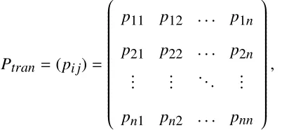
Fig. 2.1 shows that a Markov chain moves from one stateito another state j, called as the system transition whose probability is denoted by pi j. In general, fornstates discrete-time Markov chain, we can describe all its transition probabilities through then×n transi-tion matrixPtranas
Ptran =(pi j)=
p11 p12 . . . p1n p21 p22 . . . p2n
... ... ... ...
pn1 pn2 . . . pnn
, (2.2)
where due to the fact that system must transit to another state or remain its current state at
next time step,Ptranis constrained by
X
j
2.1.3
State Probability Formulation
WhenXk = i, we say that the chain is in stateiat discrete time stepkand the probability of finding the chain in this state is defined as
πk
i = P
Xk =i.
(2.4)
Using the state transitional probability, we can calculate the probability of finding
the chain in a particular state at next time step by
P
Xk+1 = j=
n
X
i=1
P[Xk+1 = j|Xk =i]
= n
X
i=1
πk ipi j.
(2.5)
Judging from above, it is obvious that a discrete-time Markov chain can be
com-pletely characterized by its transition probability matrix in (2.2), given the initial state
probability vectorπ0, where we define the state probabilities at time stepkas a row vector
πk =
πk
1, ..., π
k n
, (2.6)
andπkcan be calculated as
πk =π(k−1)P
tran =π(k−2)P2tran =...= π0Pktran, (2.7)
1
2
1
2
3
Figure 2.2: Periodic Markov chain.
2.1.4
Steady-state Behavior
2.1.4.1 Ergodic Markov chain
A discrete-time Markov chain is called as ergodic if it isirreducible, aperiodicand time-homogeneous, where time-homogeneous Markov chain has been discussed in previous Sec-tion and irreducible Markov chain is the one which has only one closed set and all states in
the chain can be reached from any other states. Mathematically, it indicates that there exist
ak,k∈[1,+∞), such that pki j> 0,∀i, j.
A Markov chain is said to be periodic if it only returns to a particular state after
nτ,(n = 1,2, ...) steps with τthe period. Otherwise, we call the Markov chain aperiodic. Fig. 2.2 shows an example of the periodic Markov chain.
2.1.4.2 Stationary distribution of Markov chain
Let k → ∞ for πk and Pktran, we have the steady characteristic of the Markov chain as
P = lim
k→+∞P
k
tran andπ = lim
k→+∞π
krespectively, which are independent of time step index
k. With regard to this, we call the Markov chain has steady state and π is the stationary distribution, calculated by
Customer population
Arriving
customers Departing
customers Waiting queue Service facility
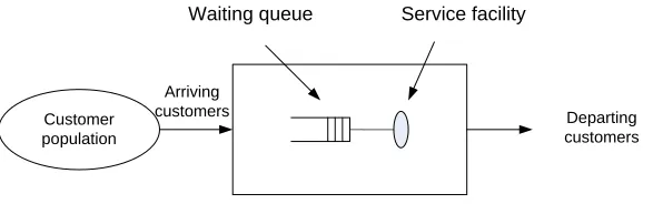
Figure 2.3: Schematic diagram of a queueing system.
According to the theorem in [2], every ergodic Markov chain does exist the stationary
distribution which is uniquely determined through the following equations:
π= πP, (2.9)
π.e= 1, (2.10)
whereedenotes the 1×nrow vector with all the entries equaling to one.
2.2
Queueing System
As depicted in Fig. 2.3, a queueing system is a place where customers arrive according to
an arrival process to obtain service from the service facility. Typically, a queueing system
is comprised of three major components: the input process, the system structure and the
output process.
2.2.1
Input Process
Arriving customers
Departing customers
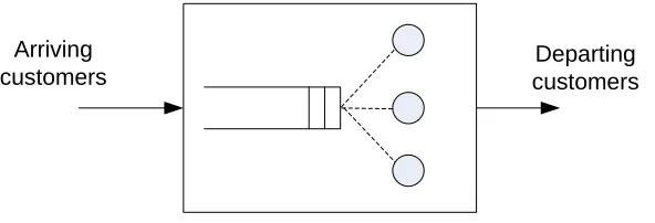
Figure 2.4: System structure of a queueing system: parallel servers.
• The size of arriving population: It may be assumed as either infinite or finite, where
for infinite arriving population, the number of external customers is very large
com-pared to that in the system and thus, the arrival rate will not be affected by the size. On
the other hand, finite customer population size is more involved because the arrival
process is affected by the number of customers which already exist in the system.
• Arriving patterns: This presents how the customers arrive at a queueing system and
can be determined by the inter-arrival time between two customers. In practice, a
probability distribution is fitted to characterize the time interval where the most
fre-quently adopted distribution in wireless communications is known as Markovian (or
Memoryless), which implies Poisson process.
• Behavior of arriving customers: The customers which arrive at a full queue due to
the finite length of the queue may either leave forever without entering the system,
called blocking system or come back after a short while.
2.2.2
System Structure
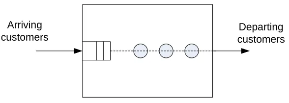
The service facility in Fig. 2.3 consists of one or more servers, categorized into the
paral-lel servers and the serial servers, shown in Fig. 2.4 and Fig. 2.5 respectively. In paralparal-lel
avail-Arriving customers
Departing customers
Figure 2.5: System structure of a queueing system: serial servers.
able for serving and leave the system after receiving the service, while for the serial servers,
the customer receives services from all or some of serial services before it leaves the
sys-tems. In this thesis, considering the practical situation in wireless communications, only
the parallel servers are investigated.
Another important characteristic to describe the system structure is the system
ca-pacity, referring to the maximum number of customers that the queueing system can deal
with, inclusive of those customers at the service facility. Specifically, in the parallel server
queueing systems, the system capacity is obtained by summing the maximum size of the
waiting queue and the number of servers.
2.2.3
Output Process
In general, there are five disciplines, which determine how the customers are selected for
services, those are first-come-first served (FCFS), last-come-first-served (LCFS), priority,
processor sharing and random. Among these disciplines, FCFS (also known as FIFO,
standing for first-in-first-out) is commonly adopted in wireless communications for the
ordered queue.
Similar to the arrival patterns, as every customer requires different amounts of service
times, a probability distribution could be used to describe the length of service times to the
2.2.4
Kendall Notation
To categorize and describe the different kinds of queueing systems, David G Kendall firstly
devised a shorthand notation with only single waiting queue considered in 1953. This
notation is known as Kendall notation, as follows [2]:
A/B/X/Y/Z
• A: Customer arriving pattern
• B: Service pattern
• X: Number of parallel servers
• Y: System capacity
• Z: Queueing discipline.
Taking M/M/1/∞ /FCFS as an example, it can be explained as a queueing system
where customers arrival is modeled by Poisson process and the exponentially distributed
service times from the server are requested. Moreover, the system has only one server,
an infinite queue length and the customers are served on a FCFS basis. For simplicity, in
practice, only the first three parameter are presented and by default, the last two parameters
are assigned with Y=∞and Z=FCFS respectively.
2.3
OFDM System
2.3.1
Concept of OFDM
OFDM which stands for orthogonal frequency division multiplexing, was firstly introduced
channels into a set of narrow band flat fading subchannels, the influences of inter-symbol
interferences (ISI) could be eliminated.
The time domain OFDM symbol can be expressed as
x(t)=
N−1 X
k=0
X(k)ej2πfkt, 0≤t <Ts, (2.11)
whereX(k) denotes the data transmitted on the k−thsubcarrier, N is the number of sub-carriers in the OFDM symbol andTs is the symbol duration. As for fk, it is the frequency
of thek−thsubcarrier, given by fk = f0+k∆f, where ∆f is the subcarrier spacing,
con-strained by the orthogonality condition in order to demodulate the OFDM signal for the
receiver, that isTs∆f =1.
Thanks to the orthogonal condition, it is evident that all the subcarriers are orthogonal
to each other, which can be easily demonstrated as follows [5]:
1
Ts Ts Z
0
ej2πfktej2πfkt∗dt
= 1
Ts Ts
Z
0
ej2π(fk−fl)tdt
= 1
Ts Ts Z
0
ej2π(k−l)∆f tdt
=δ[k−l],
(2.12)
whereδ[k−l] denotes the delta function, defined as [6]
δ[k−l]=
1, k= l,
Assuming the system samples x(t) at the interval ofTsa = TNs, the sampled symbol
can be obtained as
x(n)=
N−1 X
k=0
X(k)ej2πfknTN , n= 0,1,2, ...,N−1. (2.14)
Without loss of generality, let f0 =0. Therefore,
fkTs =Ts(f0+kδf)Ts= kTsδf = k, (2.15)
and (2.12) becomes
x(n)=
N−1 X
k=0
X(k)ej fk2πNkn =IDFT(X(k)), (2.16)
where IDFT is the abbreviation of inverse discrete Fourier transform, indicating that OFDM
modulation can be easily implemented using IDFT. In reality, inverse fast Fourier transform
(IFFT) which can reduce the number of complex multiplications fromN2 to N2 log2N for anN-point IDFT, is adopted for more efficient implementation of the OFDM system.
Furthermore, in order to eliminate the effect of time-dispersive multipath channel,
known as the intersymbol interference (ISI), a cyclic prefix (CP) whose length is required
to exceed the maximum excess delay of the multipath propagation channel is employed in
each OFDM symbol. A CP is typically a copy of the last part of one OFDM data symbol
and appended at the beginning of that symbol, as illustrated in Fig. 2.6.
2.3.2
OFDM Transmitter
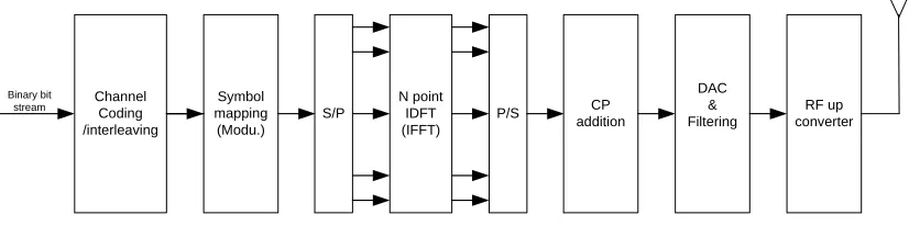
A block diagram of the OFDM transmitter is depicted in Fig. 2.7, and consists of a total of
Cyclic
Prefix OFDM Symbol
OFDM symbol with CP
Figure 2.6: The structure of OFDM symbol with cyclic prefix.
Channel Coding /interleaving Binary bit
stream mappingSymbol
(Modu.)
S/P
N point IDFT (IFFT)
P/S CP
addition
DAC & Filtering
RF up converter
Figure 2.7: Block diagram of OFDM transmitter.
(S/P) conversion, IFFT, parallel-to-serial (P/S) conversion, CP addition, digital-to-analog
conversion (DAC) and RF up conversion.
More specifically, the binary bit stream, which refers to the information to be
trans-mitted over the wireless channels, is first coded and interleaved for better bit-error-rate
(BER) performance, where the channel coding provides the ability of error detection and
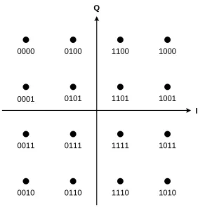
correction while interleaving reduces the impact of burst errors. Next, the symbol mapping
block converts the coded and interleaved bit stream into the symbol stream as shown in Fig.
2.8 where 16-QAM (Quadrature Amplitude Modulation) is given as an example. After that,
the symbol stream is re-organized via the serial to parallel conversion and then modulated
by IFFT where the pilots are inserted at this stage for channel synchronization and
estima-tion at the receiver. Following the P/S conversion, additional symbols are appended and the
appended symbol is then converted into an analog signal by the digital-to-analog converter
I Q
0000 0100
0001 0101
1100 1000
1101 1001
0011 0111
0010 0110
1111 1011
1110 1010
Figure 2.8: Constellation diagram for rectangular 16-QAM.
frequency and amplified before transmitted via the antenna.
2.3.3
OFDM Receiver
Fig. 2.9 shows the system blocks of the OFDM receiver where most blocks perform the
reverse functions of the transmitter. To be more specific, the received signal is first subject
to a band-pass filter and then down-converted to baseband signal, which is sampled by the
analog-to-digital converter (ADC). After synchronizing in both time and frequency domain,
CP is removed and the operated symbol is later processed by fast Fourier transform (FFT)
with the channel distortion compensated. At the final stage, the signal is demodulated,
Decoding /de-interleaving
Output Symbol
de-mapping (Demod.) S/P
N point DFT (FFT)
P/S CP
removal ADC
Filtering & RF down converter
Figure 2.9: Block diagram of OFDM receiver.
CP
CP CP CP
Original Symbol Channel Distorted Symbol
Ideal Transmission
Distorted Transmission
Figure 2.10: Elimination of ISI through cyclic prefix.
2.3.4
Advantages and Disadvantages of OFDM systems
The reason why OFDM is being widely deployed in modern systems and standards is that
it can significantly improve the performance of broadband wireless communications due to
the following advantages that it can achieve:
• Immunity to multipath fading: Given the length of the CP is larger than the maximum
excess delay of the multipath propagation channel, it is demonstrated in Fig. 2.10 that
the multipath interference from the preceding symbol can be absorbed by the CP of
current symbol. Therefore, by removing the CP before OFDM symbol demodulation,
the ISI is eliminated.
• Spectral efficiency: As show in Fig. 2.11, because of the orthogonal subcarriers
fre-Chapter 2: Basic Concepts Preview 19
In a classical parallel-data system, the total signal frequency band is divided into Nnonoverlapping frequency subchannels. Each subchannel is modulated with a separate symbol, and then theNsubchannels are frequency multiplexed. It seems good to avoid spectral overlap of channels to eliminate interchannel interference. However, this leads to inefficient use of the available spectrum. To cope with the inefficiency, the ideas proposed in the mid-1960s were to use parallel data and FDM with overlapping subchannels, in which each, carrying a signaling rateb,is spacedb apart in frequency to avoid the use of high-speed equalization and to combat impul-sive noise and multipath distortion, as well as to use the available bandwidth fully.
Figure 1.10 illustrates the difference between the conventional nonoverlapping multicarrier technique and the overlapping multicarrier modulation technique. By using the overlapping multicarrier modulation technique, we save almost 50% of bandwidth. To realize this technique, however, we need to reduce cross talk between SCs, which means that we want orthogonality between the different modulated carriers.
The word “orthogonal” indicates that there is a precise mathematical relation-ship between the frequencies of the carriers in the system. In a normal FDM system, many carriers are spaced apart in such a way that the signals can be received using conventional filters and demodulators. In such receivers, guard bands are intro-duced between the different carriers and in the frequency domain, which results in a lowering of spectrum efficiency.
It is possible, however, to arrange the carriers in an OFDM signal so that the sidebands of the individual carriers overlap and the signals are still received without adjacent carrier interference. To do this the carriers must be mathematically orthogonal. The receiver acts as a bank of demodulators, translating each carrier down to dc, with the resulting signal integrated over a symbol period to recover the raw data. If the other carriers all beat down the frequencies that, in the time domain, have a whole number of cycles in the symbol periodT, then the integration process results in zero contribution from all of these other carriers. Thus, the carriers are
Ch.1 Ch.2 Ch.3 Ch.4 Ch.5 Ch.6 Ch.7 Ch.8 Ch.9 Ch.10
(a)
(b)
Savings in bandwidth
Frequency
Frequency
Figure 1.10 Concept of the OFDM signal: (a) conventional multicarrier technique, and (b) orthogonal multicarrier modulation technique.
Figure 2.11: Bandwidth utilization comparison between the OFDM system and the conventional FDM system [7].
quency efficiency compared to the conventional FDM systems. Moreover, it
elimi-nates the inter-carrier interference (ICI) and leads to easier signal separation at the
receiver.
Besides, OFDM systems also have the benefits of flexible in resource allocation,
noise immunity, easy to integrated with other techniques and so forth [8]. However, on the
other hand, OFDM also has its drawbacks where the major issues are:
• High peak-to-average power ratio (PAPR): OFDM signals are the summation of all
the OFDM subcarriers, unavoidably resulting in the high PAPR which
correspond-ingly, requires large linear range of the DAC and power amplifier to avoid sever
clipping and non-linear distortion. This increases not only the power consumptions,
but also the complexity of the system implementation.
• Sensitivity to frequency offset and phase noise: OFDM systems can tolerate the time
offset because of the use of cyclic prefix which extends the symbol in time domain.
However, they could be very sensitive to the carrier frequency offset (CFO) and phase
noise, which may lead to the loss of orthogonality between subsymbols and thus,
• Capacity and power loss: Due to the transmission of the CP in OFDM symbols,
extra frequency resource and power have to be spent on those effectiveness symbols,
reducing the system capacity and power efficiency.
2.4
IEEE 802.11 WLAN
2.4.1
Overview of WLAN
A wireless local area network (WLAN) is a wireless communication system that uses radio
waves as the transmission media [10] to link the computers or workstations, and provides
a connection to the internet through an access point (AP). In recent years, WLAN is
ex-periencing tremendous growth and becoming increasingly popular, due to the efficiently
join data connectivity and mobility within a limited geographical area. A typical WLAN
consists of a wireless network interference card, known as station (STA), and a wireless
bridge referred to as an AP, which connects the wireless network to the wired network
(e.g., Ethernet LAN).
There are two main standards used in WLANs, namely the high performance radio
local area network (HiperLAN), proposed by European Telecommunications Standards
In-stitute (ETSI) [11], and the 802.11 standard proposed by IEEE [12], among which the
IEEE 802.11 standard is employed in most of the existing WLAN systems, also know as
Wi-Fi (wireless fidelity). IEEE 802.11 provides the regulations on designing the physical
(PHY) layer and the medium access control (MAC) layer for different vendors to operate
2.4.2
The PHY and MAC of WLAN
2.4.2.1 The physical layer
The physical layer of IEEE 802.11 WLAN is composed of two components: the Physical
Layer Convergence Procedure (PLCP) and the Physical Medium Dependent (PMD) layer,
where PLCP simplifies the provision of a physical service interface to the IEEE 802.11
MAC services while PMD provides a transmission interface used to send and receive data
between two or more STAs [12].
Three types of physical techniques are defined for WLAN, those are infrared light
(IR), frequency hopping spread spectrum (FHSS) and direct sequence spread spectrum
(DSSS), where IR works at the baseband and the other two operate at the licence-free
2.4GHz Industrial, Scientific, and Medical (ISM) band or the higher 5GHz Unlicensed
National Information Infrastructure (U-NII) band. Recently, due to the requirement for high
data rate, multiple-input multiple-output (MIMO) is taken into consideration in the new
IEEE 802.11n standard, which takes advantage of the multi-path environments, leading to
a potential capacity increment. The blew lists some examples of the physical layer in some
of the current standards [13]:
a. High-Rate Direct Sequence (HR/DS or HR/DSSS) used in 802.11b
b. Orthogonal Frequency Division Multiplexing (OFDM) used in 802.11a
c. Extended Rate PHY (ERP) used in 802.11g
d. MIMO used in 802.11n
2.4.2.2 The media access control layer
IEEE 802.11 MAC architecture can be described as shown in Fig. 2.12 as providing the
PCF (point coordination function) through the services of the DCF (distributed
Distributed Coordination function (DCF) Point coordination function (PCF)
Used for contention services and basis for PCF Required for
contention-free services
MA
C
ext
ent
Figure 2.12: IEEE 802.11 MAC architecture.
Figure 2.4: CSMA/CA basic access mechanism
sensing discovers whether the channel is busy or not through a clear channel assessment
function, the virtual carrier-sensing is optionally provided by the network allocation vector
(NAV). When any station is ready to transmit a frame, it must monitor the channel
before attempting to transmit. If the channel is sensed busy, the station must defer until
the channel is sensed idle for an interval of time equal to a distributed interframe space
(DIFS). Then, the STA goes into a random backoff time in which it sets a uniformly
random number from the interval [0, CW-1], where CW is called the contention window
size. For each unsuccessful transmission, the value of CW is doubled until reaching a
maximum value called CWmax; then, it resets to a minimum value called CWmin when
the frame is dropped or after a successful transmission. The backoff time is decremented
by one every idle slot, otherwise it is frozen. It resumes again after the medium is sensed
idle for a DIFS. The station can transmit when the backoff time reaches zero, and the
other stations hearing the transmission defer their transmissions by adjusting their NAVs.
If the frame is received successfully, an acknowledgement (ACK) is transmitted after a
short interframe space (SIFS) by the receiver. In DCF, if a transmitter does not receive
an ACK, it retransmits the frame and increases its CW size. The CSMA/CA basic access
mechanism is shown in Figure 2.4.
13
Figure 2.13: CSMA/CA basic access mechanism.
to be supported by all the STAs as defined in IEEE 802.11 specifications [14]. It is known
as carrier sense multiple access with collision avoidance (CSMA/CA) where the STA with
packets to transmit must contend for access to the channel. On the other hand, PCF uses a
point coordinator (PC) working at the access point to determine which STA currently has
the priority to transmit and provides the contention-free service as well as the QoS to some
real-time applications. In this section, we focus on detailing the DCF, while the details of
PCF can be found in [15, 16, 17].
To implement the DCF, two access mechanisms and two types of carrier-sensing
mechanisms are defined respectively, i.e basic access and request to send/clear to send
(RTS/CTS) access mechanisms, and physical carrier-sensing performed at air interface and
virtual carrier-sensing performed at the MAC sublayer. For the basic access model, when
Figure 2.5: CSMA/CA RTS/CTS mechanism
Unfortunately, the 802.11 standard cannot distinguish collisions from transmission
er-rors at the MAC layer, so it handles both of them as a transmission failure. Transmission
failure could occur due to collisions or transmission errors. Collisions may occur when two
or more stations start transmissions simultaneously while transmission errors may occur
due to the channel conditions such as fading, path loss, etc.
To deal with the hidden terminal problem, an optional four way hand-shaking technique,
known as the CSMA/CA RTS/CTS mechanism, is introduced. Before a station attempts
to transmit a frame, the transmitter sends a short RTS frame, 20 bytes, and the receiver
replies with a CTS frame, 14 bytes, if it is ready to receive. Once the transmitter receives
the CTS frame, it transmits the data frame. Other stations hearing an RTS update their
NAVs with the duration of the data frame transmission. Figure 2.5 shows the RTS/CTS
mechanism.
14
Figure 2.14: CSMA/CA CTS/RTS mechanism.
channel becomes idle for a distributed interframe space (DIFS) period and then starts a
random backoff timer. The backoff time is set as a uniformly random number from the
interval [0, CW-1], where CW denotes the contention window size. For each unsuccessful
transmission, the value of CW is doubled until reaching a maximum valueCWmaxor it is
set to a minimum valueCWminwhen the frame is either dropped or successful transmitted.
The STA decrements the backoff timer by one if the medium becomes idle for a DIFS
period, otherwise it freezes the timer. Upon the timer is decremented to zero, the STA
transmits its frame and an acknowledgement (ACK) will be reported by the receiver after
a short interframe space (SIFS) period of successfully receiving the packet. However, if
the ACK is missed caused by two or more STAs decrementing to zero simultaneously, the
STA will retransmit the frame with the increased CW size. The CSMA/CA basic access
mechanism is shown in Fig. 2.13.
For the sake of resolving the problem of hidden terminal in IEEE 802.11 WLANs,
which refers to the nodes within the interference range of the intended destination and
out of the carrier sensing range of the source [18, 19], an optional four way hand-shaking
technique, known as the CSMA/CA RTS/CTS mechanism is introduced, shown in Fig.
2.14. Before a STA attempts to transmit a frame, it sends a short RTS frame, and the
receiver replies with a CTS frame to indicate whether it is ready to receive. Once the
RTS update their network allocation vector (NAV) with the duration of the data frame
transmission.
2.5
Summary
In this chapter, we have reviewed some basic concepts to provide a basis for the rest of
this thesis. Firstly, the finite-state Markov chain which could be used to model the wireless
channels as well as the communication system was presented from the mathematics point of
view, followed by the introduction of the queueing system which is being broadly involved
in MAC layer queue status modeling. Then, two typical systems, namely the OFDM and
WLANs, based on which the works in this thesis are carried out, have been explained in
Chapter 3
Modeling of Wireless Communications for
Diverse QoS Provision
In wireless communications, it is necessary and challenging to guarantee diverse quality
of service (QoS) for various applications over wireless fading channels. In this chapter,
using the cross-layer approach [20], a finite state Markov chain system model with multiple
queues deployed at MAC layer is proposed to address the issue of diverse QoS provision
in wireless communications. We first model the physical (PHY) layer channel by finite
state Markov channel (FSMC) and then, combine FSMC with the queue status at MAC
layer to construct the finite state Markov chain model for the communication system. To
guarantee different queues with different priorities and provide the diverse QoS, a priority-based rate allocation algorithm, named as PRA algorithm, is introduced to distribute the physical layer data rate to the multiple MAC layer queues, where higher priority queue can
obtain larger data rate for transmission and vice versus, leading to diverse QoS provision
in the proposed system.
3.1
Introduction
One notable feature in nowadays wireless communications is the requirement of diverse
quality of service (QoS) provision, due to the various of applications, such as video/audio,
to different users is regarded to be a challenge because of the scarcity of wireless resources
(bandwidth and power), multipath fading channels and Doppler effects. Therefore, the
researches on guaranteeing QoS in wireless communications have drawn many researchers’
attentions recently [21, 22, 23, 24].
Facing the dramatic variation nature of wireless link, caused by Doppler effect and
multipath fading, it has been widely recognized to use finite-state Markov channel (FSMC)
to model such time-varying wireless fading channels, firstly proposed in [25]. FSMC
par-titions the received signal to noise ratio (SNR) into a finite number of intervals with each
interval representing a state of a Markov process [25, 26, 27]. Moreover, adaptive
mod-ulation and coding (AMC) is usually adopted to match the partitioned channel states by
changing the transmission parameters at the transmitter, bringing the benefits of attractive
rate and error performance [28, 29].
Using the cross-layer design approach, in [29], Liu et al. firstly combined the FSMC
channel at physical layer with the single queue at MAC layer to construct a new
finite-state Markov chain system model, for the sake of analyzing the long-time transmission
system performance. Originating from this work, lots of other subsequent researches have
been conducted to improve the wireless communication performance, such as the
energy-efficient wireless communications proposed in [30, 31]. Motivated by addressing the QoS
problems mentioned above, authors in [32, 33] used the MAC layer scheduling
mecha-nism to provide diverse QoS for different users, where different connections were assigned
different priorities and higher priority connection was scheduled earlier for better QoS.
However, most of the previous works using physical layer FSMC only assume single
MAC layer queue while employing multiple queues can introduce diversity to the
commu-nication systems and most importantly, bring the convenience of providing diverse QoS for
different applications. Therefore, we extend the work in [29] to a more general scenario,
and using the cross-layer technique, we use a finite state Markov chain to model the
com-munication system by combining the queues’ status at MAC layer with the FSMC channel
states at physical layer. Firstly, the physical layer slow-fading channel is modeled by a finite
state Markov channel (FSMC) and adaptive modulation and coding is adopted
correspond-ing to the channel states for the stable physical layer performance, i.e. a constant packet
error rate (PER) at physical layer. At MAC layer, the queues are considered to be finite
length and different queues handle the data with different QoS requirements. To diff
eren-tiate the multiple queues, a priority-based rate allocation algorithm is introduced, where
we assume that the physical layer transmission rate is allocated to the multiple queues
pro-portionally with the queue containing higher QoS requirement data obtaining larger data
rate. As a result, diverse QoS is provided to the multiple queues. Finally, deriving from the
multiple queue status at MAC layer, the channel state at physical layer and the proposed
PRA algorithm, a multiple dimensional finite state Markov chain is constructed to model
the communication system, and its QoS performance is analyzed and simulated to verify
the diverse QoS provision in the proposed system.
3.2
System Model
3.2.1
System Description
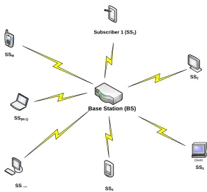
Fig. 3.1 shows a basic wireless communication systems, where multiple subscribers (SS)
are connected to the base station (BS) over the time-varying wireless channels. For different
users, they may transmit different kinds of data and thus require different QoS guarantee.
For instance, real time data such as voice and video, is more delay-sensitive while in the
mean time, some other kinds of data, such as file-based data requires zero-error tolerance
Client
Base Station (BS)
Subscriber 1 (SS1)
SS2
SS3
SS4
SS ... SS(M-1)
SSM
Figure 3.1: Wireless communication system diagram with a base station associated by multiple subscribers
AMC Controller
Fading Channel
AMC Selector Channel Estimator
Receiving Buffer
Fast Feedback Channel
Selected Mode Data with
Diverse QoS Demands
MAC Layer Multiple Queues
. . .
Queue 1
Queue 2
Queue n
Upper Layer
Transmitter (BS) Receiver (SS)
. . .
#1
#2
#3
#4
#N
pControl part Pilot
Ntsymbols
Npblocks
Ncsymbols
...
Figure 3.3: Physical layer frame structure
As for the wireless link between the BS and a SS, it is simply considered as shown
in Fig. 3.2, where M MAC layer queues are employed at the base station, and packets with similar QoS requirements are grouped in the same queue while packets with different
QoS requirements are in different queues. The data from the multiple queues are then
handled by the AMC controller and transmitted using certain transmission mode according
to the feedback from the receiver. At the receiver side, AMC selector is introduced to
determine the suitable modulation and coding scheme based on the estimated channel state
information (CSI). The decision of AMC selector is then reported to the AMC controller at
the transmitter through a fast feedback channel to update the transmission mode.
For the physical layer, we consider that it operates on a frame by frame basis where
each frame has a fixed time duration (Tf) and consists of a fixed number of symbols (Nt).
The frame structure is shown in Fig. 3.3, where symbols transmitted during each time frame
are grouped into two sections according to their applications, i.e. frame control section with
Ncsymbols and data transmission section withNd symbols. The frame control section can
be further divided into two parts, the pilot and the control part. The pilot is transmitted
with constant power and allows the receiver to estimate the instantaneous channel state
information while the control part contains the current transmission mode information,
used for demodulation and decoding at the receiver side. The data transmission section
consists ofNpMAC layer packets whereNp varies and depends on current communication
system condition. Using AMC mode k, each packet is modulated and coded with rateRk
Thus, the number of symbols transmitted per frame is obtained as Nt = Nc+Nd = Nc+
NpNb/Rk.
Besides the above descriptions, we next list some other assumptions for the proposed
system as follows:
• The queueing system is considered to be a blocking system, as discussed in chapter
2.2.1. To be more specific, the multiple queues at MAC layer are of finite-length
with the possibility of buffer overflow and arriving packets will be dropped once the
queues are full where the dropped packets will no longer be re-transmitted.
• packets arriving in time framet([tTf,(t+1)Tf)) are enqueued at time slot (t+1)Tf
and will be served in time framet+1.
• The wireless channel is modeled as slowly varying flat-fading channel and remains
constant for one time frame. However, the change of wireless channel between time
frames is allowed.
• Perfect channel state information estimated at the receiver side is available for both
the transmitter and the receiver.
• Multiple transmission modes are available with each mode, a combination of
spe-cific modulation scheme and a forward error correcting (FEC) code. Details of the
available transmission modes will be covered later.
3.2.2
Adaptive Modulation and Coding
For the purpose of maximizing the data rate, adaptive modulation and coding (AMC)
changes the modulation and coding mechanisms at the transmitter according to the
Table 3.1: Transmission Modes with UncodedMn-QAM Modulation
Mode 1 Mode 2 Mode 3 Mode 4 Mode 5 Modulation BPSK QPSK 8-QAM 16-QAM 32-QAM
Rk(bits/sym.) 1 2 3 4 5
ak 67.7328 73.8279 58.7332 55.9137 50.0552
gk 0.9819 0.4945 0.1641 0.0989 0.0381 γpk(dB) 6.3281 9.3945 13.9470 16.0938 20.1103
Table 3.2: Transmission Modes with Conventionally Coded Modulation
Mode 1 Mode 2 Mode 3 Mode 4 Mode 5
Modulation BPSK QPSK 8-QAM 16-QAM 32-QAM
Coding rateRc 1/2 1/2 3/4 3/4 3/4
Rk(bits/sym.) 0.5 1 1.5 3 4.5
ak 274.7229 90.2514 67.6181 53.3987 35.3508
gk 7.9932 3.4998 1.6883 0.3756 0.0900 γpk(dB) -1.5331 1.0942 3.9722 10.2488 15.9784
channel condition is estimated at the receiver and then, reported to the transmitter through
a special feedback channel.
Tab. 3.1 and 3.2 present two groups of typical transmission modes for the physical
layer, each of which is associated with a specific AMC scheme. In practice, as depicted in
Fig. 3.2, the AMC selector at receiver selects a particular mode according to current CSI
and report the result to the transmitter to update the transmission mode for next time frame.
The major benefits for AMC are two-fold [34], 1) higher data rata can be achieved
due to the rata rate maximization objective in AMC, which in turn increases the average
system throughput; 2) the variation of interference can be reduced since the transmitter
changes the modulation/coding scheme rather than adjusting the transmission power, to
cope with the channel condition.
On the other hand, the performance of AMC highly relies on the following factors
[35, 36]:
transmission mode for next time frame. In light of this, the AMC can only operate
efficiently in an environment where the channel is assumed to be relatively
slowly-varying, otherwise the selected modulation/coding scheme may not be fit for the
channel condition in next time frame.
• The transmission modes: Ideally, it is better to provide as many transmission modes
as possible, such that the channel condition can be most precisely matched. However,
the increasing of the available transmission modes increases the system
implementa-tion complexity as well. Therefore, there is a tradeoffbetween the AMC performance
and the system complexity, which needs to be carefully examined in the design of
AMC systems.
• The feedback mechanism: Since the wireless channels are time-varying, the feedback
of the CSI becomes an issue. It is necessary to assume a slowly-varying channel as
well as a reliable feedback to guarantee the performance of AMC. In this case, no
delay and transmission errors are allowed in the feedback channel to promise there is
no discrepancy existing between AMC mode selected at the receiver and mode used
for transmission at the transmitter.
3.2.3
Finite State Markov Channel
The modeling of the Rayleigh fading channel [37] using a Markov chain was firstly
pro-posed by Wang and Moayeri in 1995 [25], called as finite State Markov Channel (FSMC),
where the received SNR is partitioned into a finite number of non-overlapping
consecu-tive intervals with each interval representing a state of channel. FSMC are mathematically
derived from the discrete-time Markov chain as we discussed in Chapter 2.2, where the
Figure 2Partitioning the received SNR and assigning each interval to a state of the FSMC. Interval assigned to state n
Re c e iv ed SNR p01 p12 p11 p00 p10 p21 BSCs
State0 State1 State2 State
n-1 0 1 0 1 p0 1-p0 0 1 0 1 p1 1-p1 0 1 0 1 p2 1-p2 0 1 0 1 pn-1 1-pn-1
{
Figure 3The finite state Markov channel model representation.
Figure 3 shows the FSMC represented by a chain of ‘n’ states. As seen in the figure, only transitions to the same state or to adjacent ones are allowed in the model. In the figure the in-state
transition probabilities (pii) and the adjacent state transition probabilities (pij) are shown next to each
arrow in Figure 3.
The goal of the model is to relate the varying nature of the channel with a loss process. For this, each of the ‘n’ states is associated with a different binary symmetric channel (BSC). The ‘n’ BSCs are shown in the lower part of Figure 3. In each state the associated BSC determines how a symbol being transmitted, for example a zero or a one, could be received in error. The individual probabilities of
receiving a symbol in error are called crossover probabilities and are shown in the figure as 1-pi.
FSMC models are based on the theory of constant Markov processes3. Constant Markov
processes have the property that the state transition probabilities are independent of the time at which they occur. These processes can be defined by a finite number of possible states that are usually represented
3A Markov process with a discrete state space is also referred as a Markov chain [5, pg. 21]
time
Interval assigned to state 1
Interval assigned to state 0
9
Figure 3.4: Channel partitioning in FSMC [38]
3.2.3.1 Channel partitionings
To construct the finite state Markov channel model, we first partition the channel through
partitioning the received SNR into several intervals, as shown in Fig. 3.4. Numerous
channel partitioning schemes have been proposed in literatures, such as equal probability
partitioning, uniform partitioning, linearly increasing probabilities partitioning and so forth
[25, 26, 27, 39], among which the equal probabilities channel partitioning is being widely
deployed, where the threshold are selected in such a way that the state probability of being
in any state are equal [25].
We assume that the channel is partitioned into N + 1 intervals, corresponding to
N +1 channel states which are denoted by S = {S0,S1, . . . ,SN}. In order to maintain a prescribed packet error rate Pe at physical layer, adaptive modulation and coding is
em-ployed by adjusting the available transmission modesTmaccording to the CSI estimated at
the receiver, i.e. transmission modekis adopted when the channel is in stateSk,k∈[0,N].
The noise is assumed to be additive Gaussian noise (AWGN) with received SNRγ,
whose probability density function (PDF) follows exponential distribution as
p(γ)= 1
γ0exp − γ γ0
!
, γ≥0, (3.1)
In the presence of AWGN noise, the packet error rate can be approximated as
PER(γ)=
1, 0< γ < γpk
akexp(−gkγ), γ≥ γpk,
(3.2)
where k is the channel state index andγ is the received SNR. The parameters ak,gk and γpk are obtained by fitting (3.2) to the exact packet error rate.
We assume that the threshold of the partitioned received SNR for each state are
de-noted as Γ0 = 0 < Γ1 < Γ2 < . . . < ΓN = ∞ and the channel is defined in state Sk if
the received SNRγfalls in [Γk,Γk+1). Therefore, the steady state probabilityπkwhen the
channel is in stateSkcan be given by
πk =
Γk+1 Z
Γk
p(γ)dγ, k= 0,1, . . . ,N (3.3)
and correspondingly, the average packet error rate for channel stateSkis
PER(k)= 1 πk
Γk+1 Z
Γk
PER(γ)p(γ)dγ, k= 0,1, . . . ,N (3.4)
Searching-based channel partitioning scheme is adopted in our proposed model,
where it searches to find the threshold {Γk}N+1
k=0 such that the prescribed packet error rate
Pe is constant regardless of the channel states, that is PER(k) = Pe, ∀k. In this case, we
State 0 State 1 State 2 State N P01
P10 P21 P32 PN(N-1)
P12 P23 P(N-1)N
P00 P11 P22 PNN
…
Figure 3.5: N+1 finite state Markov channel
PER can maintainPeduring the whole transmission time, i.e. PER ≡Pe.
PER=
N
X
k=0
πk·PER(k)
=Pe N
X
k=0
πk
=Pe.
(3.5)
Below shows the detailed procedure of how the SNR thresholds {Γk}M+1
k=0 is
deter-mined using a searching mechanism.
Step a: Setk = N,Γk+1 = +∞.
Step b: For eachk, search for theΓk∈[0,Γk+1], such that PER(k)= Pe.
Step c: Ifk >1, setk =k−1 and go to Step b; otherwise, go to next step. Step d: SetΓ0 =0.
3.2.3.2 Channel state transition probabilities
Let {Si}, i = 0,1, . . . be a stationary Markov process, we get the transition probability, independent of time index as

![Figure 2.11: Bandwidth utilization comparison between the OFDM system and theFigure 1.10Concept of the OFDM signal: (a) conventional multicarrier technique, and (b)orthogonal multicarrier modulation technique.conventional FDM system [7].](https://thumb-us.123doks.com/thumbv2/123dok_us/7784539.1287291/35.612.178.471.106.242/utilization-comparison-conventional-multicarrier-orthogonal-multicarrier-modulation-conventional.webp)
![Figure 3.4: Channel partitioning in FSMC [38]](https://thumb-us.123doks.com/thumbv2/123dok_us/7784539.1287291/49.612.153.486.95.215/figure-channel-partitioning-in-fsmc.webp)
