Performance Analysis of Wind Energy
Conversion System Using Fuzzy Logic
Controller
J.Thangaraj1, Y.Levingstan2
Assistant Professor, Dept. of EEE, V V College of Engineering, Tisayanvilai, Tamilnadu, India1 Assistant Professor, Dept. of EEE, V V College of Engineering, Tisayanvilai, Tamilnadu, India2
ABSTRACT: This paper proposes a novel control strategy for the operation of direct driven Permanent Magnet Synchronous Generator (PMSG) based grid connected variable speed wind turbine (VSWT). VSWT driving a PMSG is connected to the power system through a fully controlled frequency converter, which supplies reactive power demand of the network during disturbance as well as extract maximum power from the wind. This improves the Low voltage ride through capability (LVRT) of the system without integration of any FACTS devices in the wind farm terminal. Fuzzy logic controller is employed for the control of pitch angle, real and reactive power flows of grid connected direct driven VSWT-PMSG system. The low voltage ride through (LVRT) Capability and dynamic performance of both fixed and variable speed WTGS are analyzed using Mat lab/Simulink software.
KEYWORDS: Permanent Magnet Synchronous Generator (PMSG), intelligent controller, Variable-speed wind turbine, Fixed Speed Wind Turbine, Low Voltage Ride through Capability (LVRT).
I. INTRODUCTION
Wind energy is playing a vital role in the world’s energy markets nowadays, considering its striking growth rate in the last few years. GWEC is predicting the global wind market to grow by over 155% from the current size reaching 240 GW of total installed capacity until 2012. This means a 146-GW increase in just five years . Due to this huge penetration of wind power to the grid, it is important to analyze both power quality and low voltage ride through (LVRT) issues of wind farms to meet the requirements of a new set of grid codes. Presently, variable speed wind turbine generator system (WTGS) is becoming more popular than that of fixed speed. Induction generators are used, in general, as fixed speed wind generator due to their superior characteristics such as brushless and rugged construction, low cost, maintenance free, and operational simplicity. However, it requires large reactive power to recover the air gap flux when a short circuit fault occurs in the power system, unless otherwise the induction generator becomes unstable due to the large difference between electromagnetic and mechanical torques, and then it requires to be disconnected from the power system. A shut- down of large wind farm may have a serious effect on the power system operation. Therefore, a new set of grid codes have been defined recently, which includes the LVRT requirements for WTGSs during the network disturbances to avoid the shutdown phenomenon of large wind farms.[1]
Permanent magnet machines are characterized as having large air gaps, which reduce flux linkage even in machines with multi magnetic poles [3], [4]. As a result, low rotational speed generators can be manufactured with relatively small sizes with respect to its power rating. Moreover, gearbox can be omitted due to low rotational speed in PMSG wind generation system, resulting in low cost. In a recent survey, gearbox is found to be the most critical component, since its downtime per failure is high in comparison to other components in a WTGS [4]. Moreover, PMSG wind generation system can supply more reactive power to the network than that of DFIG [5],[6]. Therefore, in this paper, PMSG is considered as variable speed wind generator to augment the LVRT capability of wind farm.
In this paper, a small scale new wind farm topology controlled by a new strategy is presented to augment the LVRT capability of fixed speed WTGS during network disturbances by using variable speed WTGS installed in the same wind farm. In the model system used in this paper, a VSWT driving a PMSG is connected to the power system through a fully controlled frequency converter, which consists of generator side ac/dc converter, Boost Converter, dc-link capacitor, and grid side dc/ac inverter. The intelligent control (Fuzzy logic control) technique is implemented for the control of pitch angle, real and reactive power flows of direct driven permanent magnet synchronous generator. The fixed speed WTGs driving a squirrel cage induction generators are directly connected to the grid.
These Fixed speed system uses the soft starter for smooth grid connection. Squirrel-cage induction machines consume reactive power and so it is conventional to provide power factor correction capacitors at each wind turbine [7].
Extensive simulation analyses have been carried out considering both symmetrical and unsymmetrical faults to analyze the LVRT characteristics of both fixed and variable speed WTGSs. Moreover, dynamic performance of the system is also verified.
II. MODEL SYSTEM
A 6 MW wind farm consisting of three 2 MW VSWT-PMSG wind turbines connected to a 25 kV distribution system exports power to a 120 kV grid through a 30 km, 25 kV feeder. The model system used for the LVRT and dynamic stability analyses are shown in Fig. 1.Two fixed speed wind turbines driving induction generators rated at 1.5 MW each are connected to the high voltage side of 575/25-kV transformer as shown in Fig. 1. A capacitor bank, Cbank has been considered to be connected to the terminal of each induction generator (IG) for reactive power compensation at steady state. The value of capacitor Cbank is chosen so that power factor of the wind generator during the rated operation becomes unity. Total output of the wind farm is supplied to the utility grid though a common step-up transformer ( 2 5 k v / 1 2 0 k v ) .
III.WIND TURBINE MODELING
The mathematical relation for the mechanical power extraction from the wind can be expressed as follows
PW=0 .5 ρ π R2 V∞3 Cp
(
λ,β)
... (1)
Where PWis the extracted power from the Wind, ρ is the air density, R is the blade radius [m], V∞ is the wind speed
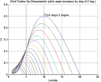
[m/s] and Cp is the power coefficient which is a function of both tip speed ratio λ and blade pitch-angle β [deg].Both fixed and variable
Fig.1 Model System
In variable speed wind turbine, when the wind speed changes, the rotational speed of wind turbine is controlled to follow the maximum power point trajectory. The range of rotor speed variation is, in general, approximately 5 to 16 rpm
Fig. 2 Cp- λ curves for different Pitch angle (FSWT)
During the control of generator side ac/dc converter, the maximum power, Pmax, is calculated based on the MPPT, which
becomes the reference power, Pref, for the converter. If this reference power is greater than the rated power of PMSG,
then the pitch controller shown in Fig. 4 is worked to control the rotational speed. Therefore, the PMSG output will not exceed the rated power. A conventional pitch controller shown in Fig. 5 is also considered in fixed speed WTGS. A VSWT-PMSG is decoupled from the grid through the frequency converter.
Fig. 4 Pitch Controller used in VSWT
Fig.5 Pitch Controller used in FSWT
IV. ELECTRICAL SCHEME
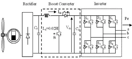
The electrical scheme of VSWT-PMSG topology is shown in Fig. 6
Fig.6 Electrical scheme of VSWT-PMSG
A. PMSG
In the simulation analyses, the PMSG model available in the package software MATLAB/SIMULINK is used. The nominal speed is considered as the maximum rotor speed, ωr_max. The pitch controller activates when the rotor speed exceeds the maximum rotor speed.
B. FREQUENCY CONVERTER
In this study, the direct drive VSWT-PMSG equipped with a fully controlled fr equen cy converter is used in the analyses. The frequency converter consists of rectifier, boost converter, and grid side DC/AC inverter. The inverter model is a standard 3-phase two-level unit, composed of six IGBTs and anti parallel diodes.
B-1. RECTIFIER:
The AC output vol tag e of PMSG i s converted t o DC voltage by a diode rectifier circuit. Cf is a filter
capacitance.
B-2. BOOST CONVERTER
Fig.7 Control block diagram of boost converter
B-3. GRID-SIDE INVERTER
Control block for the grid-side inverter is shown in Fig. 8, which is developed based on the cascaded control scheme. The d-q quantities and three-phase electrical quantities are related to each other by reference frame transformation. The angle of the transformation is detected from the three phase voltages (Va, Vb, Vc) at the high voltage side of the grid side transformer. The DC voltage of the link capacitor is controlled constant by the fuzzy controllers. The DC-link voltage can be controlled by the d-axis current. On the other hand, the reactive power of grid-side inverter can be controlled by the q-axis current. The reactive power reference is set in such a way that the terminal voltage at high voltage side of the transformer remains constant.
V. FUZZY LOGIC CONTROL
An aeolic-electric energy conversion process involves the air masses complex dynamics, the wind regime stochastic nature and the turbine and generator non-linear behavior. In such kind of applications, the fuzzy-logic based controllers have shown better performance and some others advantages [8]: The mathematical model is not necessary to controller synthesis; it tolerates parameter imprecision or parameter variations; and, allows the agreement between contradictory control actions, just as occurs in the aeolic- energy capture that have to be maximum, since it do not exceed the generator power limit.
Fig.8 Control Block for Grid side converter
The block diagram illustrated in Figure 9 exhibits the basic structure of the fuzzy-logic controllers, where each input is evaluated by gaussian membership functions, so that the membership degree of the fuzzy sets is associated to each input. Finally, the defuzzyfication is obtained by the centroid method. The captured aeolic-energy amount control is made by means of the aeolic-turbine power coefficient and has two objectives: first, under low winds is to maximize the captures aeolic-energy; second, under strong winds is to limit the capture of aeolic-energy, in order to maintain the PMSG operating at full-load. So, this control maintains the pitch-angle α=0°, while the output power of PMSG does
full-load operation of PMSG.
Fig.9 Block diagram of fuzzy controllers
The aeolic-energy capture controller determines the pitch-angle variations “Δα” from the PMSG output power “Pg”, from PMSG output power variations “ΔPg”, and from the pitch-angle “α”, w h e r e t h e a c r o n y m m e a n s : ” N B ” N e g a t i v e b i g , ” N M ” n e g a t i v e m e d i u m , ” N S ” Negative small, ‘ZE’ zero, ”PS” positive small, ”PM” positive medium, ”PB” positive big.The rule base is composed by the following rules:
If error is “NB” then control signal is “NB”
If error is “NM” then control signal is “NM”
If error is “NS” then control signal is “NS”
If error is “ZE” then control signal is “ZE”
If error is “PS” then control signal is “PS”
If error is “PM” then control signal is “PM”
If error is “PB” then control signal is “PB”GIRD SIDE CONTROLLER: The speed and reactive power c o n t r o l l e r s have similar fuzzy inference systems and the same rule base whose inputs are the error “e” and, the output is the variations of the control action “Δu”. The fuzzy controller keeps the DC link voltage constant.
Fig.10 Characteristics of LVRT
VI. SIMULATION RESULTS
both fixed and variable speed WTGS. Simulations are carried out using Mat lab/Simulink software. Time step and simulation times ar e chosen 0.00002s an d 5s respectively. Two cases are considered in the simulation study to show the effectiveness of the control strategy of the proposed system to meet the wind farm grid code requirements.
TABLE 1
Case 1 (PMSG+IG)
Case 2 (IG Only)
IG1(3MW) IG1(3MW) IG2(3MW) IG2(3MW) PMSG(6MW) IG(6MW)
For case 1 the simulation results are obtained by considering both VSWT and FSWT and for case 2 the fixed speed system only considered.
A.LVRT ANALYSIS (3LG FAULT):
CASE1:
Fig11 a).Terminal voltage Vabc(pu)
Fig 11 a. shows the Variation of line Voltage of Variable speed system as well as of fixed speed system during the 3L-G fault condition. From this figure we can conclude that the terminal voltage of fixed speed system was supported by variable system during symmetrical fault condition. (3L-G fault condition)
Fig11.b).Reactive power (pu)
Fig11.c). Rotor Speed (pu)
Fig 11 c. shows the variation of Rotor Speed of Variable speed system as well as of fixed speed system during the 3L-G fault condition.
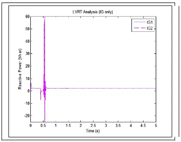
CASE 2: FSWT- IG ONLY (3LG FAULT):
Fig12.a) Terminal voltage Vabc (p.u)
Fig 12 a. shows the Variation of line Voltage of fixed speed system during the 3L-G fault condition. From this figure we can conclude that the LVRT requirement of grid was not met by considering fixed speed system only. (3L-G fault condition)
Fig 12 b. shows the reactive power requirement in order to support voltage dip of fixed speed system during the 3L-G fault condition.
Fig12.c) Rotor Speed (p.u)
Fig 12 c. shows the variation of Rotor Speed of fixed speed system during the 3L-G fault condition.
From the simulation results it’s clearly shown that the grid side inverter can provide necessary reactive power during the severe symmetrical 3LG fault which is shown in Fig.11.b. Therefore, the terminal Voltage shown in Fig. 11.a. can return to its pre-fault level for Case1. From Fig. 11.a, it is seen that Case 2 fails (Fixed Speed IG) to achieve the LVRT requirement of wind farm due to lack of reactive power supply during network disturbance. The response of PMSG rotor speed is shown in Fig. 11.c. and for fixed speed system is shown in fig 12.c. From this the rotor speed increases twice for severe 3LG fault for fixed speed system where as very small fluctuation in rotor speed for VSWT-PMSG+FSWT-IG and returns to its nominal value quickly.From the simulation results, it is seen that the LVRT requirement of wind farm can be met well for the fault types described in this paper by the VSWT-PMSG is superior to that of fixed speed system.
B. DYNAMIC PERFORMANCE ANALYSIS:
To demonstrate the global performance of the VSWT-PMSG system, it is simulated for three wind regimes, and the results are following:
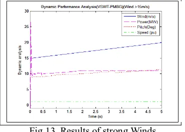
Under Strong Wind(>15m/s):The turbine rotates with maximum angular speed, while the pitch angle limits the Aeolic energy capture and maintains the nominal value of output power (Fig.13).
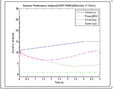
Under Medium Wind (between 11-15m/s):The turbine searches constantly the optimum value of angular speed to maximize its power coefficient; during the wind-speed peaks, the pitch-angle limits the energy capture, and maintains the output power in its nominal value (Fig. 14).
Under weak winds(<11m/s): The turbine rotates slowly, but still searches the optimum value of angular speed, while the pitch-angle keeps at 0° (Fig.15).
Fig 13. Shows the results of strong wind conditions. From this fig under strong wind (>15 m/s) condition, in order to extract the maximum power from the wind, and for safe operation of wind turbine the pitch angle was maintained at an angle of 12 degree. Due to this the wind other than required for producing rated power was bypassed.
Fig.14 .Results of medium wind
Fig14.Shows the results of medium wind conditions. From this fig under medium wind (11-15 m/s) condition, in order to extract the maximum power from the wind, pitch angle was maintained at an angle of an angle of 4 degree.
Fig.15 .Results for weak winds
Fig 15. Shows the results of weak wind conditions. From this fig under weak wind (<11 m/s) condition, in order to extract the maximum power from the wind, the pitch angle was maintained at an angle of 0 degree.
VII. CONCLUSION
A novel control strategy for the operation of direct driven Permanent Magnet Synchronous Generator (PMSG) based grid connected variable speed wind turbine has been proposed. Fuzzy logic controller have shown better performance than the other controllers since it controls pitch angle, real and reactive power flows of grid connected direct driven VSWT-PMSG system. The results obtained for symmetrical faults were only shown for simplicity. Moreover, the dynamic performance is verified under three real regimes of wind speed data. Finally, it is concluded that the proposed system can be a cost-effective solution to achieve the requirements of new wind farm grid code and these results shows that VSWT-PMSG system has superior performance over fixed speed system.
REFERENCES
1. D. Hansen and G. Michalke, “Modeling and control of variable speed multi-pole permanent magnet synchronous generator wind turbine,”
2. S. M. Muyeen, M. H. Ali, R. Takahashi, T. Murata, J. Tamura, Y. Tomaki, A. Sakahara, and E. Sasano, “A comparative study on transient stability analysis of wind turbine generator system using different drive train models,” IET Proc. Renewab. Power Gen. (IET-RPG), vol. 1, no. 2, pp. 131–141, Jun. 2007.
3. H. Polinder, F. F. A. Van der Pijl, G. J. de Vilder, and P. J. Tavner, “Comparison of direct-drive and geared generator concepts for wind turbines,”IEEE Trans.Energy Converts., vol. 3, no. 21, pp. 725–733,Sep. 2006.
4. S. Morimoto, H. Nakayama, M. Sanada, and Y. Takeda, “Sensor less output maximization control for variable-speed wind generation system using IPMSG,” IEEE Trans. Ind. Appl., vol. 41, no. 1, pp. 60–67, Jan. 2005.
5. Fujin Deng, Zhe Chen “Low-Voltage Ride-Through of Variable Speed Wind Turbines with Permanent Magnet Synchronous Generator.”
IEEE Trans. Ind. Appl., vol. 41, no. 1, pp55-60 Jan. 2009.
6. M. J. Hossain, H. R. Pota, V. Ugrinovskii, “Decentralized Control to Augment LVRT Capability of Wind Generators with STATCOM/ESS” IEEE conference on Power Electronics, June2010.
7. S. M. Muyeen, M. A. Mannan, M. H. Ali, R. Takahashi, T. Murata, and J. Tamura,“Stabilization of wind turbine generator system by STATCOM,” IEEJ Trans. PE, vol. 126-B, no. 10, pp. 1073–1082, 2006.
8. AMÊNDOLA, C. A. M. GONZAGA, D. P. Fuzzy- Logic Control System of a Variable-Speed Variable-Pitch Wind-Turbine and a Double-Fed Induction Generator,”IEEE. Seventh International Conference on Intelligent Systems Design and Applications” 2007.
9. L. Zhang, C. Shen, M. L. Crow, L. Dong, S. Pekarek, and S. Atcitty, “Performance indices for the dynamic performance of FACTS and FACTS with energy storage, “Elect. Power Common. Syst., vol. 33, no.3, pp. 299–314, Mar. 2005.
10. K. Tan and S. Islam, “Optimal control strategies in energy conversion of PMSG wind turbinesystem without mechanical sensors,” IEEE Trans. Energy Converts., vol. 19, no. 2, pp. 392- 399, Jun. 2004.
B I O G R A P H Y
Mr.J.THANGARAJ was received the B.E Engg.degree from the department of Electrical and Electronics Engineering at The Rajaas Engineering College, Vadakkangulam, affiliated to Anna University, Chennai in 2005. He received his M.E.degreee from the department of Power Systems Engineering at S.K.P. Engineering College, Tiruvannamalai, affiliated to Anna University Chennai, 2012.He has 5years of industrial experience in the field of Wind Energy & 2.7 years in teaching field. Presently he is Working as an assistant professor at V V College of Engineering, Tisayanvilai, Tamilnadu.