Dynamic Voltage Restorer with a Battery
Energy Storage System Using PI Controller
N. Kesava Varma1, S.V.R Lakshmi Kumari2
PG Student [PSEG], Dept. of EEE, V.R.S.E.C, Vijayawada, India1
Associate Professor, Dept. of EEE, V.R.S.E.C, Vijayawada, India2
ABSTRACT: Power Quality is an occurrence as a non-accurate current, voltage or frequency that creates a failure in or mal operation of end user equipment. Power Quality problems include voltage sags, swells, momentary disruptions, spikes, surges and harmonic distortions. Voltage swells and sags are common eventsof power quality problems in electric power systems. A dynamic voltage restorer (DVR) is a series-connected FACTS controller used for mitigatingvoltage sags, swells and also harmonics in power system network. In this paper, the dynamic voltage restorer is operated with a battery energy storage system and compared with the self-supported DVR. SRF theory is used for converting the voltages to the stationary frame from rotating vectors. The mitigation of voltage swell, sag and harmonics using DVR with a battery energy storage system is simulated in MATLAB.
KEYWORDS: Dynamic voltage restorer (DVR), power quality, unit vector, voltage harmonics, voltage sag, voltage swell.
I.INTRODUCTION
energy-II. OPERATION OF DVR
Fig. 1. Basic circuit of DVR.
The figure of a DVR connected system is shown in Fig. 1. Vinjis the inserted voltage of the DVR then the load voltage
Vload is to be maintained same magnitude and is not distorted, even though the supply voltage Vsis not to be maintained
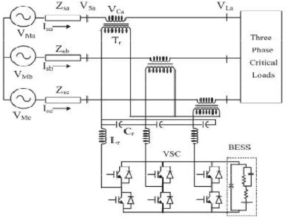
constant magnitude or is distorted.Fig. 2. Showsa figure of a three-phase DVR connected to rebuild the voltage of three-phase load. A three-phase supply is connected critical and sensitive load through a three-phase series transformer. the supply of phase A VMa is connected to the (PCC) point of common couplingVSa through a short-circuit impedance
Zsa. The voltage inserted by the DVR in phase A VCa is that the load voltage VLais of same magnitude and not distorted.
A three-phase DVR is connected to transmission line to insert a voltage in series using three phase transformers. Tr,
Crand Lrare represented the filter components used for eliminating the ripples in theinserted voltage. A three-leg VSC
with insulated-gate bipolartransistors (IGBTs) is used as a DVR, and a battery is connected to its dc link.
III
.C
ONTROL OFDVR
The mitigation for voltage sags using a DVR can be performed by inserting or absorbing the reactive power or the active power. When the inserted voltage is in quadrature with the current at the fundamental frequency, the compensation is done by inserting reactive power and the Dynamic Voltage Restorer is with a capacitor-supported dc bus. However, if the inserted voltage is same phase with the current, DVR inserts active power, and hence, a battery is needed at the dc bus of the VSC. The control technique considers the limitations, they are the voltage injection capacity (transformer rating and converter) and optimization of the energy storage device.
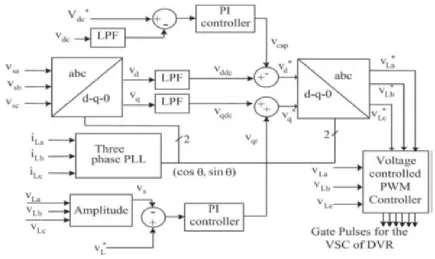
Fig. 3. Control block of the DVR uses SRF method
Fig. 3. shows a control block of the DVRin which the SRF theory is used for reference signal estimation. Voltage at where DVR is connected to the transmission line (PCC) Vs are to be converted to the rotating reference using Park’s
Fig. 4. Simulink Model of battery-supported DVR-connected system
IV. MODELING AND SIMULATION
The DVR connected system consists of a three-phase power supply, three-phase critical loads, and the three-phase series injection transformer shown in Fig. 2 is modeled in MATLAB/Simulink software along with a sim power system toolbox and is shown in Fig. 4. An equivalent load considered is a 10-kVA 0.8-pf lag linear load. The parameters of the considered system for the simulation study are given in the Appendix.The control algorithm for the Dynamic Voltage Restorer shown in Fig. 3 is also modeled in MATLAB software. The reference DVR voltages are obtained from sensed PCC voltages (vsa, vsb, vsc) and load voltages (vLa, vLb, vLc). A PWMcontroller is used over the reference and sensed DVR voltages to generate the gating signals for the Insulated Gate Bipolar Transistors (IGBTs) of theVSC of the DVR.The capacitor-supported DVRis also modeled and simulated in MATLAB, and the performances of the systems are compared in three conditions of the DVR.
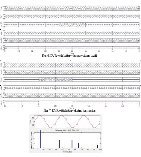
Fig. 6. DVR with battery during voltage swell
Fig. 7. DVR with battery during harmonics
Fig. 9. Load voltage and harmonics during disturbance
V. PERFORMANCE OF THE DVR SYSTEM
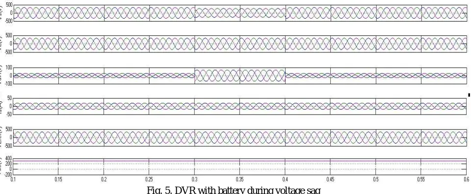
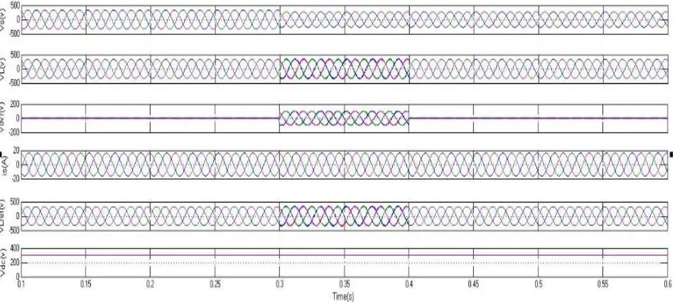
The performance of the DVR is simulated in MATLAB software for different supply voltage power quality problems such as voltage swell, sag. Fig. 5. Shows the transient performance of the system under voltage sag condition. At 0.3 s, a sag is applied for 5 cycles and in fig. 6. Shows the performance of the system under swell condition. A swell is applied at 0.3 s for 5 cycles. It is observed that the load voltage maintained same magnitude and undistorted under both sag and swell conditions. load voltages vL, PCC voltages vs, source currents is reference load voltages vLref and dc
bus voltages vdc are also depicted in fig. 5&6. The compensation of harmonics in the supply voltages is shown fig. 7. At
0.2 s the supply voltage is distorted and continued for five cycles. After injecting the DVR voltage, the load voltage is maintained at same magnitude and not distorted. The total harmonics distortions (THDs) of the voltages at the PCC and load voltages are shown in fig. 8-9, respectively. It is observed that the load voltage total harmonic distortion is decreased to a level of 0.41% from the PCC voltage of 8.37%.
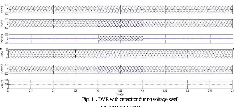
Fig. 11. DVR with capacitor during voltage swell
VI. CONCLUSION
The operation of a DVR has been demonstrated with a battery energy storage system and compared with the capacitor supported DVR. The reference load voltages estimated using the method of unit vectors, Synchronous reference frame theory (SRF) is used for converting the voltages to the stationary frame from rotating vectors. It is concluded that compensation of voltage sag, swell and harmonics using DVR with a battery is show better results compared to capacitor supported Dynamic Voltage Restorer.
APPENDIX
AC line voltage : 415 V, 50 Hz
Line impedance : Ls= 3.0 mH, Rs= 0.01 Ω
Linear loads : 10-kVA 0.80-pf lag Ripple filter : Cf= 10 μF, Rf= 4.8 Ω
DVR with BESS
DC voltage of DVR : 300 V AC inductor : 2.0 mH
Gains of the d-axis PI controller : Kp1 = 0.5, Ki1 = 0.35
Gains of the q-axis PI controller : Kp2 = 0.5, Ki2 = 0.35
PWM switching frequency : 10 kHz
DVR with dc bus capacitor supported
DC voltage of DVR : 300 V AC inductor : 2.0 mH
DC bus voltage PI controller : Kp1 = 0.5, Ki1 = 0.35
AC load voltage PI controller : Kp2 = 0.1, Ki2 = 0.5
PWM switching frequency : 10 kHz
Series transformer : three-phase transformer of rating 10 kVA, 200V/300 V.
[3] M. H. J. Bollen and I. Gu, Signal Processing of Power Quality Disturbances. Hoboken, NJ, USA: Wiley-IEEE Press, 2006.[4] R. C. Dugan, M. F. McGranaghan, and H. W. Beaty, Electric Power Systems Quality, 2nd ed. New York, NY, USA: McGraw-Hill, 2006.
[4] A. Moreno-Munoz, Power Quality: Mitigation Technologies in a Distributed Environment. London, U.K.: Springer-Verlag, 2007.
[5] K. R. Padiyar, FACTS Controllers in Transmission and Distribution. New Delhi, India: New Age Int., 2007, IEEE Recommended Practices and Recommendations for Harmonics Control in Electric Power Systems, IEEE Std. 519, 1992.
[6] V. B. Bhavraju and P. N. Enjeti, “An active line conditioner to balance voltages in a three phase system,” IEEE Trans. Ind. Appl., vol. 32, no. 2, pp. 287–292, Mar./Apr. 1996.