Division 4 – Characterisation of Loads
SEISMIC ANALYSIS OF THE TOKAMAK COMPLEX BUILDING OF
ITER FUSION FACILITY
Didier Combescure1, Jordi Ayneto1, Fernando Rueda2, Luis Maqueda2, Luis Moya2, Jorge Olalde2, Victor Domínguez2, Xiaotan Zhang3, Tyge Schioler3, Giulio Sannazzaro3, Laurent Patisson3
1
Fusion for Energy (F4E), ITER Dept, Technical Support, Barcelona, Spain (didier.combescure@f4e.europa.eu)
2
ESTEYCO, Madrid, Spain
5
ITER Organization, Route de Vinon sur Verdon, 13115 Saint Paul Lez Durance, France
ABSTRACT
As for all the nuclear facility, the ITER Fusion reactor and its mechanical components have to be designed to sustain seismic forces. The ITER facility is under construction in Cadarache, France, and the requirements from the French nuclear regulator (ASN) are strictly followed. The Tokamak Complex is the core of the ITER facility. It is a single structure which comprises the Tokamak, the tritium and the diagnostic buildings and its total weight is around 300,000 tons. The structure has a footprint of about 125 x 90 m and it is being built with a base isolation system made of reinforced low damping neoprene pads. The 1.5m thick upper basemat supports the 23,000.00 tons of the Tokamak machine where the fusion reaction will take place.
The transfer of the seismic accelerations and their spectra from the ground to the components located in the Tokamak complex may be challenging in case of design change in important structures/components and in case of coupling and interaction between the secondary components and the supporting structure.
This paper presents a set of seismic analysis performed in order to determine and control the floor response spectra inside the Tokamak complex building. The seismic FRS have been generated with several FE models corresponding to different design/construction stages. An independent model has also been developed in order to assess the impact of the evolution in the loading drawings implementation and the modelling strategy (solid versus shell model, representation of the main equipment, etc.).
INTRODUCTION
ITER (https://www.iter.org) is probably the most ambitious energy project in the world today, whose main objective is demonstrating the scientific and technical feasibility of nuclear fusion as an energy source. 35 nations are collaborating to build the world's largest tokamak fusion reactor, a magnetic fusion device that has been designed to prove the feasibility of fusion as a large-scale and carbon-free source of energy based on the same principle that powers our Sun and stars.
The experimental campaign that will be carried out at ITER is crucial to advancing fusion science and preparing the way for the fusion power plants of tomorrow. ITER will be the first fusion device to produce net energy, maintain fusion for long periods of time and test the integrated technologies, materials, and physics regimes necessary for the commercial production of fusion-based electricity.
The ITER design must face a large variety of potential threats and complex loads, including seismic events. These are a design driver for many of the ITER buildings and main mechanical components, including the Tokamak machine and the building that supports it: the Tokamak Complex. The Tokamak Complex is a reinforced concrete building that houses the 23,000-ton Tokamak machine, where the fusion reaction will take place. The Tokamak Complex is more than 70 m high, its plan dimensions correspond to those of a standard football stadium and it will become one of the largest seismically isolated structures ever built.
As a nuclear facility, the seismic design of ITER must ensure the corresponding seismic safety requirements are met according to the French regulation. On the other hand, too conservative approaches may have important technical and financial consequences.
This article provides a global summary of the latest works carried out by the European Domestic Agency, Fusion for Energy (F4E, http://fusionforenergy.europa.eu/) in collaboration with IO-CT, for the definition of the seismic environment within the ITER Tokamak Complex. This includes the derivation of seismic floor response spectra as well as the characterisation of the complex interface seismic forces between the Tokamak machine and the building, which are critical for a correct design of the corresponding supporting elements.
GENERAL DESCRIPTION OF ITER TOKAMAK COMPLEX AND SEISMIC REQUIREMENTS
The ITER Tokamak Complex
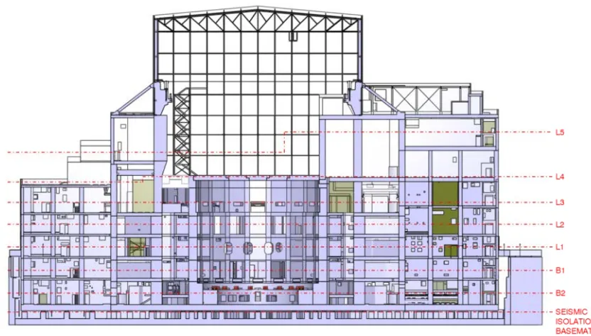
The ITER Tokamak Complex (see Figure 1) is a rectangular reinforced concrete building, roughly 125 m long and 90 m wide, partially embedded in an excavation, called the seismic pit, supported by reinforced concrete lateral walls and a 1.5 m thick basemat. The foundation is on a fairly compact and homogeneous rock , limiting the potential significance of soil-structure interaction effects.
The building structure is seismically isolated from the seismic pit basemat by 493 anti-seismic bearings (ABSs) which support the bottom basemat of the entire building. The ASBs are 900x900 mm2 pads mounted on top short columns (“plinths”) that come out the seismic pit basemat.
The bottom basemat of the building is an, again, 1.5 m thick reinforced concrete slab locally strengthened at the centre of the Tokamak building to support the Tokamak machine, which is surrounded by a thick cylindrical wall: the bioshield wall. The whole Tokamak Complex reinforced concrete structure rests on this basemat.
The ITER Tokamak Machine
The ITER experiment builds on the concept of the tokamak, a torus continuous double-wall vessel surrounded by coils that produce a magnetic cage to confine the high-energy plasma. The ITER Tokamak machine (see Figure 2) will be 24 metres high, 30 metres wide and weight around 23000 tons. The most relevant components of the Tokamak machine from a global dynamic point of view are:
- The 10000 tons superconducting magnets in charge of producing the magnetic fields to initiate, confine, shape and control the plasma.
- The Vacuum Vessel, a 8000 tons stainless steel chamber that houses the fusion reactions and acts as main first safety containment barrier.
-
The 3800 tons cryostat, a stainless steel chamber (29 x 29 m) surrounding the vacuum vessel and superconducting magnets to ensure a cryogenic high vacuum environment.
© ITER Organization
Definition of the Seismic Action
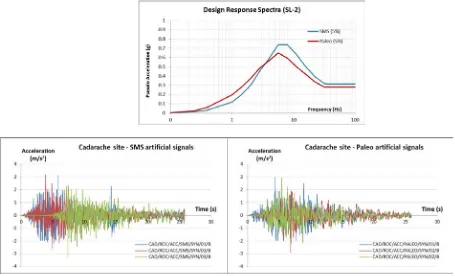
The design earthquake for ITER (Safe Shutdown Earthquake –SSE or SL-2-) is generated as the envelope of two seismic events: the “Seisme Majore de Securite” (SMS) and the paleoseism. Figure 3 shows the horizontal SL-2 response spectra, both for SMS and Paleo earthquakes, at the control point (ground surface level). The Zero Period Acceleration (ZPA) is equal to 0.315g. The vertical motion is derived by multiplying the horizontal motion by 2/3. Six artificial signals (three for the SMS and three for the Paleo) for the horizontal accelerations are also shown in Figure 3, which are representative of the design response spectra and meet the statistical independence requirements of the (ASN/GUIDE/1/01).
Figure 3. Design response spectra and artifical acceleration signals for SL-2 (horizontal).
OVERVIEW OF SEISMIC ANALYSES
Dynamic Representation of the Structures and Components Involved
Significant efforts have been devoted to entirely base this new independent dynamic FE model of the Tokamak Complex on completely up-to-date design information, since the tracking of the latest design and configuration management changes, especially regarding mass control, has been given the highest priority in such a complex and multidisciplinary project.
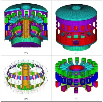
Additionally, a global dynamic FE representation of the Tokamak machine developed by ITER Organization has been assembled to the independent Tokamak Complex FE representation described above. This is shown in Figure 5, where specific machine parts are depicted, namely, cryostat (2*), central solenoid, poloidal and toroidal field coils (3*), and vacuum vessel and the extension ports (4*).
Figure 5. Global dynamic FE model of the ITER Tokamak machine – ITER Organization
(1)
VV and cryostat (2) Cryostat (3) Magnet (4) Vacuum Vessel
Reference Methodology
The seismic response of the Tokamak Complex has been obtained based on time history analyses of the assembled FE representations described in the previous subsection, in which the dynamic response of the system is obtained as a linear combination of its modal responses. That is, the dynamic equations of motions are integrated for the modal coordinates of the system, which is thus assumed to be linear and elastic. Additional activities to address the significance of some potential non-linear effects are ongoing and it is foreseen to have a first set of results in 2017. The dynamic equations of motion have been integrated using the implicit HHT algorithm with a time step equal to 10-3 seconds. The resulting absolute displacements have been stored at every time step and used to obtain the acceleration time histories.
In order to account for uncertainties related to the mechanical properties of the different materials: soil, seismic isolation pads and concrete, lower bound (LB) and upper bound (UB) sets of analyses with different FE models have been carried out.
earthquake (SMS and Paleo, see Figure 3) have been simultaneously combined to generate three different seismic scenarios. A total of six scenarios have been therefore analyzed for each LB or UB FE model, which already include the combination of the three spatial directions.
SUMMARY OF RESULTS
Seismic FRS within the Tokamak Complex (TKC)
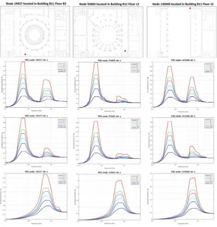
A reference set of seismic FRS have been generated by F4E and IO based on the results obtained from the official Tokamak Complex FE representation developed by the Architect Engineer. A relatively large sample of monitoring points has been selected for the determination of seismic FRS, resulting in more than a thousand locations throughout the Tokamak Complex. These constitute a representative sample for the potential statistical treatment of the resulting data or the determination of envelopes room by room or level by level. A full detailed set of FRS has been derived for reference damping levels (0.5%, 2%, 4%, 5%, 7%, 10% and 20%, see Figure 6), whereas maps of key spectral quantities (peak and ZPA values, see Figure 7 for one representative floor) have been obtained for all the monitored points and graphically represented level by level for the horizontal and vertical directions. It should be noted that the first peak of the horizontal FRS is roughly constant and determined by the Tokamak Complex seismic isolation.
An additional set of seismic FRS has been derived with the independent FE model of the Tokamak Complex, in order to establish a direct and detailed comparison with the reference seismic FRS previously described. The goal of this independent comparison is to support the validation and approval of the final seismic FRS for design purposes inside the Tokamak Complex. This validation has been based on global statistics for the reference spectral quantities in all directions and building levels.
This comparison has yielded a very good level of correspondence between both sets of FRS, especially when taking into account that both FE models (reference and independent) have been generated by different methods, from different sources, at different times and by different teams. These are quite complex representations and the level of similarity obtained between the reference and independent sets of seismic FRS is believed to provide a good level of confidence regarding the quality of the FE models and the procedures followed to obtain the reference seismic FRS within the Tokamak Complex.
Assessment on the Seismic Response of the Tokamak Machine
An updated representation of the Tokamak machine seismic response has been based on the same sort of linear dynamic analyses carried out in the time domain through the one-step approach, in which a coupled FE model representation of the Tokamak Complex and the Tokamak machine are assembled together. It should be noted that previous results had demonstrated that there is a significant level of dynamic coupling between both systems. These seismic analyses have been used to update the current estimations regarding two main aspects:
- The seismic FRS generated at different locations within the Tokamak machine, covering the main machine parts, namely Vacuum Vessel, Magnets and Cryostat.
- The seismic forces developed at the interface between the Tokamak machine and the surrounding concrete structure.
previous studies which are based on a two steps methods: first step for the FRS evaluation at the tokamak machine support and the second step for the detail analysis of the tokamak machine alone.
Figure 7. Maps of FRS key spectral quantities – Example : Level B2 of the Tokamak Complex
CONCLUSIONS
A significant effort has been devoted over the last couple of years to improve the knowledge of the expected seismic response of the two main ITER systems: the Tokamak machine and the Tokamak Complex, the seismically isolated, reinforced concrete structure that houses the 23000 ton ITER fusion reactor.
Many analyses have been carried out in order to derive a detailed and robust representation of several global and local seismic responses. These have confirmed the conservative nature of previous studies and have provided a significant amount of information that will be used, both in the short and long term, to improve the level of understanding of the dynamic response of such a complex system, to derive a better and more robust design of the facility, to calculate the actual design margin and to support the licensing of ITER.
N-M interaction diagram-Tokamak machine support Vertical forces at CSBs – Peak response instants
REFERENCES
ASN/GUIDE/1/01. “Prise en Compte du Risque Sismique á la Conception des Ouvrages de Génie Civil d’Installations Nucléaires de Base à l’Exception des Stockages à Long Terme des Déchets Radioactifs”. Autorité de Sureté Nucleaire. May 2006.
https://www.iter.org
http://fusionforenergy.europa.eu/
DISCLAIMERS
