STRUCTURAL ANALYSIS AND OPTIMIZATION OF THE ITER
TOKAMAK COMPLEX
D. Combescure, F. Beltran, F. Rueda, A. Espeche, L. Maqueda, M. Pastor, S. Salgado, J. Ezeberry
1
F4E, ITER Department, C/ Josep Pla, 2, 08019 Barcelona, Spain
2
IDOM, Monasterio de El Escorial 4, 28049 Madrid, Spain E-mail of corresponding author: [email protected] ABSTRACT
Structural analyses of preliminary versions of the seismically isolated Tokamak Complex have been conducted during the last years in order to recommend potential optimization strategies and either functional or safety improvements, prior to the detail civil engineering design. Several finite element models of the Tokamak Complex, including a detailed model with a fairly precise representation of the seismic isolation system and a more simplified model including the surrounding soil and the basemat supporting the isolation system, have been created. The analyses have covered potential threats such as seismic action, aircraft impact or internal pressure built-up due to LOCA events. Although the Tokamak building is seismically isolated, a special attention has to be given to the generation of these floor response spectra because of their major impact on the design of the mechanical components in a nuclear facility and the associated costs. These studies have helped to fully understand the impact of the structural optimization on the floor response spectra and help to avoid jeopardizing the global cost optimization of the project and the safety requirements applicable to the building structures.
INTRODUCTION
Within the tasks previous to the detail civil engineering design of ITER, Fusion for Energy (F4E) is carrying out several activities targeted to the structural design optimization and to facilitate the licensing by the French Regulatory Authority.
This paper describes the studies and structural analyses performed on a preliminary version of the Tokamak Complex design. As it is known, the building, with a plan of about 120 x 80 m, will be built with a base isolation system which comprises more than 500 steel reinforced neoprene pads and will provide support to the Tokamak machine, whose mass is more than 23000 tons.
The main purpose of these analyses is to assess the structural margins of the current design version, in order to establish potential optimization strategies or either functional or safety improvements, prior to the detail civil engineering design of ITER.
A detailed finite element model of the Tokamak Complex, including a fairly precise representation of the seismic isolation system and the Tokamak machine has been created. The analyses have covered potential threats such as seismic action, aircraft impact or internal pressure built-up due to LOCA and LOVA events. Strength checks have been carried out for the main structural elements of the Tokamak Complex, such as the isolation bearing system, shear walls, columns, slabs and beams. Floor response spectra for seismic and aircraft impact events have been also obtained. Interface loads between the heavy components such the Tokamak machine and the building structure have also been studied in details.
Additional work has also been carried out to assess the differences in structural response at the Tokamak Complex that can derive from different assumptions about the seismic wave patterns (non-vertically incident waves, Rayleigh waves or more generally spatial incoherency of the seismic motion). Additionally, the effect of foundation embedment on the seismic input actually seen by the building has been investigated and margins have been identified in the method used for the seismic calculations.
As a result of these analyses, some proposals for improvement of the design have been made and will be further considered in the final design of the building. In addition, some proposals to complete the level of definition given in the ITER Design Code for Buildings and in the ITER Load Specifications for Buildings with Safety Requirements have also resulted from the studies.
DESCRIPTION OF THE TOKAMAK COMPLEX
The Tokamak Complex comprises three different buildings from a functional perspective: the Tokamak, Tritium and Diagnostic buildings, whose location within the ITER site is shown in Figure 1. The preliminary design of the
Tokamak Complex building is driven by the needs of the Tokamak machine and by the plant systems that support the Tokamak machine. The version of the Tokamak Complex considered in this paper corresponds to the pre-Architect/Engineer work. It is a rectangular reinforced concrete building, 117.6 m long and 80.8 m wide (Fig. 3). The building is partially embedded in an excavation, which is 5 m wider and longer than the building. The excavation, called the “seismic pit”, is supported by reinforced concrete lateral walls and a basemat (ground basemat). From a structural perspective, the Tokamak, Tritium and Diagnostics buildings are interconnected through a deep foundation slab and some common shear walls. The overall behaviour is, therefore, that of a single structure. The transfer of vertical loads takes place by shear and bending at a slab level to the surrounding columns and walls, which transfer, in turn, the loads to the basemat by compression. The basemat distributes the load to the seismic isolators. In the horizontal directions, a shear wall structure takes the loads distributed through the floor slabs to the basemat. At the Tokamak Crane Hall, a set of columns and roof trusses form a portal structure, which transfers the loads in the east/west direction, whereas in the south/north direction, loads are transferred through the vertical shear walls. The building structure is isolated from the ground basemat by aseismic neoprene pads. The pads support the bottom basement of the entire complex. They are 900 x 900 mm pads mounted on top of a number of 2 m high short columns (“plinths”) that come out the ground basemat. At the center of the Tokamak building stands the Tokamak machine, which is surrounded by the cryostat.
Fig.1: Tokamak Complex - Overall view (taken from the 3D model) METHODOLOGY
The structural analysis of the Tokamak Complex has been based on the results obtained from a series of representative load combinations. These results, expressed as internal forces computed at the main parts of a global finite element model of the structure, have been used to perform a series of capacity checks, in order to assess the structural margins of the design. This evaluation has been further analyzed to establish potential strategies aimed to optimize the building design. The feasibility of some of these changes has been studied by updating the finite element model accordingly and performing new analyses.
Finite element model
The FE model derivation process has been driven by a set of functional requirements which can be summarized as follows:
- The FE model has been developed directly from the current version of the CATIA v5 mockup.
- The three-dimensional structure has been represented only by 1D (beams, columns) and 2D (walls, slabs) finite elements, so that strength checks can be performed according to standard structural evaluation methodologies.
- The mesh size is sufficiently fine as to capture the overall stiffness distribution of the structure.
The following ratios have been typically considered: 4-6 column/shear wall elements between floors 5-8 beam/slab elements between supports
- The assignment of properties has been carried out level by level, in order to facilitate further
optimization.
- The FE model has been developed in ANSYS (Ref. [0]), official structural analysis software for the ITER project.
Fig. 2 shows an overall view of the whole FE model representing the Tokamak Complex. The FE model has a total of 50342 nodes, plus an additional set of 4415 nodes that are defined in the dynamic version of the model for the implementation of the soil impedance, which has been represented by a set of equivalent springs according to the provisions given in ASCE standard "Seismic Analysis of Safety-Related Nuclear Structures and Commentary" (Ref. [0]). Several models have been considered for the Tokamak machine. In the model shown in Fig. 2, it is considered to be a lumped mass of 23000 metric tons located at the geometrical axis of the machine, 13.10 m above the upper basement level. In a more recent model, a 3D simplified model representing the main features of the dynamic behaviour of the machine has also been considered so that the coupling effects between the global concrete structure and this extremely heavy and crucial component can be characterized and accounted for in detail.
Fig 2: Global FE model – General views Load cases
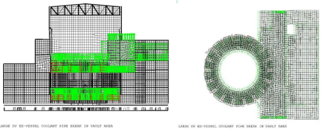
The selected load cases considered as significant actions for this preliminary structural assessment comprise gravity loads, seismic loads, internal pressure and vacuum loads (LOCA and LOVA, Fig 3), aircraft impact and external explosions (Fig. 4).
General elevation view Local plan view
External explosion Aircraft impact - Scenarios 1 to 5 (out of 13) Fig. 4: Accidental loads cases
Structural assessment and strength checks
The structural assessment on whether design margins were high enough or not has been based on methodologies which vary depending on the structural part to be considered. Specific tools have been developed in most of the cases to further process the internal forces resulting from the load combinations studied in the FE model. For the capacity checks of the elastomeric bearings, the internal forces computed at each pad for each load combination (one vertical force, two horizontal forces along global X and Y axes, and two rocking moments) have been computed and transferred to feed the checking procedure, which has been established in accordance to the provisions given in Refs. [0] and [0]. The following conditions have been considered: total distortion, rotational limitation, buckling stability and thickness of reinforcing plates.
For the strength checks of the 1D elements representing beams and columns in the FE model, the built-in procedure within CivilFEM v11.0 (Ref. [0]) has been followed for every load combination considered. This procedure is in accordance to the provisions given in EC 2 (Ref. [0]). Basically, two major checks have been carried out: axial load and biaxial bending, and shear.
For the set of shell (2D) elements representing shear walls and slabs, the checking methodology under combined in-plane and out-of-in-plane loading is based on the division of the shell cross section in three single layers, according to the provisions given by the Model Code (Ref. [0]). The shear forces are assumed to be taken by the core or central layer, whereas the membrane forces and the moments are assigned to the outer layers. Following the EC 2 and the Model Code, an approximation of the 75 percent of the element thickness is adopted for the internal lever arm. This methodology has been implemented in an in-house internal routine coupled with ANSYS
Floor response spectra
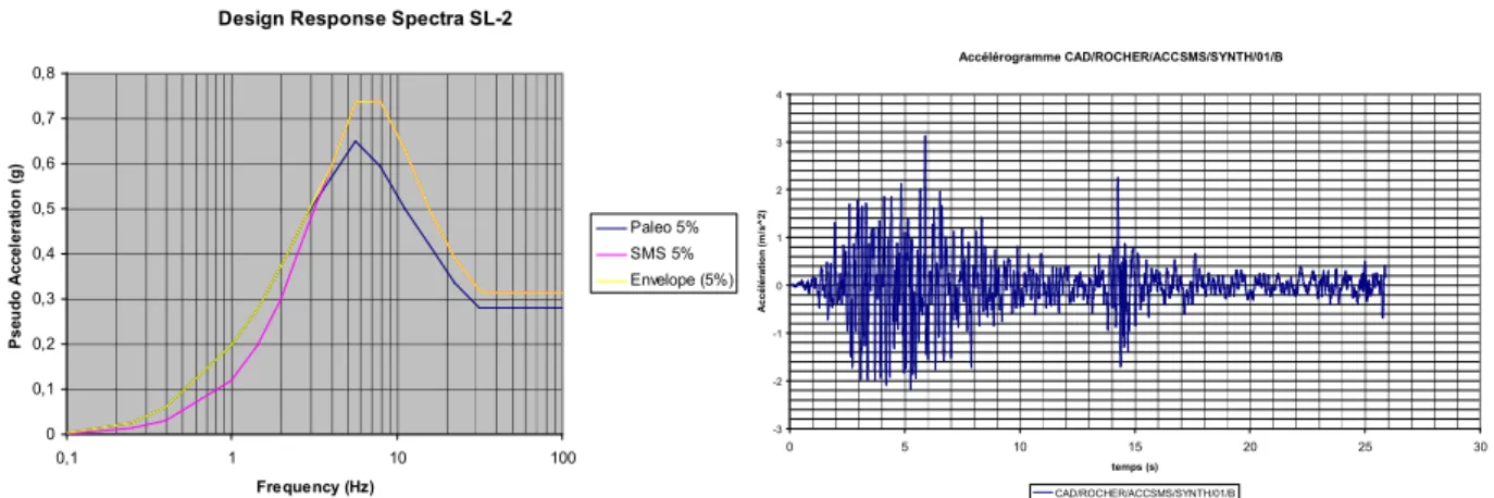
The calculation of the floor response spectra in the three global directions (X, Y, and Z) caused by seismic actions has been extended to a total number of 6 representative seismic loads scenarios at 26 different locations within the building. The design earthquake for ITER, called Safe Shutdown Earthquake or SSE, is defined as the envelope of two earthquakes: the “Seisme Majore de Securite” (SMS – Magnitude 5.8 at 7.1km) and the paleo-earthquake (Magnitude 7.0 at 18.5 km), defined for the conditions of the site of Cadarache. The SMS response spectrum envelops the Paleo response spectrum for frequencies above 3.5 Hz, approximately. Below this frequency, spectral ordinates are higher for the Paleo spectrum (Fig. 5). Six accelerograms representative of the design spectra have been made available by CEA to perform the time-history analysis.
The dynamic calculations preformed to obtain the absolute acceleration time histories at the monitoring location points, have been based on the “mode superposition based dynamic analysis” technique. A modal base up to 20 Hz has been adopted in the analyses, since this was shown to accurately represent the dynamic response of the structure. The damping ratio for the dynamic calculation has been preliminarily considered to be constant for all modes and equal to 5%. Modal composite damping is currently being implemented in the new analyses. The equations of motion are integrated in time using the implicit HHT algorithm, with a time step equal to 10-3 seconds.
The implementation of the artificial accelerations at the ground level in ANSYS has been achieved by rigidly attaching all the nodes representing soil impedance by means of Multi Point Constraint elements to a relatively big
point mass (107 times the mass of the whole Tokamak Complex) that has the three rotational degrees of freedom constrained. A load time history can then be applied in the three global directions whose values are Fi(t) = m•ai(t),
where m is the value of the point mass associated with the artificial node; ai(t) is the artificial accelerogram history
that is to be imposed in each direction i=X,Y,Z: and t is the time. This methodology ensures that the base motion exactly follows the input time history accelerations and that absolute (not relative) accelerations are computed at the desired locations. The methodology also allows imposing a rocking seismic motion at the base of the building.
RESULTS
Capacity checks and structural behaviour
Capacity checks according to the procedures outlined before have been carried for a representative selection of structural parts. Safety factor contours have then been obtained, where structural capacities could be easily displayed. Fig. 6 shows the corresponding safety factors computed in a certain load combination for the top reinforcement at the basemat, and the compressive strength of the concrete for the walls enclosing the Tokamak building (it is important to note that the ratio shown expresses demand/capacity and, therefore, the safe region lies in the range [0.0 / 1.0]).
Design Response Spectra SL-2
0 0,1 0,2 0,3 0,4 0,5 0,6 0,7 0,8
0,1 1 10 100
Frequency (Hz) P s e u d o A c c e le ra ti o n ( g ) Paleo 5% SMS 5% Envelope (5%) Accélérogramme CAD/ROCHER/ACCSMS/SYNTH/01/B -3 -2 -1 0 1 2 3 4
0 5 10 15 20 25 30
temps (s) A c c é lé ra ti o n ( m /s ^ 2 ) CAD/ROCHER/ACCSMS/SYNTH/01/B
Fig. 5: Design response spectra SL-2 (horizontal movement) and representative artificial signal
Basemat - Top reinforcement Tokamak bldg external walls- Compressive strength Fig. 6: Examples of computed safety factors
The distribution of load among the seismic isolators has also been given special consideration. Fig. 7 shows how the global vertical load of the Tokamak Complex is distributed among the pads for a characteristic gravity case. The different colours applied to each isolator correspond to the vertical load carried by the isolator compared to the average value. Red and blue ranges indicate more and less severely loaded isolators, respectively.
-40 -30 -20 -10 0 10 20 30 40 50
-80 -60 -40 -20 0 20 40 60 80
>120% >110% >100% >90% >80% >70%
Fig. 7: Gravity load distribution among the seismic pads Optimization proposals
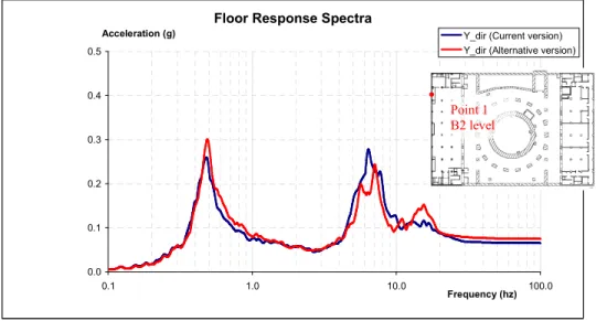
From the analyses performed a number of proposals for optimization have been derived and some of them have been implemented in a new version of the FE model. These proposals mainly affect the dimensions of the most relevant structural parts, such as the basemat or the thicker load carrying vertical walls. The feasibility of such proposals has been further investigated by studying the effect of these changes in the capacity and the overall response of the system. Fig. 8 shows the effect on the horizontal floor response spectrum at a particular location within the building, of the changes proposed (black line: initial design; red line: after implementation of changes in the FE mode). On Fig.8, note also the second peak which can have unexpected amplitudes. Sensitivity analyses have allowed to well understand this peak is generated by the rocking eigenmodes excited by the vertical seismic motion. This phenomenon is due to the non symmetry of the building and the fact the aseismic pads are not “dynamically equilibrated” although their design makes the structure statically equilibrated.
Floor Response Spectra
0.0 0.1 0.2 0.3 0.4 0.5
0.1 1.0 10.0 100.0
Frequency (hz)
Acceleration (g) Y_dir (Current version)
Y_dir (Alternative version)
Fig. 8: Comparison between horizontal floor response spectrum after implementation of changes
EFFECT OF THE SEISMIC WAVES PATTERN ONTO THE SEISMIC RESPONSE
The 500 neoprene pads supporting ITER Tokamak complex will provide a good isolation against horizontal ground movements, but not against vertical or rocking movements. Therefore, non-vertically incident waves,
Point 1 B2 level
Rayleigh waves or more generally the spatial incoherency of the seismic motion might have some significant contribution to the response of the structure. This contribution could be missed if the common assumption of vertically propagating waves is used in the soil structure interaction (SSI) analyses. In addition, the Tokamak complex is embedded almost 20 m in rock. Normally, the embedment of the foundation will produce some reduction in the seismic input to the building, when compared with the control point input defined at the ground surface. This effect of kinematic interaction due to the embedment of the foundation can also be significant. In this context, the work described in the present paper has been carried out to assess the differences in structural response at the Tokamak Complex that can derive from different assumptions about the seismic wave patterns (vertically incident waves, inclined waves, Rayleigh waves). Additionally, the effect of foundation embedment on the seismic input actually seen by the building has been investigated. Finally studies with a spatial incoherency model of the seismic input have been launched in order to have a model closer to the complex reality far away from a mono dimensional incident wave.
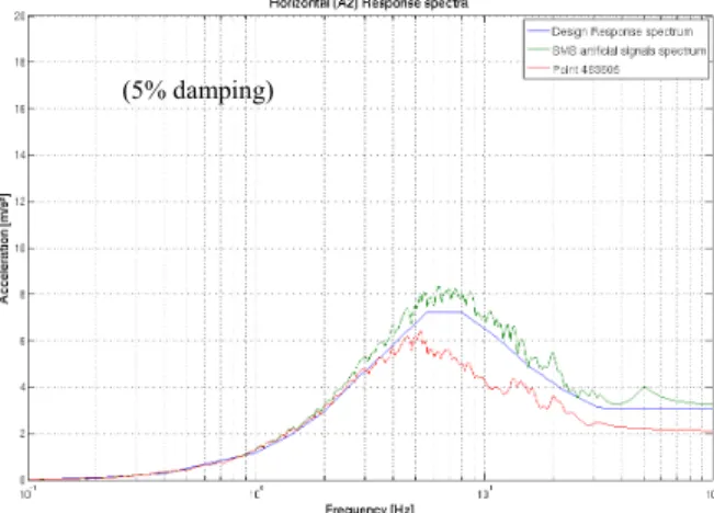
Analyses in which only the seismic pit is present, without the Tokamak complex building, show a significant reduction of the horizontal motion at the basemat level, when compared with motion of the control point at the surface. Fig. 9 shows that horizontal peak acceleration at the centre of the basemat (“Zero Period Acceleration” - ZPA of the spectrum) is in the order of 0.22 g, that is, 70% of the peak ground acceleration at the control point located at the surface of the rock. Spectral ordinates are also significantly lower than those at the design spectrum for frequencies above 4 Hz. The green line corresponds to the spectrum at the control point obtained in free field conditions, using the same input of acceleration time histories at the boundaries.
On the other hand, the effect of the embedment in the vertical motion is small. The response spectra of vertical motion at different points of the seismic pit, at different heights, show very minor differences with respect to the response spectrum of vertical motion at the control point.
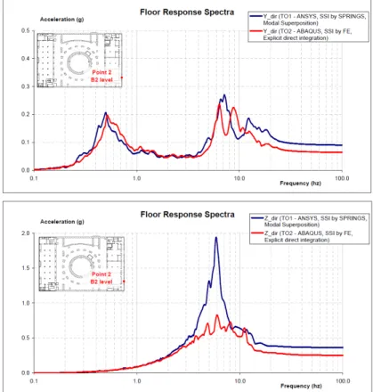
Fig. 10 gives the response spectra computed using a conventional distributed impedance approach, without considering the embedment effects (blue lines), compared with the spectra computed in the present study (red lines). Note the reduction at ZPA level in the horizontal response when the embedment is considered. Note also the reduction in the peak of the vertical spectrum, which is attributed to radiation damping in the Soil Structure interaction.
Fig. 9: Response spectra of horizontal motion at centre of seismic pit basemat (5% damping)
Fig. 10: Response spectra at concrete slab just above the neoprene isolation pads CONCLUSION
The structural design of the Tokamak Complex has been extensively reviewed by means of a consistent set of analyses based on the results obtained from a new FE model of the whole structure. The analyses have identified potential optimisation strategies whose feasibility has been further studied and confirmed.
The results show that the design margins of the initial design are high, therefore giving room for optimization. The changes proposed have been shown to be feasible, actually improving the structural response in some cases, and allowing for a further reduction of the structural mass which could, in turn, result in a lighter design of the seismic isolation system. Several of these proposals have been implemented for the final design.
Extensive seismic analyses with different models and assumptions have also been performed in order to determine the margins related to the earthquake hazards and well determine the parameters with the major influence onto the seismic response. The influence of Soil-Structure Interaction has been confirmed although the structure is seismically isolated.
REFERENCES
[1] ANSYS v11.0. User’s Manual.
[2] ASCE 4-98. “Seismic Analysis of Safety-Related Nuclear Structures”. American Society of Civil Engineers. 2000.
[3] NF EN 1337-3: “Structural bearings - Part 3. Elastomeric bearings". Noviembre 2005 (Spanish version). [4] prEN 15129:2007: “Anti-seismic devices". Draft. April 2007.
[5] CivilFEM Documentation Release 11.0.
[6] European Committee for Standardization. prEN 1992-1-1:2003. Eurocode 2, Design of Concrete Structures, Part 1: General Rules and Rules for Buildings. Revised final draft, Brussels, Belgium, December 2003.
[7] “Structural concrete. Textbook on behaviour, design and performance. Updated knowledge of the CEB/FIP Model Code 1990”. Volume 2: basis of design. 2nd, Corr. ed. FIB Bulletin 2. Lausanne: FIB.
Vertical - 5% damping Horizontal NS - 5% damping