306
Energy Generation by Suspension System
Ravindra Bhoite1, Somanath Jadhav2, Akshay Jape3, Vikram Phadatare4, Amardip Jadhav51, 2,3,4,5Department of Mechanical Engineering, SIETC, Paniv, Maharashtra, India.
Abstract
Regenerative Shock absorber is a type of suspension system that converts parasitic intermittent linear motion and vibration into useful energy, such as electricity. Conventional shock absorbers simply dissipate this energy as heat.
In our project, we used shock absorber, rack & pinion arrangement and dynamo. As shock absorber effect formed, spring is compressed and linear movement of rack is converted in rotary motion due to pinion moves as the rack is meshed with pinion. And the pinion is mounted on the shaft which is connected to shaft of dynamo. Due to this arrangement, rotary motion of pinion is used to rotate dynamo. As dynamo rotation leads to generation of energy. And this energy is energy is used to charge the battery and this stored energy is used for different vehicle accessories like power window, lights and air conditioner etc.This energy is applicable in most of the military vehicles, race automobile and maximum suspension systems. Keywords: Energy Generation, Suspension
System
1. INTRODUCTION
Fossil fuels are being consumed with very fast rate. Also the cost of fuel is increasing with a very fast rate. So somebody has to work on saving of the fuel consumption.Our aim is to demonstrate how the kinetic energy from the suspension of a car can be utilized to achieve our goal of obtaining maximum energy that would otherwise have gone waste.
We propose a design plan that converts the mechanical energy in cars to electrical energy much more efficiently than it has been done before. The electricity generated will then be used to recharge the car battery for further use for functioning of the car.There is a wide scope for regeneration of energy like regeneration of breaking systematic. We have decided to work on utilization of suspending mass of a vehicle through regeneration system with the help of shock absorber.Shock
absorbersare having reciprocating motion in it. Although the reciprocating distance is very low the suspending mass is very high i.e. the mass of total vehicle. When vehicle is on a normal road then also shock absorbers are working due to uneven roads, sudden breaking or sudden acceleration. So this reciprocating motion of shock absorbers can be converted into rotary motion and through small gearbox attached to alternator of automobile, electricity will be generated when shock absorbers will be reciprocating.
2. Literature Review
The purpose of this literature review is to go through the main topics of interest. The literature reviews is concerned with design of spur gear, DC generator, design of shaft, selection of bearings & shock absorber with theoretical and experimental evaluation. 1. Zhongjie Li, Lei Zuo*, JianKuang, and George Luhrs , This paper deal with energy-harvesting shock absorber is able to recover the energy otherwise dissipated in the suspension vibration while simultaneously suppress the vibration induced by road roughness.It can work as a controllable damper as well as an energy generator. The key component is a unique motion mechanism, which we called “mechanical motion rectifier (MMR)”, to convert the oscillatory vibration into unidirectional rotation of the generator. 2. Pei Sheng Zhang 2010“Design of Electromagnetic Shock Absorbers for Energy Harvesting from Vehicle Suspensions”, This paper discussed about the different type of suspension system. Also the rank and pinion arrangement in vehicle suspension.
IJISET - International Journal of Innovative Science, Engineering & Technology, Vol. 2 Issue 5, May 2015. www.ijiset.com
ISSN 2348 – 7968
307
that produce alternating current (AC) are called alternators. The device described in this paper is a generator capable of supplying an electrical load with the desired type of current: alternating current or direct
4. Rahul UttamraoPatil, Dr. S. S. Gawade,
“Design and static magnetic analysis of electromagnetic regenerative shock absorber”
Electronic equipment systems are precision system. There are some vibrations and impact in moving vehicles for road environments. Therefore, shock absorber is significant in protection of electronic equipment in moving vehicles. In this paper a systematic investigation to design or evaluation of a shock absorber for protection of electronic equipment system in harsh vibration-impact environment.
3. Working
In this project we have to develop a suspension energy generation unit by using rack and pinion method. It is less costly than the hydraulic unit.
Part of the system: A] Std. Part 1. Suspension unit 2. Rack and pinion 3. Generator.
B] Manufacturing part: 1. Chassis.
2. Drive to run generator (gear box)
Here, when the suspension works, the rack is set moving in a reciprocating motion. Due to this, the pinion starts rotating. The rotation ofthe pinion is then amplifiedinto rotation of a higher rpm by using the gear box. At the end of gear box we have attached the generator which generates the electricity.
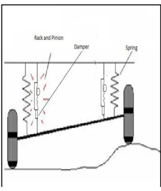
Fig .1 Working System
The above figure shows the implementation of the project and its working therein. As the vehicle passes over an uneven road surface, there is relative motion of the individual wheels.
As shown, the linear motion of the wheels causes the suspension to compress and this imparts motion to the rack which is attached to the wheel assembly. This in turn gives rotational motion to the pinion as shown in the highlighted area.
pr di an 3. ge th el re ex th lo co to F This is roject.The ab imensional mo nd completed s
.1 DC Genera The m ears is transmi he bearing a
lectricity. The everses the arm
xternal circuit. hat the polarity oop reverses.
ommutator cha o a pulsating dc
ig. 2 Structure of P
the final work bove diagram
odel of the pro state.
ator
motion of the itted to DC G and DC gen
commutator mature loop co
This occurs at y of the voltage
Through th anges the gene c voltage.
Fig. 3 Dynamom Prototype
king model of t shows the oject in worki
rack and pini Generator throu nerator gener
mechanica onnections to t t the same insta e in the armatu his process t
erated ac volta
meter the 3 ing ion ugh rate ally the ant ure the age 3.2 bri rec vo tap sec tha
4.
4. Fo he A)2 Full Wave B In man idge rectifier (F ctifier produc oltage as
ppedtransforme condary voltag The adv at no Centre-ta
Fig. 4 F
Design and
1 Design of sp or suspension
lical spring. ) By Assumin
F=Load on t C= spring in G= Modulus N/mm2
τ = Permissi N/mm2
Fi
Bridge Rectif ny power supp Figure 17) is u ces almostdou
a full w er rectifier u ge.
vantage of usin apped transform
Full Wave Bridge w
d Fabricatio
pring system we a
ng
the System = 4 ndex= 14
s of rigidity= 8
ible shear stres
ig. 5Spring Nomen
30
fier
ply circuits, th used. The bridg uble the outp
wave Centr using the sam
ng this circuit mer is required
wave rectifier
on
are selected th
425N
81370
s = 420
IJISET - International Journal of Innovative Science, Engineering & Technology, Vol. 2 Issue 5, May 2015. www.ijiset.com
ISSN 2348 – 7968
309
Wahl factor
Kw = .
= .
= 1.1016
1)
τ =³×KW
But C = Dm/d Dm=C×d
τ =
² ×KW
d2 = ×KW
= . ×KW
= 6.3 ≈ 6 mm
Wire Diameter = d= 6 mm Mean diameter =Dm=C.d= 84 mm Outer diameter = D0=Dm+d= 90 mm
Inner diameter = Di=Dm-d= 78 mm
Assuming Maximum deflection of the spring is 20 mm
δ = ³
⁴
But Dm=C. d
There for,
δ = ²
20 = ² N = 13 coils
Number of active coils is 13. Spring is plain grounded N=Nt=13
Solid Length = Nt× d = 78
Total gap= (Nt – 1) × gap between two adjacent coil
= 24 mm
Free Length (Lf) = Solid length + Total gap length + δ= 122 mm
Pitch of Coil = = 10.16
(Assuming gap between two adjacent coils is 0.5 to 2 mm under the maximum load.)
4.2 Design of Bearing
Axial Load= 945 N (assume acting on the single wheel)
Shaft Diameter= 15 mm
Bearing life for automobile cars= 50 million revolution
The relationship between the dynamic load, load carrying capacity equivalent dynamic load and bearing life is given by,
L10= (C/P)p
L10= rated bearing life (in million rev) C= dynamic load capacity (N) p = 3 (ball bearing)
C = P (L10)1/3
= 945 * (50)0.3 = 3480.9558 N ≈ 3500 N
From dimensions and static and dynamic load capacities of single-row deep groove ball bearing
For diameter of shaft 15mm and C= 3500 we get the diameter of Bearing is 32mm and C0 = static load capacity = 2500 N
4.3 Design of Gear Module m = 2
No. of teeth pinion = 14 No of teeth on rack = 38 dp = m×14 =28
Face width of pinion b = 2×m = 20 mm Power = 0.416 Kw
Speed assume np= 1440 rpm For cast iron material Sut = 410N/mm² Mt = ×106
= 2760.01 N-mm Lewis form factor is
Y = 0.289 for 14 teeth
Cs = service factor = 2 (for heavy load) Cv=
And v ³
= 2.11 ≈ 3 Cv = 0.5
Pt = 2Mt/dp
= 2×2760.01/28 = 197.14N Peff = ∗ = 2×197.14/0.5 = 788.56 N Beam Strength- Sb = mbσby
σb = Sut =
310
= 1579.91N
Factor of safety f(s) = Sb/Peff
= 1579.91/788.56
= 2.01 Wear Strength- Sw = bQdpK = 20 × QdpK Q =
= 1.46 K = 0.16( ) 2
BHN = 270 for cast iron material K = 1.17
Sw= 20×1.46×28×1.17 = 956.59 N
Factor of Safety f’(s) =
= 956.59/788.56
= 1.21
S
pecification
Material= Cast iron
No of teeth= 14
Module = 2
Diameter = 30 mm
Bore diameter = 15 mm
Face width= 20 mm
5. Manufacturing Process
Main body holder is a mild steel square pipe of 20x20cm², it is been cut, for the size of 600 mm(6nos.) and 450mm(4nos.) Such square pipe is cut and the corner cutting is done to facilitate the joining at corners by welding to make the frame of rectangular size.
Table 1: Frame manufacturing processes
Sr.
No. Process Machine Tool
1 Cutting of square pipe
Cutting
machine Cutting tool
2 Welding of base firm
Welding machine
Arc Welding
3
Cutting pipe for pillar
Cutting
machine Cutting tool
4 Welding for pillar
Welding machine
Arc Welding
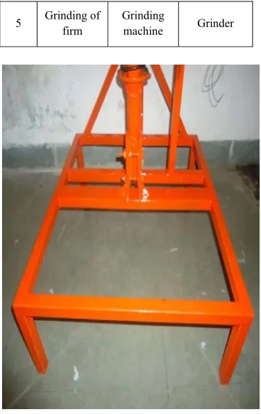
5 Grinding of firm
Grinding
machine Grinder
Fig.6 Base frame
6. Result and Conclusion
We are taken the reading for different number of teeth of gear.
Table 2: Readings
Sr. No.
No of teeth on pinion gear
Voltage (Volt)
Current (Ampere) 1 14 7.00 0.10 2 18 5.00 0.09
Vehicle Suspension Energy Generation is very efficient and useful in converting the Kinetic Energy from the movement of the vehicle, especially the suspension, which usually goes waste, to electric energy that can be used to fulfill needs of the auxiliaries in the vehicle.
IJISET - International Journal of Innovative Science, Engineering & Technology, Vol. 2 Issue 5, May 2015. www.ijiset.com
ISSN 2348 – 7968
311
this consumption is found to be 4% of total consumption. By newly designed suspension, regeneration system presently using alternator is detached from the engine and attached to the suspension system.
If we install this regeneration system for all 4 wheels then we can generate high amount of electric power. This high amount of electric power can be used for the working of car air conditioner or refrigeration system of vehicles. This suspension system will be mostly useful for heavy compressed vehicles, milk trucks, fire brigade trucks and also those having high requirement of electricity inside it. From result table we are observed that for a small number of teeth of gear we get the maximum voltage and current.
7. References
[1] Zhang Jin-qiu, PengZhi-zhao*, Zhang Lei, Zhang Yu,“A Review on Energy-Regenerative Suspension Systems for Vehicles”, WCE 2013, July 3 - 5, 2013, London, U.K.
[2] Rahul Uttamrao Patil, Dr. S. S. Gawade,“Design and static magnetic analysis of electromagnetic regenerative shock absorber”
[3] Zhongjie Li, Lei Zuo*, JianKuang, and George Luhrs ,Department of Mechanical Engineering, State University of New York at Stony Brook, Stony Brook, NY, 11794
[4] Pedro Portela, JaaoSepulveda, Joao SenaEsteves, “Alternating current and Direct current Generator”, Sep 3, 2008