Optimization of Process Parameter for Surface Roughness in
Drilling of Spheroidal Graphite (SG 500/7) Material
Prashant Chavan1, Sagar Jadhav2
Department of Mechanical Engineering,
Adarsh Institute of Technology and Research Center, Vita, Dist- Sangli, India.
Abstract
Using optimization techniques we can obtain better results in manufacturing industries. In today’s competitiveness market, company wants best quality products with minimum rejection and in minimum time of production. So all companies faces the problem of selecting the optimal input cutting parameters for machining operation to increase the quality of product. This experimental work represented on an optimization of process parameter for surface roughness in drilling operation of spheroidal graphite 500/7 material by applying Taguchi method of optimization. The spindle speed, feed rate and cutting tool material have been considered as cutting parameters for experiment. To achieve minimum surface roughness we have selected proper combination of spindle speed, feed rate and tool material.
Keywords: Optimization Technique, VMC machine, SG 500/7 material, Three types of cutting tools, Taguchi method.
1. Introduction
Hole making requiring specialized techniques to achieve best cutting condition. The quality and productivity are equally important in the analysis of drilling parameters. The roughness of drilled surfaces depends on the input conditions, material of the work piece or tool and condition of the machine tool. This study has indicated that for VMC drilling process Taguchi method is the most efficient method. Drilling can be described as a process where a multi-point tool is used to remove unwanted materials to produce a desired hole. It is therefore, essential to optimize quality and productivity simultaneously. Productivity can be understood in terms of material removal rate in the machining operation and quality represents satisfactory in terms of product characteristics as desired by the customers. There are number of research papers related to drilling, reaming and boring. In most of these research works carried out, material removal rate (MRR) and surface roughness are selected as objective functions. Furthermore, optimum values for input parameters such as speed, feed are calculated to obtain maximum MRR and minimum surface roughness value. The other feature governing drilling systems is quality of design. The quality of design can be improved through improving the value and yield in company-wide activities. Optimization is a technique through which better results are obtained under certain
conditions. For investigation, Spheroidal Graphite 500/7 material plate is considered as work piece and spindle speed, feed rate & HSS (High Speed Steel), uncoated carbide & Tin coated Carbide has been used as cutting tool. This work exposes that spindle speed has the most significant contribution on the metal removal rate among all the three parameters.
2. Problem Definitions
While doing this experimental work in SHREE VYANKATESHWARA METALLIKS Pvt. Ltd., it is observed that the produced parts under the drilling process have high rejection because of surface roughness in drilled hole. There is a rejection of 8 parts out of 100 parts because of surface roughness in drilled hole. So there is need to reduce the rejection ratio to avoid huge loss to company because of high machining cost, high labor cost, high tooling cost and, etc. The defective part will creates problems like wear out, leakage, difficulty in assembling and surface friction. So we tried to solve the problem of high surface roughness using robust design methodology. We identified three factors with three levels and experiment is carried out using L9 orthogonal array. The data obtained is analyzed using manual method. This methodology can be used for process improvement of similar kind.
3. Taguchi Approach
www.ijiset.com
noise (S/N) ratio to measure the quality characteristics different from the desired values. Usually, there are three categories of quality characteristics in the analysis of the S/N ratio, i.e., the – lower – better, the – higher – better, and the – nominal – better. The S/N ratio for each level of process parameter is compared based on the S/N ratio analysis. Regardless of the category of the quality characteristic, a smaller S/N ratio corresponds to better quality characteristics. The optimal combination of the process parameters can be predicted. Finally, a confirmation experiment is conducted to verify the optimal process parameters obtained from the parameter design. The formula for Smaller-The-Better signal to noise ratio is designed so that an experimenter can always select the smallest S/N ratio value to optimize the quality characteristic of an experiment. Smaller-The-Better, S/N ratio is determined by following equations:
S/N = -10 log10
For the smaller surface roughness, the solution is “Smaller-The-Better”. Where, S/N = Signal to Noise Ratio, n = No. of Measurements, y = Measured Value of surface roughness. The influence of each control factor can be more clearly presented with response graphs. Optimal cutting conditions of control factors can be very easily determined from S/N response graphs, too.
4. Surface Roughness Measurements
Portable surface roughness tester instrument is widely used to measure the surface roughness. A profile measurement device is usually based on a tangible measurement principle. The surface is measured by moving a stylus across the surface. As the stylus moves up and down along the surface, a transducer converts these movements into a signal which is then transformed into a roughness number and usually a visually displayed profile.
4.1 Arithmetic Surface Roughness Average (Ra)
Arithmeticalmean deviation from the mean life of profile is the average value of the ordinates (y1, y2…) from the mean line is Ra (Roughness average) value.
5. Design of Experiment
5.1 Work piece Material
The selected work piece material for investigation was Spheroidal Graphite 500/7. The chemical compositions are shown in Table 1. In chemical composition percentage of different composition is shown also various properties like mechanical properties shown in table 2.
Table 1: Chemical Composition of Spheroidal Graphite
C% Si% Mn% P% S% Mg% Cu%
3.20-3.60
2.30-2.90
0.4-0.6
0.03-0.06
0.02-0.040
0.030-0.055 <0.4
Table 2: Mechanical Properties of SG
Grade Tensile Strength
Yield Strength
Elong
ation Hardness
SG 500 MPa 320 MPa 7% 170~230 BHN
5.2 Cutting Tool Material
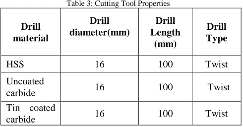
165 drilling experiment is carried out with vertical machining center under dry cutting conditions. Three different cutting tool materials, which were HSS, Tin coated carbide and uncoated carbide, are used. The materials and Specifications of the cutting tools are listed in Table 3.
Table 3: Cutting Tool Properties
Drill material
Drill diameter(mm)
Drill Length
(mm)
Drill Type
HSS 16 100 Twist
Uncoated
carbide 16 100 Twist
Tin coated
carbide 16 100 Twist
5.3 Selection of Parameters for Experimentation
According to various authors from literature review it is clear that Taguchi method is best to determine the main effects, significant factors and optimum machining conditions to obtain better performance characteristics, speed, feed, and tool material contribute the most in deciding surface roughness. Hence in a study of process parameter optimization of drilling process, we have selected speed, feed and tool material as factors for experimentation.
5.4 Experimental Plan
cutting parameters, three different speeds 850, 1150 and 1440 rpm. With three different feed rates 90, 120 and 135 mm/min. are used to carry out the tests. The vertical machining center machine is used for experiment.
5.5 Instrumentation
1) Surface roughness tester
Mitutoyo Portable Surface Roughness Tester that is equipped with a display unit, which provides Ip53 protection and offers optimum resistance to dripping water and dust. Integrated with a built-in-battery, it is capable of 500 measurements in a stretch when fully charged. We also provide a convenient carrying case for protecting the instrument when in the field. Moreover, it also has in-built memory that is capable of saving up to 10 measurements. The technical specifications of this tester are as follows:
i. Traversing direction: Backward detector
ii. Detecting method: Skid measurement
iii. Stylus tip: Diamond, 90°/5µmr
iv. Skid radius of curvature: 40mm
5.6 Designing Experiments
Three factors and three levels have been selected for experimental work which is shown in below table.
Table 4: Table indicating different levels of parameters
Factor Level
I II III
Speed 600 1130 1450
Feed rate 50 123 130
Tool
material HSS
Uncoated carbide
Tin coated carbide
5.7 Orthogonal Arrays (OA)
To select an appropriate orthogonal array for experiments, the total degrees of freedom need to be computed. The degrees of freedom are defined as the number of comparisons between process parameters that need to be made to determine which level is better and specifically how much better it is. For example, a three-level process parameter counts for two degrees of freedom. The degrees of freedom related with interaction between two process
parameters are given by the product of the degrees of freedom for the two process parameters. Once the degrees of freedom required are known, the next step is to select an appropriate orthogonal array to fit the specific task. Minimum number of experiment is calculated as,
Minimum number of experiments= [(L-1) x P] +1 Where,
L- Number of level of parameters=3 P- Number of parameters=3
Minimum number of experiment= [(3-1) x3] +1= 7
Therefore L9 orthogonal array has been used. Experimental design usually involves trying to optimizing a process which involve several factors at several levels
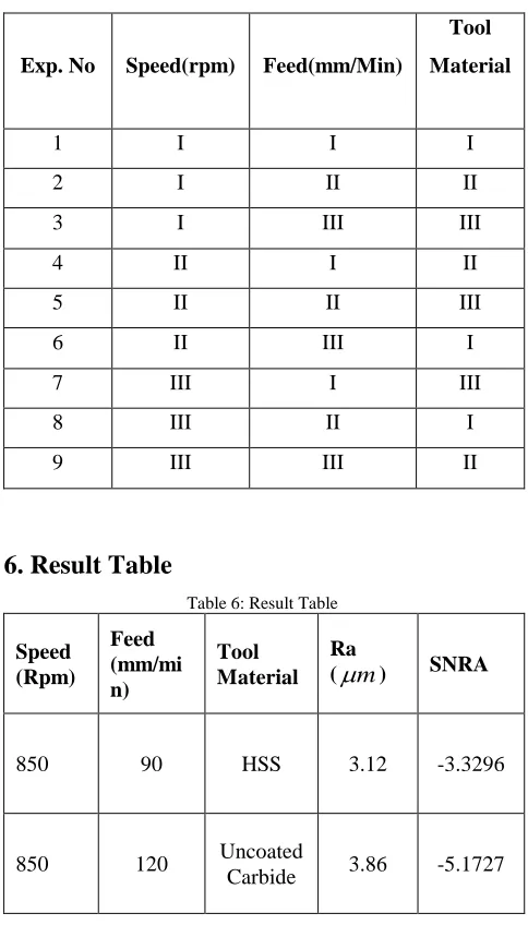
Table 5: Table indicating proposed orthogonal array
Exp. No Speed(rpm) Feed(mm/Min)
Tool Material
1 I I I
2 I II II
3 I III III
4 II I II
5 II II III
6 II III I
7 III I III
8 III II I
9 III III II
6. Result Table
Table 6: Result Table
Speed (Rpm)
Feed (mm/mi n)
Tool Material
Ra
(
µ
m
) SNRA850 90 HSS 3.12 -3.3296
850 120 Uncoated
www.ijiset.com
850 135
Tin Coated Carbide
3.14 -3.3685
1150 90 Uncoated
Carbide 3.20 -3.5349
1150 120
Tin Coated Carbide
3.06 -3.1647
1150 135 HSS 5.17 -7.6886
1440 90
Tin Coated Carbide
3.25 -3.6742
1440 120 HSS 4.79 -12.1012
1440 135 Uncoated
Carbide 2.83 -2.4618
6.2 Response Tables
Table 7: Response Table for HSS Tool
Tool Material
Process Parameter
S/N Ratio Rank Spindle
Speed
Feed Rate
HSS
850 90 -3.3296 1
1150 135 -7.6886 2
1440 120 -12.1012 3
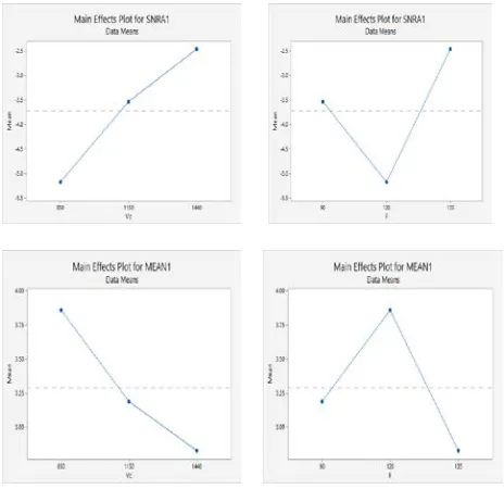
The mean S/N graph for surface roughness is shown in fig as mean effect plot.
Fig 1 Mean Effect Plot for S/N Ratio and Surface Roughness for HSS.
Table 8: Response Table for Uncoated Carbide Tool
Tool Material
Process Parameter
S/N
Ratio Rank Spindle
Speed
Feed Rate
Uncoated Carbide
850 120 -5.1727 3
1150 90 -3.5349 2
1440 135 -2.4618 1
The mean S/N graph for surface roughness is shown in fig as mean effect plot.
Table 9: Response Table for Tin coated Carbide Tool
Tool Material
Process Parameter
S/N Ratio Rank Spindle
Speed
Feed Rate
Tin Coated Carbide
850 135 -3.3685 2
1150 120 -3.1647 1
1440 90 -3.6742 3
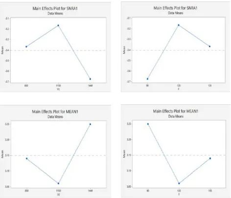
The mean S/N graph for surface roughness is shown in fig as mean effect plot
Fig. 3 Mean Effect Plot for S/N Ratio and Surface Roughness for Tin coated Carbide
7. Conclusions
The methodology of Taguchi’s robust design for Optimization of process parameters in drilling of SG 500/7 material is utilized. In this case we have taken orthogonal array & S/N ratio is into consideration from Taguchi’s optimization philosophy. In which reduction in Ra values is considered as main objective. For that purpose, drilling operation on SG 500/7 material carried out using HSS, Uncoated Carbide, Tin coated carbide tools. The conclusion related to predictive models is outlined.
The investigation follows the specific conclusion
1. In case of drilling operation using HSS tool material, it is found that the minimum surface roughness (Ra) value and optimum S/N ratio occurs when the cutting speed is 850 rpm & respective feed rate 90 mm/min.
2. In case of drilling operation using Uncoated Carbide tool material, it is found that the minimum surface roughness (Ra) value and optimum S/N ratio occurs when the cutting speed is 1440 rpm & respective feed rate 135 mm/min.
3. In case of drilling operation using Tin Coated Carbide tool material, it is found that the minimum surface roughness (Ra) value and optimum S/N ratio occurs when the cutting speed is 1150 rpm & respective feed rate 120 mm/min.
Appendix
Fig. 4 SG Plate Before Machining Fig. 5 SG Plate After Machining
Fig. 6 Surface Roughness Tester Fig. 7 Measurement Set up
Acknowledgments
The authors would like to present their sincere gratitude towards the faculty of Department of Mechanical Engineering, Adarsh Institute of Technology and Research Centre, Vita.
www.ijiset.com
References
[1] R. M. Galagali and Dr. R. G. Tikotkar, “Experimental investigations on wear process parameters optimization of Austempered Ductile Iron using Taguchi technique”, International Journal of Innovative Research in Science, Engineering and Technology,Volume 4, 2015, pp.2347-6760.
[2] H. Prakash , “An investigation to study the effect of drilling process parameters on surface finish using Taguchi method”, International journal of mechanical engineering and robotics research,Volume 3, 2014, pp.55-60.
[3] Md. Maksudul Islam, Sayed Shafayat Hossain and Md.Sajibul Alam Bhuyan, “Optimization of Metal Removal Rate for ASTM A48 Grey Cast Iron in Turning Operation Using Taguchi Method”, International Journal of Materials Science and Engineering, Volume 3, 2015, pp.134-146.
[4] A. Sreenivasulu Reddy, G. Vijaya kumar and C.Thirupathaiah, “Influence of The Cutting Parameters On The Hole Diameter Accuracy And The Thrust Force In Drilling Of Aluminium Alloys”, International Journal of Innovative Research in Science, Engineering and Technology, Volume 3, 2013, pp.6442-6450.
[5] K. Lipin and Dr. P. Govindan, “A Review on Multi Objective
Optimization of Drilling Parameters Using Taguchi Methods”,AKGEC International Journal of Technology, Volume 4, 2013, pp.11-21.
[6] A. Taskesen and K. Kutukde, “Analysis and optimization of drilling parameters for tool wear and hole dimensional accuracy in B4C reinforced Al-alloy”, Transactions of non-ferrous metals society of china, Volume 23, 2013, pp.2524-2536.
[7] A. Navanth and T. Karthikeya Sharma, “A Study Of Taguchi Method Based Optimization Of Drilling Parameter In Dry Drilling Of Al 2014 Alloy At Low Speeds”, International Journal of Engineering Sciences & Emerging Technologies, Volume 6, 2013, pp.65-75.
[8] Musonda Emmanuel Kabaso and Chen Yongjie
“Optimization of Cutting parameters when Hard Turning Hardened 42CrMo4 steel using the Taguchi Method”, International Journal of Advanced Research, Volume 2, 2014, pp.911-923.