Abstract - A silicon oxynitride (SiON) guided film is used as multilayered waveguide and using transfer matrix method.We propose the application of waveguide as a TE-Pass polarizer and TM-Pass polarizer having a passband in the third optical communication window of 1550 nm. Polarizer is key component for devices which require a single polarization for their operation. Most of the polarizers use metal clad waveguides with proper thickness and refractive index of cover and substrate. Index Terms— Optical Polarizer, Multi-layered waveguide,
TE mode, TM mode, Silicon oxynitride
1. INTRODUCTION
Optical waveguide: An optical waveguide is a physical structure that guides electromagnetic waves in the optical spectrum. Common types of optical waveguides include optical fibre and rectangular waveguides.
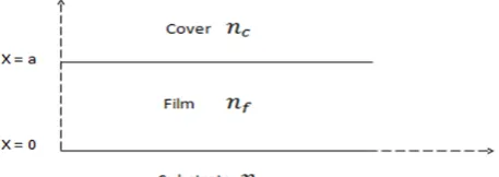
To fabricate a planer waveguide (Fig.1), usually a film (refractive index ), with a cover layer (refractive index
), is grown on a substrate (refractive index ) such that . Such waveguides are known as asymmetric waveguides. For symmetric waveguide, the cover and substrate are fabricated with same material and the refractive indices are equal, i.e. .
If there are more than one layer between Cover and Substrate, then such type of optical waveguides are known as Multilayer Waveguide.
In a multi-layered waveguide, we have choice to fabricate as many layers as we required. We can select the thickness of the layers and the type of the material according to our requirement.
Figure 1: Geometry of 3-layer waveguide structure
For a N-layer structure, the Define frame receives the vacuum wavelength, the refractive index values ns (substrate), n1, ... , nN(inner layers 1 to
N), nc (cover), and the thicknesses x1, ...
, xN of the inner layers. All dimensions are meant in
micrometers. The figure illustrates the relevant geometry:
Figure 2: Geometry of multilayer waveguide structure
Multilayer waveguides are used in the implementation of a variety of optical devices including semiconductor lasers, modulators, waveguide polarizer, Bragg reflectors, and directional couplers.
During the last twenty years, many attempts have been made to solve the wave equation [3] for the propagating modes in a general, lossless or lossy multilayer waveguide, in such a way as to facilitate the design and optimization of the above optical devices.
2. TE-PASS POLARIZER
Silicon oxynitride(SiON) planar waveguide structure can be fabricated by using plasma enhanced chemical vapour deposition (PECVD). In this technique oxidation reaction is initiated by plasma rather than using external heating source. Other techniques are melting technique, vapour phase deposition technique but CVD technique is superior. These waveguides find various applications in optical communication especially as wavelength filter, microresonator, modulator, polarization splitter and second harmonic generator .
A SiON guided film is used as multilayered waveguide and using transfer matrix method we propose the
Design of Single mode TE mode optical
Polarizer Using Silicon Oxynitide multilayed
waveguide
Sparsh Pratik1, Upendra Kumar2, Rajat Butola3
Electronics & Communication Department, Amity University Haryana
India
application of waveguide as a TE-Pass polarizer and TM-Pass polarizer having a passband in the third optical communication window of 1550 nm.[5] Polarizer is key component for devices which require a single polarization for their operation. Most of the polarizers use metal clad waveguides with proper thickness and refractive index of cover and substrate [9].
Multilayer waveguides are used in the implementation of a variety of optical devices including semiconductor lasers, modulators, waveguide polarisers, Bragg reflectors, and directional couplers.
We propose a multilayered SiON waveguide fabricated on substrate and has metalas cover is shown in fig 1. The choice of SiON is made for its highly desirable features such as low insertion loss, wide range of refractive index tailoring and realization of compact devices because of its low bending loss [4].The present configuration of optical polarizer will find applications in integrated optical circuits, signal processing from fiber optic sensors and fiber gyroscopes. For the analysis of the waveguide we have
used the transfer matrix formulation.
Figure 3: Geometry of TE-Pass Polarizer waveguide structur
= refractive index of the cover
= refractive index of the film i=1, 2………r = refractive index of the substrate
= thickness of the film layer in micron
2.1 Formulation
For
the calculation of propagation constant and resulting propagation mode profile of multi-layered waveguide, there are following methods:-1. Perturbation Method (4-layer) 2. Newton’s Method
3. Mode-matching method (5-layer structure) 4. Transfer Matrix Formulation
5. Argument Principle Method
The perturbation method for a lossless 5-layer structure, for a lossy 4-layer structure, and for a metal-clad waveguide was used to determine the propagation constants and the resulting propagating mode profiles. Newton’s method was used for metal-clad waveguides where the derivative of the dispersion equation can be obtained analytically [2]. A graphical method, as well as formal
as well as Newton’s method cannot easily be extended to multilayer structures, since their approach is analytic and the formulae involved become cumbersome [8].
None of the above methods can easily predict the number of propagating modes supported by the multilayer structure. This is a serious problem since there is no way of knowing when to stop searching for new propagating modes or even if the waveguide actually can support any mode at all. In fact, an additional analysis must be used to determine the number of guided modes before applying the zero-searching techniques. Even if the number of existing propagating guided modes is given, there is no guarantee that all the modes will be found [7]. All the above mentioned methods have serious problems in locating closely spaced roots. Moreover, all of them need an initial approximation closeto the actual zero. This initial estimate may be difficult to find, especially for high-loss propagating modes where the popular perturbation method does not apply. The method which we are using, is based on complex number theory. It is capable of finding the zeros or poles of any analytic function in the complex plane. The dispersion equation of a general multilayer waveguide is formed via the thin-film transfer-matrix theory. After its singularity points are identified, the complex plane is divided into regions where the dispersion equation is analytic, and all the zeros inside each region are found. In addition, the method provides the number of zeros or poles in each region. The transfer-matrix analysis provides an easy formulation of the multilayer structure problem. The method will be presented for TE modes but the extension to TM modes is straightforward [10].
A multilayer nonmagnetic slab waveguide structure (µ =
µo), is shown in Fig. 2. The refractive index, , of the ith
layer can be complex in general, i.e., , where
, is the extinction coefficient of the ith layer and i = 1.. . .
.r and r is the layer number. For a TE mode propagating in the + ̂direction in the ith layer, xi x xi 1 , the electric
field is exp ,and the magnetic
field in the same layer is
̂ exp where , , ̂
are the unit vectors in the x, y, z direction, respectively, is
the radian frequency, and is the complex
propagation constant with and the phase and the
attenuation constants respectively
2.2 TE Mode
A multilayer nonmagnetic slab waveguide structure (µ =
µo), is shown in Fig. 3. The refractive index, , of the ith
layer can be complex in general, [6] i.e., ,
where , is the extinction coefficient of the ith layer and i = 1.. . . .r and r is the layer number. For a TE mode propagating in the + ̂ direction in the ith layer, xi x
xi 1 , the electric field is exp
,and the magnetic field in the same layer is
̂ exp where , , ̂ are the
propagation constant with and the phase and the attenuation constants respectively
By using Maxwell’s differential equations, we get
̃
For TE mode,
= 0, only and components will present.
So by solving above two Maxwell’s equations, we get
1
2
̃
3
0
0
4
where is the freespace
permittivity, and 2 /
,c is thespeed of the light in the freespace and is the freespace wavelength. The electric and magnetic The Electric and Magnetic tangential fields within the ith layer are solutions of above equation, and can be written as
Ai
Bi
5a
j
5 b
When we apply boundary condition at
in equations
(5 a) and (5 b), then we will get
6
7
1 2 1
1 2
8
cos
9 a
9 b
Adding equation (9 a) and (9 b)
(10)
Utilizing the continuity of the tangential fields at any layer interface in the multilayer structure, the fields tangential to the boundaries at the top of the substrate layer , and at the bottom of the cover layer , , are related via the matrix product
… . .
11
Where
for i
1,2………..,r 12
Are the transfer matrices for all of the r layers having thickness . For propagating modes, the tangential fields at the boundaries must be exponentially decaying having the form
13
And
14
Where
,
0
From equation 11 , we get
0
The extinction ratio (PER) is defined as the ratio of power remaining (at the output end) [1] in the mode ( ) to the power remaining (at the output end) in the mode ( ), expressed in decibels. In addition, the insertion loss (PIL) is defined as the power loss associated with the
mode. Thus:
PER
= 10 log
PER
=
Loss in dB
−
Loss in dB
PIL
= 10log
(
)
PIL
=
Loss in dB
The above equations assume that the input mode has
unit power at the input end of the polarizer. In order to have a good TE-pass polarizer, we require the power remaining in the desired mode at the output end of the polarizer to be as high as possible. Hence a low value of PIL is desirable. The effectiveness of the polarizer in
discriminating against the passage of the mode
relative to the mode is measured by the PER parameter. Thus, this parameter should be as high as possible. Hence, we require a high PER and simultaneously a low PIL.
Figure 4: Effective index w.r.t.normalized film
Figure 5: Loss w.r.t.normalized film layer
Figure 6: Effective index w.r.t.normalized film layer
Figure 7: Loss w.r.t.normalized film layer
0
CONCLUSION
First of all, we have checked the function of TE mode by using transfer matrix method [2]. The value of phase constant and attenuation constant for 6-layer Lossy Dielectric Waveguide are available. The available data were calculated by the method of Argument Principle (APM).
Transfer Matrix method has been used to analyse a four layered waveguide consisting of SiON as guiding film. On this basis, we have designed TE pass polarizer. The range of SiON film thickness was estimated so that only the fundamental degenerate TE0 is supported. The calculations
showed that in the thickness range of 0.7µm -2.2 µm of SiON, the waveguide supports only TE0 mode.
In TE mode pass polarizer, the loss of TE mode is in the range of 0.2 – 2.5 dB/cm and for TM mode its range is 40 - 45 dB/cm, which quite higher in comparison to TE mode. So in this type of configuration of four layer waveguide, only TE mode will pass.
REFERENCES
[1] Vishnu Priye, Bishnu P.Pal, and K.Thyagarajan, “ Analysis and Design of a Novel Leaky YIG Film Guided Wave Optical Isolator,” J. Lightwave Technol., vol. 16, No.2, February 1998. [2] Anemogiannis and E.N.Glytis , “Multilayer waveguides: Efficient
numerical analysis of general structures,” J. Lightwave Technol., vol. 10, pp. 1344-1351, 1992
[3] M.Ajmal Khan and Hussain A. Jamid, “ TE/TM Pass Guided Wave Optical Polarizer”, IEEETEM2003
[4] H.Kogelnik, Theory of Optical Waveguides in Guided-wave Optoelectronics, T. Tamir,Ed. New York: Springer-verlag, 1988 [5] Ajoy Ghatak and K.Thyagarajan, “ Optical Electronics’’,
Cambridge University Press
[6] Joseph A Edminister and Vishnu Priye, “Electromagnetics Schaum’s Outline, Tata MacGraw Education Private Limited”.
[7] Ghamsari, B. G.; Majedi, A. H. “Rigorous Analysis of Superconducting Multilayer Optical Waveguides”, IEEE Transactions on Applied Superconductivity, vol. 17, issue 2, pp. 590-593, 2007.
[8] Emi Saitoh, Kunimasa Saitoh, and Masanori Koshiba “Compact TE/TM-pass Polarizer Based on LithiumNiobate on Insulator Ridge Waveguides” 2012 IEEE.
[9] David Jui-Yang Feng “Novel Integrated 2x2 TE/TM Polarization Controller on InGaAlAs-InP” 17th Opto-Electronics and Communications Conference (OECC 2012) Technical Digest, July 2012, Busan, Korea
[10] Emi Saitoh, Yuki Kawaguchi , “TE/TM-Pass Polarizer Based on Lithium Niobate on Insulator Ridge Waveguide” Volume 5, Number 2, April 2013.