GRADIENT IMAGE GENERATOR HARDWARE/SOFTWARE CO-DESIGN
ABBAS HAGHI
GRADIENT IMAGE GENERATOR HARDWARE/SOFTWARE CO-DESIGN
ABBAS HAGHI
A project report submitted in partial fulfilment of the requirements for the award of the degree of
Master of Engineering (Electrical - Computer and Microelectronic System)
Faculty of Electrical Engineering Universiti Teknologi Malaysia
iii
iv
ACKNOWLEDGEMENT
First and foremost, I would like to thank to my supervisor of this project, Dr. Muhammad Nadzir Marsono for his valuable guidance and advice. He inspired me greatly to work in this project. His willingness to motivate me contributed tremendously to my project.
Furthermore, I wish to express my gratitude towards my family especially my parents. There is no word I could write which is adequate to depict how much they mean to me. The reason that has been keeping me going on through these times.
Lastly, I must to thank to my friends and coursemates for their kind encouragement and constant support throughout the project.
v
ABSTRACT
vi
ABSTRAK
vii
TABLE OF CONTENTS
CHAPTER TITLE PAGE
DECLARATION ii
DEDICATION iii
ACKNOWLEDGEMENT iv
ABSTRACT v
ABSTRAK vi
TABLE OF CONTENTS vii
LIST OF TABLES x
LIST OF FIGURES xii
LIST OF ABBREVIATIONS xiv
LIST OF SYMBOLS xv
LIST OF APPENDICES xvi
1 INTRODUCTION 1
1.1 Background of the Study 1
1.2 Statement of the Problem 1
1.3 Objective of the Study 2
1.4 Scope of Work 2
1.5 Methodology 2
1.6 Report Outline 3
2 LITERATURE REVIEW 4
2.1 Smart Camera 4
2.1.1 Classification of Smart Cameras 5
2.1.2 Functionalities of ASIP 7
2.2 Canny Algorithm 7
2.2.1 Image Smoothing 9
2.2.2 Edge Detection 10
2.2.3 Directional Non-maximum Suppression
viii
2.2.4 Thresholding 15
2.3 Altera Cyclone II Board 16
2.3.1 DE2 Control Panel Facility 17
2.4 NTSC and PAL Standards 17
2.5 Bitmap Image 18
2.6 Motivation of Extended Work 18
3 MODIFIED CANNY ALGORITHM 22
3.1 Implementing RGB to GrayScale 22
3.2 Implementing Smoothing in Hardware 23
3.3 Computing Magnitude and Orientation of Gradient
of Image 25
3.4 Implementing Thinning in Hardware 29
3.5 Implementing Hysteresis 29
3.6 Chapter Summary 30
4 HARDWARE ARCHITECTURE 31
4.1 Chapter Summary 34
5 RESULTS AND DISCUSSION 35
5.1 Matlab Results 35
5.1.1 RGB to GrayScale 35
5.1.2 Smoothing 35
5.1.3 Magnitude and Direction of Gradient 38 5.1.4 Directional Non-maximum Suppression
(DNS) 38
5.1.5 Hysteresis 39
5.2 Co-Design Results 42
5.2.1 All Steps in NiosII 42
5.2.2 Computing only Grayscale in Hardware
and the Rest in NiosII 42
5.2.3 Computing only Smoothing in Hardware
and the Rest in NiosII 43
5.2.4 Computing only Magnitude and Direction
of Gradient and the Rest in NiosII 45 5.2.5 Only Thinning in Hardware and the Rest
ix
6 CONCLUSION 52
6.1 Future Works 53
x
LIST OF TABLES
TABLE NO. TITLE PAGE
2.1 Types of smart cameras, typical characteristics, and
sample applications. 5
2.2 Addresses of different information located in a bitmap
header file. 20
5.1 Execution time for every step of the canny algorithm in
software. 42
5.2 Execution time when only computing grayscale is in
hardware. 43
5.3 Numbers of SOPC builder generated module resources
when only computing grayscale is in hardware. 43 5.4 Numbers of computing grayscale designed module
resources. 43
5.5 Execution time when only smoothing in hardware using
method1. 44
5.6 Execution time when only smoothing in hardware using
method2. 44
5.7 Numbers of SOPC builder generated module resources
when only smoothing is in hardware. 45
5.8 Numbers of smoothing designed module resources. 45 5.9 Execution time when only computing gradient is in
hardware. 45
5.10 Numbers of SOPC builder generated module resources
when only computing gradient is in hardware. 46 5.11 Numbers of computing gradient designed module
resources. 46
5.12 Execution time when only thinning is in hardware. 46 5.13 Numbers of SOPC builder generated module resources
when only thinning is in hardware. 47
xi
5.15 Execution time for every step of the canny algorithm
implemented in hardware. 47
5.16 Execution time difference between hardware and
software of the canny algorithm. 48
5.17 Execution time when computing grayscale, smoothing
and computing gradient are in hardware. 48 5.18 Numbers of SOPC builder generated module resources
for final co-design. 48
5.19 Numbers of final co-design, designed module resources. 49
xii
LIST OF FIGURES
FIGURE NO. TITLE PAGE
1.1 Steps of implementing algorithms on hardware. 3
2.1 Functional structure of a smart camera. 4
2.2 Classification of smart cameras based on levels of
integration. 6
2.3 Canny algorithm steps. 9
2.4 Gaussian shape in respect to different standard
devia-tions. 10
2.5 Gaussian kernel. 10
2.6 Image results of a Gaussian function with different
standard derivations applied to an image. 10 2.7 Additive Gaussian noise applied to images of rows
number 2, 3 and 4 with a standard deviation of 0.1,1 and
10 , respectively. 11
2.8 Roberts, Prewitt and Sobel masks using for
implement-ing first order derivative inxandydirection. 13
2.9 An example of how gradient works. 14
2.10 An example of how thresholding works. 15
2.11 Altera DE2 development and education board. 16
2.12 The DE2 control panel concept. 17
2.13 Bitmap header file. 19
3.1 Gaussian function. 24
3.2 Graphical show of convolution an image with Gaussian
mask. 24
3.3 Sobel masks inxandydirections. 25
3.4 Central pixel and directions of it’s neighbors. 26 3.5 Division of trigonometric circle to four directions. 27
3.6 Upper half of trigonometric circle. 28
3.7 Black central pixel and its corresponding neighbors for
xiii
3.8 Black central pixel and its corresponding neighbors for
thresholding, based on the direction. 30 4.1 Sequence of canny algorithm implementation. 31
4.2 Hardware architecture of final design. 32
4.3 Sequence of passing data from one step to another one. 33 4.4 Sequence of input/output data to/from system. 34 5.1 Grayscale results using three different methods. 36
5.2 Smoothed results using Gaussian mask. 37
5.3 The measured bit difference between smoothed images
using original and estimated Gaussian mask. 37
5.4 Magnitude of gradient. 38
5.5 Simple thresholded and thinned image results
(T h=100). 39
5.6 A horizontal edge with 3 different values. 39 5.7 Image results before and after hysteresis (T h=200 and
T l=50). 40
5.8 Image results before and after hysteresis (T h=100 and
T l=50). 41
5.9 Matlab results of modified Canny algorithm. 41 5.10 A set of pixels; central pixels and corresponding
neighbors that should be send to hardware for
smoothing. 44
xiv
LIST OF ABBREVIATIONS
ASIC - Application Specific Integration Circuit ASIP - Application Specific Information Processing ATSC - Advanced Television Systems Committee
DAC - Digital to Analog Converter
DNS - Directional Non-maximum Suppression
DSP - Digital Signal Processor
FPGA - Field Programmable Gate Array
HD - High Definition
IP - Internet Protocol
LED - Light Emitting Diode
NTSC - National Television Standards Committee
PAL - Phase Alternating Line
PLD - Programmable Logic Device
RTL - Register Transfer Level
SDRAM - Synchronous Dynamic Random Access Memory SOPC - System on a Programmable Chip
SRAM - Static Random Access Memory
USB - Universal Serial Bus
xv
LIST OF SYMBOLS
T l – Low Threshold Value
T h – High Threshold Value
Hz – Hertz
M Bps – Megabytes Per Second M bps – Megabits Per Second
M – Mega
σ – Standard Derivative
CHAPTER 1
INTRODUCTION
1.1 Background of the Study
A new generation of cameras that have been appeared since the late 1990s is called smart cameras. A smart camera is not just a camera that take pictures but it can perform tasks and do some processing depending on situations. Motion detection, object measurement, read vehicle number plates and even recognizing human behavior are some examples of smart camera processing [1].
Based on the quality of a camera, the size of the frames is different. Large frame requires high bandwidth communication. The size of an 24bit uncompressed digital 720×480 NTSC (National Television Standards Committee) frame is about 8.3Mega bit per frame. For 30 frames per second, it is around 250Mega bit per second. Furthermore, it may not necessary to send all data of frame as some especial data of the image are sufficient. The gradient of an image can be used to extract important detail of the image [2]. If the 24bit image is binarized, a speed of 1.3MBps or 10.4Mbps for wireless image transfer is sufficient. Canny algorithm is one of the optimum methods to compute the gradient of an image [3].
1.2 Statement of the Problem
2
Achieving this level of processing power using programmable DSP (Digital Signal Processor) requires multiple processors. In order to efficiently use the hardware resources and increase the speed, hardware features like pipelining must be employed. A single FPGA (Field Programmable Gate Array) with an embedded soft processor can deliver the requisite level of computing power more cost-effectively, while simplifying board complexity [4].
1.3 Objective of the Study
The main objective of this project is to propose a software and hardware co-design architecture of Canny edge detection algorithm using FPGA for a fast image analysis. To achieve this aim, it is necessary to know the mathematical properties of edge detection. Therefore, the first objective of the project is to analyze the mathematical properties of Canny edge detection. The second objective is to map the mathematical operations as a hardware architecture model. Then several hardware/software Canny architectures are analyzed to evaluate each architecture trade-off. Finally execution time for every step in hardware and software compare together to determine which step should be done in software and which one is faster if implemented in hardware.
1.4 Scope of Work
The Modified Canny algorithm is benchmarked with a Matlab based implementation. The algorithm is simulated in Altera Quartus II and implemented in hardware to make a binary image of input image that contains just desired features, and has a less size in compare with original input image. The hardware architecture is based on RTL (Register Transfer Level) design methodology on Altera FPGA and input the image is a 24bit bitmap image.
1.5 Methodology
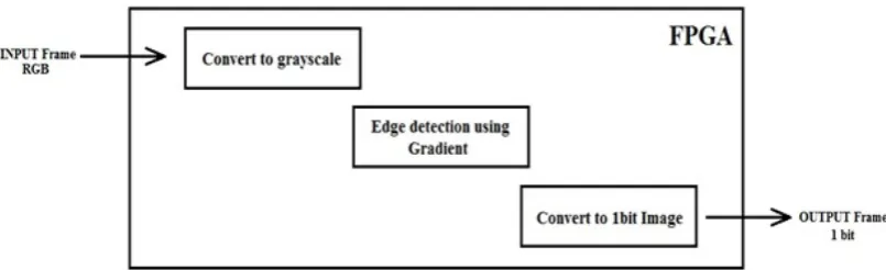
3
Figure 1.1: Steps of implementing algorithms on hardware.
gradient, in the next step the magnitude of first order derivative inxandy directions are computed using the Canny algorithm and are added together to yields gradient of the image. At last step the image is compressed as much as possible to get minimum size for a fast image transfer.
Canny algorithm step is written in Matlab (without modification). Some parts of Canny algorithm i.e. Arctan, are modified and compared with results from step 1. If the difference between results is negligible then modification is applied. The modified algorithm is written in NiossII Processor by Altera for various models of its FPGAs. execution time of every step is measured. Each processing step is separately analyzed as hardware structure. If the execution time is faster in software, the step is written in software else, it is implemented in hardware.
1.6 Report Outline
REFERENCES
1. Shi, Y. and Real, F. D. Smart Cameras: Fundamentals and Classification, Springer US, chap. 2. 2009, 19–34.
2. Chen, G. H., Yang, C. L. and Xie, S. L. Gradient-Based Structural Similarity for Image Quality Assessment. 2006 IEEE International Conference on Image Processing. 2006. 2929–2932.
3. Canny, J. A Computational Approach to Edge Detection. IEEE Transactions on Pattern Analysis and Machine Intelligence, 1986. 8(6): 679–698.
4. Neoh, H. S. and Hazanchuk, A. Adaptive Edge Detection for Real-Time Video Processing using FPGAs. Global Signal Processing Expo and Conference (GSPx 2004). 2004.
5. Real, F. D. and Berry, F. Smart Cameras: Technologies and Applications, Springer US, chap. 3. 2009, 35–50.
6. Shi, Y. and Lichman, S. Smart Cameras: A Review. Proceedings of 2005 Asia-Pacific Workshop on Visual Information Processing. 2005. 95–100.
7. Pflugfelder, R. and Micusik, B. Self-Calibrating Cameras in Video Surveillance, Springer US, chap. 9. 2009, 161–180.
8. Cavallaro, A. Change Detection for Object Segmentation, Springer US, chap. 10. 2009, 181–198.
9. Dominguez, G. F., Beleznai, C., Lizenberger, M. and Delbruck, T. Object Tracking on Embedded Hardware, Springer US, chap. 11. 2009, 199–223.
10. Wang, X. and Jin, J. Q. An Edge Detection Algorithm Based on Improved CANNY Operator. Seventh International Conference on Intelligent Systems Design and Applications (ISDA 2007). 2007. 623–628.
11. He, W. and Yuan, K. An Improved Canny Edge Detector and its Realization on FPGA. 2008. 6561–6564.
55
13. Zhao, H., Qin, G. and Wang, X. Improvement of canny algorithm based on pavement edge detection. 3rd International Congress on Image and Signal Processing. 2010. 964–967.
14. Rao, D. V. and Venkatesan, M. An efficient reconfigurable architecture and implementation of edge detection algorithm using Handle-C. International Conference on Information Technology: Coding and Computing (ITCC 2004). 2004. 843–847.
15. Gonzalez, R. C. and Woods, R. E. Digital Image Processing. 2nd ed. Prentice Hall. 2002.
16. DE2-70 DE2 Development and Education Board UserManual, 2007.
17. DE2 Development and Education Board UserManual, 2007. URL www.altera.com.
18. DE2 Development and Education Board UserManual, 2006. URL www.altera.com.
19. Keith, J. NTSC, PAL, and SECAM Overview, Newnes, chap. 8. 2007, 257 – 387.
20. Miano, J. Compressed Image File Formats : JPEG, PNG, GIF, XBM, BMP. Longman Pub Group. 1999.
21. Jack, K. YCbCr to RGB Considerations. Technical report. Intersil. 1997. 22. Rao, D. V., Pati, S., Babu, N. A. and Muthukumar, V. Implementation and
Evaluation of Image Processing Algorithms on Reconfigurable Architecture using C-based Hardware Descriptive Languages. International Journal of Theoretical and Applied Computer Sciences, 2006. 1(1): 9–34.