Development of OFDM based Cooperative
Communication System for Mitigation of
Effect of Carrier Frequency offset
Anil M. Jadhao
1, Dr. Ashok A. Ghatol
2Ph.D. Scholar, Department of Applied Electronics, Sant Gadge Baba Amravati University, Amravati, India1
Ex-Vice Chancellor, Dr. Babasaheb Ambedkar Technological University, Lonere, India 2
ABSTRACT: In this paper, the effect of carrier frequency offset on a network where multiple independent devices cooperate to form virtual multiple input multiple output networks is analyzed. The common phase error and inter-carrier interference effect on cooperative Alamouti STC OFDM system due to inter-carrier frequency offset is investigated and OFDM based cooperative communication system for mitigating the effect of carrier frequency offset is developed.
KEYWORDS: OFDM; MIMO; Frequency Offset; CPE; ICI; Cooperative Diversity; Cooperative Alamouti STC.
I. INTRODUCTION
Wireless communication is one of the most vibrant areas in the communication field today. It is used to transfer information over a distance without the use of a guided medium. Due to the sharply increasing in demand for wireless connectivity, it has developed extremely fast during the last two decades. However, wireless communication is not as reliable as guided medium communication, due to fading and other propagation effects. Accordingly, the techniques to improve its capacity and reliability become the key objective for current research. Numerous techniques have been proposed to enhance the performance and reduce the interference for wireless communication, such as Multiple-Input Multiple-Output (MIMO), Space-Time Codes (STCs) and Orthogonal Frequency Division Multiplexing (OFDM).
It is widely acknowledged that the combination of MIMO and STCs is able to provide a significant improvement of the capacity and bit error performance of wireless systems. However, there are some existing limitations of MIMO. For instance, transmitters/receivers may only be equipped with a single antenna due to their tiny physical size which does not facilitate the space of at least a half wavelength to install two uncorrelated transmit (Tx)/receive (Rx) antennas. Thus, cooperative communication technique has been introduced to allow single-antenna devices to cooperate and create a virtual (or distributed) MIMO system in such as a way that the STC and MIMO concepts can still be implemented.
OFDM is a technique to against the frequency-selective fading or narrowband interference in wireless communication, thus improving the system reliability. This technique allows data to be transmitted in parallel by modulating the data on a set of orthogonal sub-carriers. An analysis which could clearly point out when the application of cooperative communication to OFDM-based systems shall significantly improve the system bit error performance, compared to a SISO system, is highly desired.
Synchronization in OFDM systems has been the subject of much analysis [1; 3; 5; 6; 8; 9-12]. The commonly considered errors of symbol timing offset, sample rate offset, phase noise, and carrier frequency offset each present their own unique set of challenges. OFDM systems are particularly sensitive to errors in carrier frequency, a problem made worse by the high carrier frequencies and narrow sub-carrier spacing of many systems as well as the economic need to use low-cost oscillators [1; 3; 6; 11; 13]. WiMAX, for example, has a sub-carrier spacing of about 15 kHz and is licensed to operate at frequencies such as 3.5 GHz.
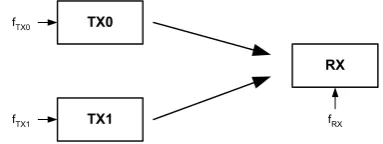
transmitter has its own independent clock, the received signal has two separate frequency offsets. In this scenario, even with perfect synchronization to one of the two transmitters, the receiver will still experience a frequency offset due to the second transmitter.
TX0
TX1
RX
fTX0
fTX1 fRX
Figure 1: Cooperative Alamouti STC OFDM system.
In this paper we explore the effect of carrier frequency offset and then consider the case of a cooperative Alamouti STC OFDM system.
II. RELATEDWORK
The primary effect of frequency offset is inter-carrier interference that leads to a reduction in SINR and ultimately to an irreducible error floor in performance was shown in [3]. As much effort has gone into quantifying the effects of carrier frequency offset, certainly more has been spent in mitigating its effects. [5], for instance, presents various such techniques.
The foundation of cooperative communication lies in the concept of relaying, introduced by [14]. Later on, information theoretic properties of relay channels have been studied in [15]. In these pioneering contributions, maximum achievable communication rate has been derived for a basic three terminal model, containing a source, a relay and a destination. The idea of user cooperation has been introduced by [16, 17] for uplink transmission that improves the capacity and lowers the outage probability for a given data rate. A cooperative protocol is designed where two cooperating partners listen to the broadcasted packet and retransmit the data for each other. This technique also helps in improving the diversity gain, as both transmitting nodes have uncorrelated channels with the destination. Later, [18] extended the concept of cooperation, by designing energy efficient multiple access protocols based on decode-and-forward (DF) and amplify-and-decode-and-forward (AF) relaying modes. Significant gains in terms of outage probability as compared to direct link transmission has been illustrated in this work. In addition to fixed relaying modes, an outage probability analysis in [19] has been carried out for adaptive and incremental redundancy modes. Distributed channel codes are used at relaying nodes for improving the bit or block error rate in [20–22]. A number of interesting relaying strategies including repetition coding [23–25], space time cooperation [26], and space time coded cooperation [27] have been proposed and significant gain in terms of error performance, outage probability and power efficiency has been illustrated.
III.OVERVIEW OF ANALYSIS OF CARRIER FREQUENCY OFFSET
Figure 2: Illustration of effect of frequency offset.
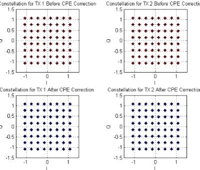
Figure 3: Constellations of Alamouti STC OFDM system with +/-3% frequency offset, 64-QAM, 40dB SNR in AWGN, before and after CPE correction. Black stars are original encoded constellation points.
Many studies, including [1; 9; 12], have investigated methods to correct OFDM ICI, but these techniques are beyond the scope of this paper.
As shown in [10] and [1], analysis of a received OFDM signal with frequency offset reveals these two effects. Given a sequence of N data symbols X[k], OFDM symbol time Ts, frequency error ferr in Hz, and phase offset , we represent the transmitted OFDM waveform in discrete time as
1 0 ) / ) ( 2 (1
0
,
]
[
]
[
N k N n T f k jN
n
e
k
X
n
s
err s (1) The signal s[n] is transmitted through a channel with impulse response h[n]. At the receiver, additive white Gaussian noise (AWGN) v[n] is added. We assume perfect time and phase synchronization. The resulting signal is then demodulated with a DFT, yielding
1 0 ) / 2 ( ] [ ] [ ] [ 1 ] [ N n N kn j e n v n h n s N kR
(2) To simplify analysis and separate the effects of fading from our investigation, we assume an AWGN channel where h[n] = [n]. Then
] [ ] [ 1 ] [ 1 0 1 0 / ) ( 2 k V e l x N k R N n N l l N k T f l n
j err s
(3) The case where l=k can be separated and R[k] re-written as]
[
]
[
]
0
[
]
[
]
[
k
X
k
I
I
k
V
k
R
(4)
Where V[k] is AWGN.
Further simplification of (3) when l=k yields the term I[0]:
formula s Euler' by , ) / sin( 2 ) sin( 2 1 1 expansion series geometric by , 1 1 1 1 1 ] 0 [ 1 1 / / / / 2 / 2 1 0 / 2 1 0 / 2
N T f j s err s err N T f j N T f j N T f j T f j T f j T f j N T f j N N T f j N n n N T f j N n N T nf j s err s err s err s err s err s err s err s err s err s err s err e N T f j T f j N e e e e e e N e e N e N e N I
j f T Ns err
s
err
e
err sN
T
f
N
T
f
I
1 1)
/
sin(
)
sin(
]
0
[
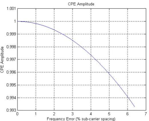
(5)Figure 5: CPE amplitude as a function of percent frequency error.
The first term of (4) is not unique to OFDM systems. X[k]I[0] would also be seen at the output of a matched filter in a single carrier system, yielding the same CPE. On the other hand, the second term of (4) is indeed a direct result of OFDM. It consists of the interfering contributions by all the other sub-carriers in the system. [1] writes this ICI term as
j l f T k Ns err
s err N
k l l
s err
e N k T f l N
k T f l l
X k
I
1 1 1
,
0 sin ( )/
) (
sin ] [ ]
[
(6) The degradation due to this ICI is approximated in [10] as
0 2
10 ln 3
10 ) (
N E f f dB
D err s
(7) Where f is the OFDM sub-carrier spacing in Hz, ferr is the frequency error (Hz), and Es/N0 is the linear SNR per
symbol.
IV.ANALYSIS OF COOPERATIVE ALAMOUTI STCOFDMSYSTEM
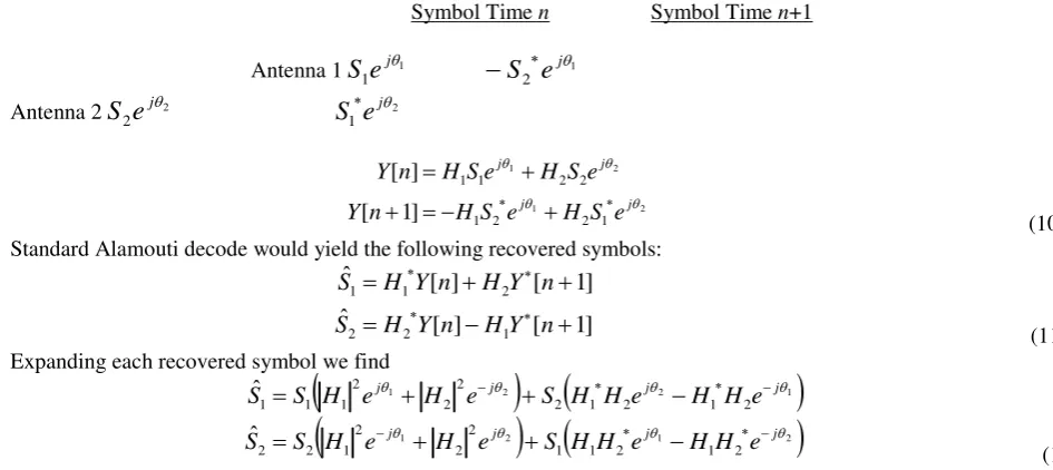
The Alamouti space-time code is a 2x1 transmit diversity scheme where, at symbol time n, antenna 1 transmits symbol S1 and antenna 2 transmits symbol S2 [2]. At symbol time n+1, antenna 1 transmits symbol –S2* and antenna 2
transmits symbol S1*.
Symbol Time n Symbol Time n+1
Antenna 1 S1-S2 *
Antenna 2 S2S1*
Thus the received signals are
1 2 2 1
2 2 1 1 ] 1 [
] [
S H S H n
Y
S H S H n Y
Where H1 and H2 are complex channel coefficients. The transmitted symbols can then be recovered, assuming perfect channel estimation: ] 1 [ ] [ ˆ ] 1 [ ] [ ˆ 1 2 2 2 1 1 n Y H n Y H S n Y H n Y H S (9) For an OFDM system, we can simply apply the Alamouti STC scheme to each OFDM sub-carrier symbol independently.
V. EFFECT OF CPE
In the case of cooperative communications, we have two independent sources of frequency offset, as illustrated in Figure 1. If we first consider the CPE, we find that we have a different CPE on each antenna due to the difference between the two transmitter frequencies and the receiver frequency:
Symbol Time n Symbol Time n+1
Antenna 1 1
1 j
e
S
1 2 je
S
Antenna 2 2
2 j
e
S
2 1 je
S
2 1 2 1 1 2 2 1 2 2 1 1 ] 1 [ ] [ j j j j e S H e S H n Y e S H e S H n Y (10) Standard Alamouti decode would yield the following recovered symbols:]
1
[
]
[
ˆ
]
1
[
]
[
ˆ
1 2 2 2 1 1
n
Y
H
n
Y
H
S
n
Y
H
n
Y
H
S
(11) Expanding each recovered symbol we find
1 2
1 2
1 2 2 1 2 1 2 1 1 2 2 2 1 2 2 2 1 2 1 2 2 2 2 1 1 1
ˆ
ˆ
j j j j j j j je
H
H
e
H
H
S
e
H
e
H
S
S
e
H
H
e
H
H
S
e
H
e
H
S
S
(12) Elimination of the CPE is traditionally performed with a single phase rotation. In this cooperative scenario, we see that this approach is non-optimal for all but the degenerate case where 1 = -2. Instead, as found in [8], the optimalapproach is to use two different CPE corrections, one per received symbol in time and introduced before Alamouti decoding: 1 2 2 1
]
1
[
]
[
ˆ
]
1
[
]
[
ˆ
1 2 2 2 1 1 j j j je
n
Y
H
e
n
Y
H
S
e
n
Y
H
e
n
Y
H
S
(13)We then find that the different CPEs have been eliminated from the recovered symbols:
2
2 2 1 2 ) ( 2 1 ) ( 2 1 1 ) ( 2 2 ) ( 2 1 2 2 2 2 2 1 1 ) ( 2 1 ) ( 2 1 2 ) ( 2 2 ) ( 2 1 1 1 2 1 2 1 2 2 1 1 1 2 1 2 2 2 1 1 ˆ ˆ H H S e H H e H H S e H e H S S H H S e H H e H H S e H e H S S j j j j j j j j (14)
VI.EFFECT OF ICI
We find that the effect on a cooperative Alamouti STC OFDM system due to ICI is little different than that to a standard OFDM system. We still apply (7) but now have a contribution from each of our two frequency offsets.
We model a channel gain imbalance as a transmit power imbalance subject to a total power constraint P. For linear powers PTX1 and PTX2 transmitted from antennas 1 and 2, respectively, and power imbalance P, we have:
P
P
P
TX1
TX2
Since
P
TX1
PP
TX2,
PP
TX2
P
TX2
P
Therefore
P
P
P
P
TX
1
1
and
P
P
P
TX
1
1
2 (15)We then have the total degradation in system performance given approximately by
)
,
(
)
,
(
)
(
err1 TX1 err2 TX2total
dB
D
f
P
D
f
P
D
(16)For our system with two different frequency errors (fTX1- fRX) and (fTX2 - fRX) and respective SNRs PTX1/(N0B) and PTX2/(
N0B), we hypothesize that the optimal receiver frequency fRX can be found by minimizing the sum of the individual degradations. Thus we set the derivative of the composite Dtotal to 0 and solve for fRX:
B N P f f f f B N P f f f f f B N P f f f B N P f f f dB D TX RX RX TX TX TX RX RX TX TX TX RX TX TX RX TX total 0 2 2 2 2 2 0 1 2 1 2 1 2 2 0 2 2 2 0 1 2 1 2 2 10 ln 3 10 10 ln 3 10 10 ln 3 10 ) (
2 2
2 2
010 ln 3 10 ) ( 0 2 2 0 1 1 2 2 B N P f f B N P f f f dB df dD TX RX TX TX RX TX RX
2 1 2 2 2 1 1 1 2 2 1 1 2 1 2 2 1 10
TX TX TX TX TX TX TX TX RX TX TX TX TX TX TX RX TX RX TX TX RX TXP
P
P
f
P
P
P
f
f
P
f
P
f
P
P
f
P
f
f
P
f
f
Substituting in (15),
P
f
P
P
f
f
RX TX TX
1
1
1
2 1 (17)Note that (17) provides the optimal receiver frequency assuming perfect knowledge of the transmit frequencies and channel powers. Under these same assumptions, a traditional (non-cooperative) system would have no frequency offset, and therefore no CPE or ICI and no performance degradation. Even with perfect knowledge, the cooperative system will experience a loss in performance so long as fTX1≠ fTX2 (and P ≠ 0, of course).
VII. SIMULATION OFCOOPERATIVE ALAMOUTI STCOFDMSYSTEM
worth noting that, under similar assumptions, the traditional non-cooperative system would have no degradation in performance.
We take parameters from the WiMAX 802.16-2004 standard [
7
]: 4MHz bandwidth, 256 sub-carriers (200 data, 55 guard, 0 at DC), and 15.625 kHz sub-carrier spacing.(A)GENERAL SYSTEM PERFORMANCE
Figure 6 shows basic BER performance with curves as expected from the analysis. With no frequency offset, the SISO and STC curves are the same and agree with the standard QAM BER formula [4, Eqn 6.23]. We note that we would only see diversity gain due to STC with a fading channel. With a frequency error of 1% of the sub-carrier spacing and equal STC branch power, we again see that curves for SISO, STC, and the performance degradation predicted by (7) and (16) all match. For STC, we set one transmitter to +1% frequency offset, the other transmitter to -1% frequency offset, and set the receiver to be the mean of the two transmit frequencies, which is the optimal setting for equal branch power, as given by (17). For purposes of comparison, we have intentionally not removed the 1% frequency offset in the SISO case, even though with perfect knowledge this removal would be possible. Finally, we show the effect of not correcting the CPE.
Figure 6: Top: BER performance for 64-QAM uncoded OFDM system. Bottom: zoom of top plot.
(B) PERFORMANCE WITH SUB-OPTIMAL CPECORRECTION
Figure 7 shows a plot of BER against receiver frequency and (single, non-optimal) CPE correction angle. In this scenario we step through various branch power imbalances and leave the transmit frequencies at +1% and -1% offsets. We then try various combinations of fRX and CPE angle. We observe that behavior is about as expected, with fRX shifting toward the stronger transmit frequency. As the SNR imbalance increases, the system degenerates to a SISO system. fRX approaches the dominant transmit frequency, the frequency error diminishes, and the CPE angle goes to 0.
Figure 7: 3D BER showing measured optimal fRX and CPE angle with increasing STC branch power imbalance.
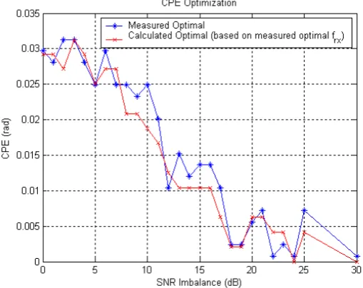
Figure 8: Optimal fRX vs measured optimal with nonoptimal CPE correction.
For a given fRX, we see in Figure 9 that the best single CPE we can choose is given by the argument of (
5
), with frequency error given by the difference between fRX and the dominant transmit frequency.Figure 9: Best possible single CPE angle correction.
Figure 10: Degeneration of STC to SISO with increasing SNR imbalance.
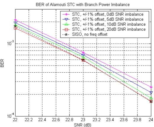
Finally, we observe that even with sub-optimal CPE correction, performance degradation due to frequency offset is due primarily to OFDM ICI. Figure 11 shows that a single-carrier STC system with various amounts of SNR imbalance, a +/-1% frequency offset, and a single non-optimal CPE correction performs roughly the same as a system with no frequency offset at all.
(C) PERFORMANCE WITH OPTIMAL CPECORRECTION
With optimal CPE correction given by (13), Figure 12, unlike Figure 8, shows a strong match between the predicted fRX given by (17) and the measured optimal.
Figure 12: Optimal fRX vs measured optimal with optimal CPE correction.
Further, the degeneration of STC to SISO in Figure 13, unlike in Figure 10, does not show any increase in BER between 0 and 5dB SNR imbalance, as there is no inter-STC symbol interference with optimal CPE correction. Figure 14 shows the degeneration of STC (with frequency offset) to SISO with no frequency offset on the standard BER vs SNR axes.
Figure 14: Degeneration of STC to SISO with increasing SNR imbalance.
VIII.CONCLUSIONS
We have shown that the primary effect of carrier frequency offset on a cooperative Alamouti STC OFDM system is OFDM ICI, a well-studied phenomenon with performance degradation given by (7) and (16). With perfect channel and frequency offset knowledge, we can completely eliminate the contribution due to CPE using (13). Unlike the non-cooperative SISO case, the receiver cannot eliminate the ICI even with perfect knowledge. However, the effect of ICI is no worse than that experienced by a regular SISO system with similar (albeit non-differential) frequency offset.
REFERENCES
[1] Abhayawardhana, V. and I. Wassell, “Residual Frequency Offset Correction for Coherently Modulated OFDM Systems in Wireless Communications,”Proc. IEEE Veh. Tech. Conf., pp. 777-781, May 2002.
[2] Alamouti, S., “A Simple Transmit Diversity Technique for Wireless Communications,”IEEE J. Sel. Areas Communications, pp. 1451-1458, October 1998.
[3] El-Tanany, M. S., Y. Wu, and L. Hazy, “OFDM Uplink for Interactive Broadband Wireless: Analysis and Simulation in the Presence of Carrier, Clock and Timing Error,”IEEE Trans. Broadcasting, pp. 3-19, March 2001.
[4] Goldsmith, A., Wireless Communications, Cambridge University Press, New York, 2005.
[5] Hanzo, L., M. Munster, B. J. Choi, and T. Keller, OFDM and MC-CDMA for Broadband Multi-User Communications, WLANs and Broadcasting, Wiley, West Sussex, England, 2003.
[6] Heiskala, J. and J. Terry, OFDM Wireless LANs: A Theoretical and Practical Guide, Sams, Indianapolis, IN, 2002. [7] IEEE Std 802.16-2004: IEEE Standard for Local and Metropolitan Area Networks, 2004.
[8] Mitran, P. and S. Sandhu, “On Phase Noise Compensation in STC-Encoded OFDM Systems,”IEEE Communications Letters, 2005. [9] Moose, P., “A Technique for Orthogonal Frequency Division Multiplexing Frequency Offset Correction,”IEEE Trans. Communications, pp.
2908-2914, October 1994.
[10] Pollet, T., M. van Bladel, and M. Moeneclaey, “BER Sensitivity of OFDM Systems to Carrier Frequency Offset and Wiener Phase Noise,” IEEE Trans. Communications, pp. 191-193, February-April 1995.
[11] van Nee, R. and R. Prasad, OFDM for Wireless Multimedia Communications, Artech, Boston, 2000.
[12] Zhao, Y. and S.-G. Haggman, “Intercarrier Interference Self-Cancellation Scheme for OFDM Mobile Communication Systems,”IEEE Trans. Communications, pp. 1185-1191, July 2001.
[13] Anil M. Jadhao & Ashok A. Ghatol, “Effect of Carrier Frequency Offset on Cooperative Alamouti STC OFDM Systems,” Journal IETE Technical Review Volume 25, 2008 - Issue 4, Pages 186-19.
[14] E. C. V. der Meulen, “Three Terminal Communication Channels,”Advanced AppliedProbability, vol. 3, pp. 120–154, 1971. (31)
[16] A. Sendonaris, E. Erkip, and B. Aazhang, “Increasing Uplink Capacity via User Cooperation Diversity,” in Proceedings of IEEE International Symposium on Information Theory (ISIT 1998), Cambridge, MA , USA, Aug 1998.
[17] A. Sendonaris, E. Erkip, and B. Aazhang, “User Cooperation Diversity Part I and Part II,”IEEE Transactions on Communications, vol. 51, no. 11, pp. 1927–38, Nov 2003.
[18] J. N. Laneman and G. W. Wornell, “Energy Efficient Antenna Sharing and Relaying for Wireless Networks,” in Proceedings of IEEE Wireless Communications and Networking Conference, WCNC. 2000, pp. 7–12.
[19] J. N. Laneman, D. N. C. Tse, and G. W. Wornell, “Cooperative Diversity in Wireless Networks: Efficient Protocols and Outage Behavior,” IEEE Transactions on Information Theory, vol. 50, no. 12, pp. 3062–3080, 2004.
[20] B. Zhao and M. C. Valenti, “Distributed Turbo Coded Diversity for the Relay Channel,”Electronic Letters, 2003, vol. 39, pp. 786–787, 2003. [21] Y. Cao and B. Vojcic, “Cooperative Coding using Serial Concatenated Convolutional Codes,” in Proceedings of IEEE Wireless
Communications and Networking Conference (WCNC), Mar 2005.
[22] A. Chakrabarti, A. de Baynast, A. Sabharwal, and B. Aazhang, “LDPC Code Design for Half-Duplex Decode and Forward Relaying,” in Proceedings of 43rd Allerton Conf. on Communication, Control, and Computing, Sept. 2005.
[23] A. Nosratinia, T. E. Hunter, and A. Hedayat, “Cooperative Communication in Wireless Networks,”IEEE Communications Magazine, vol. 42, no. 10, pp. 74–80, Oct 2004.
[24] A. Nosratinia and T. E. Hunter, “Cooperative Diversity through Coding,” in Proceedings of IEEE ISIT, Laussane, Switzerland.Jul 2002, p. 220. [25] A. Nosratinia and T. E. Hunter, “Diversity through Coded Cooperation,”IEEE Transactions on Wireless Communications, vol. 5, no. 2, pp.
283–289, Feb 2006.
[26] J. N. Laneman and G. W. Wornell, “Distributed Space Time Coded Protocols for Exploiting Cooperative Diversity in Wireless Networks,” IEEE Transactions on Information Theory, vol. 49, no. 10, pp. 2415–2425, 2003.