ISSN(Online): 2320-9801 ISSN (Print): 2320-9798
I
nternational
J
ournal of
I
nnovative
R
esearch in
C
omputer
and
C
ommunication
E
ngineering
(An ISO 3297: 2007 Certified Organization) Website:
www.ijircce.com
Vol. 5, Issue 1, January 2017
Review on Stability Mid-point of Transmission
Line using STATCOM
Ishant Shrivastava1, Hitesh Kumar Lade2
M. Tech. Scholar, Dept. of EE, Surbhi College of Engineering and Technology, Bhopal, India1
Head of Department, Dept. of EE, Surbhi College of Engineering and Technology, Bhopal, India2
ABSTRACT: Regarding the power system large wind farms are greatly affected stability and control issues. So it
requires a deep study to overcome this potential problems and it requires advanced control and compensating devices to avoid & recover large disturbances this paper involve the use of Static Synchronous Compensator (STATCOM) for stabilizing the grid voltage after grid-side disturbances such as a three phase short circuit fault, temporary trip of a wind turbine and sudden load changes. These will help to maintain and regulate the proper voltage. The DC voltage at individual wind turbine (WT) inverters is also stabilized to facilitate continuous operation of wind turbines during disturbances.
KEYWORDS: STATCOM, Dynamic Compensator, SVC, Transient Stability, V-Q Response.
I. INTRODUCTION
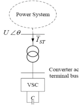
STATCOM is basically a voltage source converter, VSC that converts a dc voltage at its input terminals into three-phase ac voltages at fundamental frequency of controlled magnitude and three-phase angle. VSCs use pulse width modulation, PWM, technology, which makes it capable of providing high quality ac output voltage to the grid or even to a passive load (Uzunovic, 2001). STATCOM provides shunt compensation in a similar way as SVC but utilizes a voltage source converter rather shunt capacitors and reactors (Machowski, 1997). The basic principle of operation of a STATCOM is the generation of a controllable AC voltage source behind a transformer leakage reactance by a voltage source converter connected to a DC capacitor. The voltage difference across the reactance produces active and reactive power exchanges between the STATCOM and the power system (Wang and Li, 2000). The effect of stabilizing controls on STATCOM controllers have been investigated also in several recent reporting (Wang and Li, 2000), (Wang, 1999).
Recent development of power electronics introduces the use of FACTS devices in power systems. FACTS devices are capable of controlling the network condition in a very fast manner and this unique feature of FACTS devices can be exploited to improve the transient stability of a system. Reactive power compensation is an important issue in electrical power systems and shunt FACTS devices play an important role in controlling the reactive power flow to the power network and hence the system voltage fluctuations and transient stability. The flexible AC transmission system (FACTS) are now recognized as a viable solution for controlling transmission voltage, power flow, dynamic response ,etc. and represent a new era for transmission systems. It uses high-current power electronic devices to control the voltage, power flow, etc. of a transmission system.
ISSN(Online): 2320-9801 ISSN (Print): 2320-9798
I
nternational
J
ournal of
I
nnovative
R
esearch in
C
omputer
and
C
ommunication
E
ngineering
(An ISO 3297: 2007 Certified Organization) Website:
www.ijircce.com
Vol. 5, Issue 1, January 2017
is considered, the results may deviate significantly from those found for the simplified model. The primary objective of our project is to find the maximum power and the corresponding location of the shunt FACTS devices when the actual line model is considered. Based on the simplified line model it has been proved that the centre or midpoint of a transmission line is the optimal location for shunt FACTS devices. When the actual model of the line is considered, it is found that the FACTS device needs to be placed slightly off-centre to get the highest possible benefit.
Figure 1: Line diagram of STATCOM
II. FEATURE OF STATCOM
A STATCOM has both turn-on and turn-off control capability (IGBTs).
It generates an output ac voltage from a dc voltage.
The ac voltage is controllable both in magnitude and phase angle.
Flexible Alternating Current Transmission Systems (FACTS) devices, namely STATIC synchronous Compensator (STATCOM), Static Synchronous Series Compensator (SSSC) and Unified Power Flow Controller (UPFC), are used to control the power flow through an electrical transmission line connecting various generators and loads at its sending and receiving ends. FACTS devices consist of a solid-state voltage source inverter with several Gate Turn off (GTO) thyristor switch-based valves and a DC link capacitor, a magnetic circuit, and a controller. The quality of AC waveforms generated by the FACTS devices depends on the valves and the various configuration magnetic circuits. The inverter configuration used in this paper can be utilized to build a voltage source inverter.
III. BASIC CONFIGURATION OF STATCOM
ISSN(Online): 2320-9801 ISSN (Print): 2320-9798
I
nternational
J
ournal of
I
nnovative
R
esearch in
C
omputer
and
C
ommunication
E
ngineering
(An ISO 3297: 2007 Certified Organization) Website:
www.ijircce.com
Vol. 5, Issue 1, January 2017
to realize a voltage sourced converter for power utility application and it is based on harmonics and loss considerations, pulse width modulation (PWM) or multiple converters are used. Inherently, STATCOMs have a symmetrical rating with respect to inductive and capacitive reactive power. For example, the rating can be 100 MVAR inductive and 100 MVAR capacitive. For asymmetric rating, STATCOMs need a complementary reactive power source. Figure 6 shows Static Synchronous Compensator (STATCOM) used for midpoint voltage regulation on a 500-kV transmission line.
Figure 2: Schematic Diagram of STATCOM
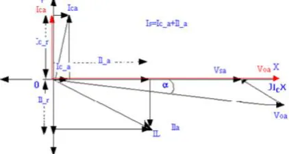
Figure 3: Phasor diagram for inductive load operation
ISSN(Online): 2320-9801 ISSN (Print): 2320-9798
I
nternational
J
ournal of
I
nnovative
R
esearch in
C
omputer
and
C
ommunication
E
ngineering
(An ISO 3297: 2007 Certified Organization) Website:
www.ijircce.com
Vol. 5, Issue 1, January 2017
IV. MODELING OF THE STATCOM AND ANALYSIS
The fundamental phasor diagram of the STATCOM terminal voltage with the voltage at PCC for an inductive load in operation, neglecting the harmonic content in the STATCOM terminal voltage, is shown in figure 7. Ideally, increasing the amplitude of the STATCOM terminal voltage Voa above the amplitude of the utility voltage Vsa causes leading (capacitive) current Ic to be injected into the system at PCC. Iac, the real component of Ic, accounts for the losses in the resistance of the inductor coil and the power electronic converter. Ideally, if the system losses can be minimized to zero, Ic_a, would become zero, and Ic would be leading at perfect quadrature. Then, Voa , which is lagging and greater than Vsa , would also be in phase with Vsa. The STATCOM in such a case operates in capacitive mode (when the load is inductive).
Figure 4: Vref signal (dotted lines) along with the measured positive-sequence voltage vm at the STATCOM
We will now verify the dynamic response of our model. Open the STATCOM dialog box and select "Display Control parameters". Verify that the "Mode of operation" is set to "Voltage regulation" and that "External control of reference voltage Vref" is selected. Also, the "droop" parameter should be set to 0.03 and the "Vac Regulator Gains" to 5 (proportional gain Kp) and 1000 (integral gain Ki). Close the STATCOM dialog block and open the "Step Vref" block (the red timer block connected to the "Vref" input of the STATCOM). This block should be programmed to modify the reference voltage Vref as follows: Initially Vref is set to 1 pu; at t=0.2 s, Vref is decreased to 0.97 pu; then at t=0.4 s, Vref is increased to 1.03; and finally at 0.6 s, Vref is set back to 1 pu. Also, make sure that the fault breaker at bus B1will not operate during the simulation (the parameters "Switching of phase A, B and C" should not be selected).
Figure 5: The reactive power generated (negative value) by the STATCOM
ISSN(Online): 2320-9801 ISSN (Print): 2320-9798
I
nternational
J
ournal of
I
nnovative
R
esearch in
C
omputer
and
C
ommunication
E
ngineering
(An ISO 3297: 2007 Certified Organization) Website:
www.ijircce.com
Vol. 5, Issue 1, January 2017
This time constant depends primarily on the power system strength at bus B2 and on the programmed Vac Regulator gains of the STATCOM. To see the impact of the regulator gains, multiply the two gains of the Vac Regulator Gains by two and rerun the simulation. You should observe a much faster response with a small overshoot.
Figure 6: Measured voltage Vm on both systems
We will now compare our STATCOM model with a SVC model having the same rating (+/- 100 MVA). If you double-click on the "SVC Power System" (the magenta block), you will see a SVC connected to a power grid similar to the power grid on which our STATCOM is connected. A remote fault will be simulated on both systems using a fault breaker in series with fault impedance. The value of the fault impedance has been programmed to produce 30% voltage sag at bus B2.Before running the simulation; you will first disable the "Step Vref" block by multiplying the time vector by 100. You will then program the fault breaker by selecting the parameters "Switching of phase A, B and C" and verify that the breaker is programmed (look at the "Transition times" parameter) to operate at t=0.2 s for a duration of 10 cycles. Check also that the fault breaker inside the "SVC Power System" has the same parameters. Finally, set the STATCOM droop back to its original value (0.03 pu).
V.CONCLUSIONANDFUTUREWORK
It is found that if STATCOM is installed at 250 km from sending end i.e. midpoint of the line, system becomes transiently stable as shown in the results. The study has shown that FACTS devices obtain maximum benefits from their stabilized voltage support when placed at the mid-point of the line. The mid-point siting is also most efficient in terms of control of reactive power. The transmission line must be operating under the thermal limit and the transient stability limit.
REFERENCES
1. Zhou, E.Z., 1993. “Application of static VAR compensators to Increase Power System Damping”, IEEE Transactions on power system, 8(2):655-661.
2. Wang, H.F. and F. Li, 2000. “Design of STATCOM Multivariable Sampled Regulator”, Int. conf. on Electric Utility Deregulation and power Tech, City University, London.
3. Hingorani, N.G. and L. Gyugyi, 1999. “Understanding FACTS”, IEEE Press, New York.
4. Hamad, A.E., 1986. “Analysis of Power System Stability Enhamsement by Static VAr Compensators”, IEEE Transactions on power Systems, 1(4): 222-227. 5. M. Sajedihir, Y. Hoseinpoor , P.Mosadegh Ardabili, T. Pirazadeh., 2011. “Analysis and Simulation of a STATCOM for Midpoint Voltage Regulation of
Transmission Lines”, Australian Journal of Basic and Applied Sciences, 5(10): 1157-1163.
6. S. T. Karris, “Introduction to Simulink with Engineering Applications”, Third Edition, Orchard Publications, Aug. 2011.
7. P. C. Krause, Oleg Wasynczuk and Scott D. Sudhoff, “Analysis of Electric Machinery”, Second Edition, IEEE Press, New York, 2004.
8. Sidhartha Panda and Ramnarayan N. Patel, “Improving Power System Transient Stability with an Off–Centre Location of Shunt FACTS Devices”, Journal of Electrical Engineering, Vol. 57, No. 6, pp. 365–368, Jun. 2006.
9. G. Sybille and P. Giroux, “Simulation of FACTS Controllers using the MATLAB Power System Blockset and Hypersim Real-Time Simulator”, IEEE PES, Panel Session Digital Simulation of FACTS and Custom-Power Controllers, Winter Meeting, New York , Jan. 2002.
10. Douglas J. Gotham, and G. T. Heydt, “Power Flow Control and Power Flow Studies for System with FACTS Devices”, IEEE Trans. on Power Systems, Vol. 13, No. 1, pp. 60-65, Feb. 1998.