ISSN(Online): 2320-9801
ISSN (Print): 2320-9798
I
nternational
J
ournal of
I
nnovative
R
esearch in
C
omputer
and
C
ommunication
E
ngineering
(An ISO 3297: 2007 Certified Organization)
Vol. 4, Issue 4, April 2016
Edge Truncated Suspended Rectangular
Microstrip Antenna
Suryakanth Nirate1, S.L.Mallikarjun2, R.M.Vani3, P.V.Hunagund4
Research Scholar, Dept. of Applied Electronics, Gulbarga University, Kalaburagi, Karnataka, India1 Guest faculty, Dept. of Applied Electronics, Gulbarga University, Kalaburagi, Karnataka, India2 Professor & Head, Univ. Sci. Inst. Centre (USIC), Gulbarga University, Kalaburagi, Karnataka, India3 Professor & Chairman, Dept. of Applied Electronics, Gulbarga University, Kalaburagi, Karnataka, India4
ABSTRACT: In this paper a design and development of Edge Truncated Suspended Rectangular Microstrip Antenna
(ETSRMSA) is presented. Here micro-strip patch antenna is designed to improve the bandwidth by edge truncating technique. The micro-strip patch antenna is very popular for its low profile, low cost, light weight, easy to feed, and their attractive application. The VSWR ≤ 2, the substrate material of FR-4 with relative permittivity 4.4 and loss tangent of 0.0245 is used in this proposed antenna. The Return loss, input impedance and VSWR have been measured by using Vector Network Analyser. Further antenna ETSRMSA gives the bandwidth of 27.84% and 47.86% respectively.
KEYWORDS: Edge Truncated Antenna, Suspended Microstrip antenna, Rectangular Patch antenna.
I. INTRODUCTION
Micro strip antenna is basically designed in such a way that an integration of two parallel conducting layers which is separated by a dielectric material is printed on to a single board. The lower layer and upper layers act as a ground plane and radiator respectively [1]. A simple patch antenna uses a patch of half wavelength long and having a larger ground plane which may increase the antenna size on the contrary gives better performance. We can design different shapes of micro strip patch elements such as dipole, triangular, rectangular, elliptical, and circular and square [3]. But we use rectangular microstrip for better radiation characteristics. Microstrip antennas are the successors of the printed antennas which are the present inventory for any type of wireless application with its frequency components sparing to different applications in defense, GPS, missile systems and satellite communications [2, 4].
Micro strip patch antenna contain a dielectric substrate on ground plane which is advantageous for configuration of low profile, low manufacturing cost ,less weight and is capable of integrate with micro wave integrated circuit technique. Not only in single frequency operation but also capable to operate in dual and triple frequency operation. Beside these advantages it has a major problem of narrow bandwidth which can be retrieved with several techniques like by increasing the thickness of substrate or modify by E shape and U slot patch antenna [5]. In this paper a design and development of Edge Truncated Suspended Rectangular Microstrip Antenna (ETSRMSA) is presented.
II. PROPOSED ANTENNA DESIGN
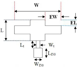
In the proposed design, the antenna has been designed for 6 GHz and is fed using microstrip line feed. The length and width of the rectangular patch are Land Wrespectively. The feed arrangement consists of quarter wave transformer of length Ltand width Wt which is connected as a matching network between the patch and the microstripline feed of
length Lf50 and width Wf50. At the very first the antenna is designed in a suspended mode. In the suspended rectangular
microstrip antenna configuration, two layers of FR4 substrates (εr = 4.4, h = 1.6 mm and tan δ=0.0245) separated by
ISSN(Online): 2320-9801
ISSN (Print): 2320-9798
I
nternational
J
ournal of
I
nnovative
R
esearch in
C
omputer
and
C
ommunication
E
ngineering
(An ISO 3297: 2007 Certified Organization)
Vol. 4, Issue 4, April 2016
Table.1 shows the dimensions of the proposed antenna.
Table 1: Dimensions of the Antenna
Parameter Value in mm
Length of the Patch(L) 10.38 Width of the Patch(W) 15.21
Lt 6.35
Wt 0.46
Lf50 6.29
Wf50 3.06
ISSN(Online): 2320-9801
ISSN (Print): 2320-9798
I
nternational
J
ournal of
I
nnovative
R
esearch in
C
omputer
and
C
ommunication
E
ngineering
(An ISO 3297: 2007 Certified Organization)
Vol. 4, Issue 4, April 2016
While truncating edge of the patch, antenna designed with air gap ()=0 mm [6] is considered. Fig.2. shows the top view geometry of ETSRMSA. On the top of four sides of the patch edge is truncated [7]. The truncated edge length
(EL) and edge width (EW) of the antenna are taken in terms of λ/20.66 mm and λ/9.59 mm respectively.
III.RESULTS AND DISCUSSION
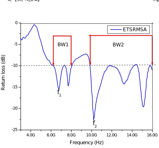
The antenna bandwidth over return loss less than -10 dB is measured experimentally on Vector Network Analyser (Rohde & Schwarz, Germany make ZVK model 1127.8651.60). The variation of return loss verses frequency of ETSRMSA is as shown in Fig. 3. From this graph the experimental bandwidth (BW) is calculated using the equations
BW= [ (f2 - f1)/fc]×100% ---eq. (1)
were, f1 and f2 are the lower and upper cut of frequencies of the band respectively when its return loss reaches – 10 dB
and fc is the center frequency of the operating band. i.e.
fc=[(f1+f2)/2] ---eq. (2)
Fig. 3 Variation of Return loss Verses Frequency of ETSRMSA
From this figure, it is clear that, the antenna operates between 3 GHz to 16 GHz and gives two resonant modes at f1 and
f2, i.e. at 6.12 GHz and 9.82 GHz. Fig.3 shows that the variation of return loss verses frequency of ETSRMSA. It is
observed from the graph that the antenna operates for two bands of frequencies i.e., Band1 (BW1) and Band2 (BW2).
Table 2: Experimental results of ETSRMSA
Antenna name
Resonant Frequency
(GHz)
Return Loss (dB) Bandwidth (%)
VSWR ≤ 2
Input impedance
f1 f2 Band1 Band2 BW1 BW2 1.15 56.00+j4.53
ETSRMSA 6.9 10.2 -15.45 -22.68 27.84 47.86
4.0G 6.0G 8.0G 10.0G 12.0G 14.0G 16.0G
ISSN(Online): 2320-9801
ISSN (Print): 2320-9798
I
nternational
J
ournal of
I
nnovative
R
esearch in
C
omputer
and
C
ommunication
E
ngineering
(An ISO 3297: 2007 Certified Organization)
Vol. 4, Issue 4, April 2016
Table.2 shows the experimental results of ETSRMSA. From Table.2 it is observed that antenna resonates at 6.9 and 10.2 GHz frequencies. Further it is found that the return loss of the Band2 is better compare to Band1.
-10 -5 0
0
30
60
90
120
150 180
210 240 270
300 330
-10
-5
0
co-pol cross-pol
Fig.4 Radiation Pattern of Proposed ETSRMSA
Fig.4shows the radiation pattern of ETSRMSA. It is seen that antenna shows co-polarization and better minimum cross-polarization. Further it shows maximum radiation in broadside direction.
15 GHz
1 U/
1 U 11 U
SWR LIN
CH1 1 U/ REF 1 U
START 3 GHz 1 GHz/ STOP 16 GHz
FIL 1k 1k FIL 1k 1k CAL
S11
1
1: 1.153 U 10.215 GHz
1 U
Date: 15.FEB.16 14:03:39
Fig.5 VSWR of ETSRMSA
ISSN(Online): 2320-9801
ISSN (Print): 2320-9798
I
nternational
J
ournal of
I
nnovative
R
esearch in
C
omputer
and
C
ommunication
E
ngineering
(An ISO 3297: 2007 Certified Organization)
Vol. 4, Issue 4, April 2016
Fig.6 Input impedance plot of ETSRMSA
IV.CONCLUSION
In this paper design and development of Edge Truncated Suspended Rectangular Microstrip Antenna
(ETSRMSA) is presented. From the detailed experimental study, it is concluded that, antenna operates for two bands of
frequencies in the range of 3 GHz to 16 GHz. With these features the proposed antennas may find application in microwave communication systems operating in the frequency range of 3 to 16 GHz. Antenna gives better bandwidth of 27.84% and 47.86% respectively.
REFERENCES
1. C.A.Balanis, “Antenna Theory, Analysis and Design, “John Wiley &sons, New York, 1997. 2. Randy Bancroft,”Microstrip and Printed Antenna Design”, Prentice Hall of India, New Delhi, 2006.
3. G.Asa Jyothi, P.Siddaiah, B. Prabhakar Rao and B.T.P.Madhav, “Triple Band Triangular and Exponential Serrated MSP Antennas for S and C Band Applications”, International Journal of Engineering Research and Development, Volume 5, Issue 4, PP. 52-56, 2012.
4. R. Johnson and D. Hess, “Performance of a compact antenna range,” in Antennas and Propagation Society Int. Symp. Digest, vol. 13, pp. 349–352, June 1975.
5. Komal Jaiswal, Mukesh Kumar, A.K.Jaiswal, Anil Kumar and Rohini Saxena, “Design and Analysis of E- Patch Microstrip Antenna for S Band”, International Journal of Current Engineering and Technology, Vol.4, No.3, pp.1741-1744, June 2014.
6. Suryakanth Nirate, S. L. Mallikarjun, R.M.Vani, P.V.Hunagund, “Wideband Microstrip-Line-Fed Suspended Rectangular Microstrip Antenna”, IJAREEIE, vol. 4, issue 9, pp.7801-7805, September 2015.
7. S. L. Mallikarjun, P. M. Hadalgi, R. G. Madhuri and S. A. Malipatil, “Design and Development of Hybrid Microstip Array Antenna” The IUP Journal of Science & Technology, Vol. 5, Issue 4,, pp. 53-62, December 2009.
BIOGRAPHY
Mr. Suryakanth Nirate received his M.Sc. Applied Electronics degree from Gulbarga University,
ISSN(Online): 2320-9801
ISSN (Print): 2320-9798
I
nternational
J
ournal of
I
nnovative
R
esearch in
C
omputer
and
C
ommunication
E
ngineering
(An ISO 3297: 2007 Certified Organization)
Vol. 4, Issue 4, April 2016
Dr. S. L. Mallikarjun received his M.Sc., M.Phil. and Ph.D. degree in Applied Electronics from
Gulbarga University, Kalaburagi in the year 2005, 2007 and 2011 respectively. He is working in Dept. of Applied Electronics, Gulbarga University, Kalaburagi. He has more than 80 publications in reputed International/National Journals and in conference and symposia. His Research interest includes microstrip antenna, arrays and dielectric resonator antenna.
Dr.Vani. R.M. received her B.E. in Electrical and Electronics from the B.I.ET., Davanagere,
Karnataka, and M.Tech in Industrial Electronics from S.J.C.E., Mysore. She has received her Ph.D in Applied Electronics from Gulbarga University, Kalaburagi, in year 2005. She is working as Professor and Head, University Science Instrumentation Center, Kalaburagi, since 1995. She has more than 85 research publications in National and International reputed journals and Conference proceedings. She presented many research papers in India & Abroad. She has conducted several courses, workshops for the benefit of faculties and field engineers. Her areas of interest are microwave antennas, PC based Instrumentation, Embedded controllers and wireless communication. She has one UGC major research project to her credit.
Dr. P. V. Hunagund received his M.Sc and Ph.D from the Dept. of Applied electronics, Gulbarga