18th International Conference on Structural Mechanics in Reactor Technology (SMiRT 18) Beijing, China, August 7-12, 2005 SMiRT18-J08-2
EVALUATION METHOD OF THE LARGE THERMAL STRAIN
PRODUCED IN STEEL STRUCTURES
―
APPLICATION OF A THEORY OF DUCTILITY EXHAUSTION TO
EVALUATE THE THERMAL STRAIN PRODUCED IN THE FLOOR
LINER OF FBR MONJU
Naoto MISAWA*
Makinori IKEDA
Kazumichi IMOU
Maintenance Engineering Section,
MONJU Construction Office,
Japan Nuclear Cycle Development
Institute (JNC)
2-1 Shiraki, Tsuruga-shi, Fukui-ken
919-1279 Japan
Phone: (+81)770-39-1031
Fax: (+81)770-39-9189
E-mail: [email protected]
ABSTRACT
The steel gutters or liners are provided for Fast Breeder Reactors in order to prevent structural concrete from direct contact with spilt sodium in the event of sodium leakage. They are sometimes locally strained excessively due to the thermal deformation when they contact with the high temperature spilt sodium. A theory of ductility exhaustion seems to be more appropriate method than a mere comparison of the accumulated strain with the allowable values, when their structural integrity against thermal strain is assessed in a temperature falling process. The theory of ductility exhaustion is a method to compare the sum of ductility exhaustion of materials in each temperature region with a value of 1. This method is initially verified by material tests and then applied to the design evaluation of the floor liner of FBR MONJU. Application of this method can improve the design margin of steel structures against thermal strain and a design evaluation becomes more practical and helpful.
Keywords: FBR, thermal strain, ductility exhaustion, floor liner, sodium leakage
1. INTRODUCTION
In Fast Breeder Reactors, which use liquid metal sodium as a coolant, steel gutters for piping or liners over floor concrete are provided to prevent structural concrete from direct contact with sodium in the event of sodium leakage. These gutters or liners are sometimes locally strained excessively due to the thermal deformation when they contact with the high temperature spilt sodium. In evaluating their structural integrity, it is generally checked whether thermal strain concentrated in these structures is lower than an allowable value which is determined as a design criterion[1][2][3]. The following requirement shall be verified.
“The maximum value of thermal strain* ≦ Allowable value.”
The allowable value can be determined by the mechanical test data of an objective material at various temperatures. Since the material ductility is dependant on temperature, the allowable value of the lower temperature region is generally smaller than that of the higher temperature region.
On the other hand, the thermal strain of structures is generally produced during a temperature changing process: for example, from the lower temperature to the higher temperature. The structural strain of the final state isn't the strain piled in the one temperature region, but the strain added on the strain produced in the other temperature region. Therefore, it is possible to occur that the thermal strain of structures may exceed the allowable value of the lower temperature region in case of a temperature falling process. It does not seem reasonable for a structural design. A more reasonable structural evaluation is proposed for such a phenomenon in this paper.
2. DESIGN OF THE FLOOR LINER OF MONJU
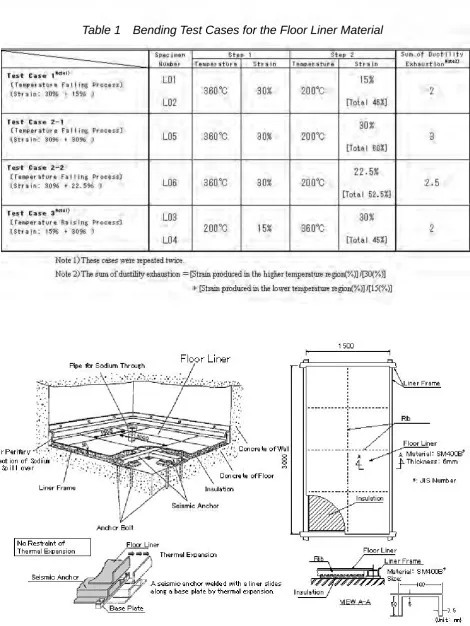
The floor liners of MONJU are made of steel (SM400B: Japanese Industrial Standard No.) in order to prevent structural concrete from contact with spilt sodium in the event of sodium leakage as shown in Figure 1. When sodium spills over the floor liner, the liner is deformed by the thermal expansion, and extremely large strains are locally concentrated at the discontinuity of structure or the thinning parts of corrosion (Figure 2). As for the floor liner, the allowable values of the strain are determined in the lower temperature and in the higher temperature, respectively. The values are 15% for the temperature range of 0°C to 350°C and 30% for the temperature range of 350°C to 1000°C (Figure 3). These values include a design margin which is smaller than the half of critical strain values obtained by a material experiment in each temperature range.
3. THEORY OF DUCTILITY EXHAUSTION
When the structural integrity to the strain is evaluated, it should be better to calculate how much the material has consumed (exhausted) its ductility, instead of a simple comparison of produced strain with a critical value to failure. Namely, the steel structure shall be confirmed whether ductility exhaustion[4] of its material under the actual condition is satisfied with the following expression. The evaluation should be performed by considering material properties. But in a practical design equation, critical values are generally smaller than those of material properties in order to take a design margin.
“[Thermal strain produced in the lower temperature region]/[Critical strain of the lower temperature region]
+[Thermal strain produced in the higher temperature region]/[Critical strain of the higher temperature region]”
≦1
The above expression is Equation 1.
4. APPLICATION OF THE DUCTILITY EXHAUTION METHOD
4.1 Confirmation of the Ductility Exhaustion by Tensile Tests
In order to verify applicability of the ductility exhaustion method, which is based on the above theory, to the floor liner of MONJU, tensile tests were conducted and the sum of ductility exhaustion was examined when the material was broken.
At first tensile tests for the same material as floor liner were conducted in the higher temperature region and in the lower temperature region. Breaking elongation was measured for each specimen. Second, tensile tests under the stepwise change of temperature were conducted. A specimen was initially pre-strained at a prescribed value in the higher temperature region, and then it was loaded in the lower temperature region until it broke. (Similarly, a specimen was pre-strained in the lower temperature region, and it was loaded in the higher temperature region until it broke, too.) Finally, it was examined that the sum of ductility exhaustion was more than 1 by estimating tensile strain produced in two temperature regions.
Figure 5 shows the tensile test results. In this graph the axis of abscissa means a ratio of thermal strain produced in the lower temperature region to breaking elongation of the lower temperature region, and the ordinate thermal strain produced in the higher temperature region to breaking elongation of the higher temperature region. All these plots are located in upper right region of the short dashes line which means the sum of ductility exhaustion of 1. That is:
A + B ≧1
A: Thermal strain produced in the lower temperature region / Breaking elongation of the lower temperature region
B: Thermal strain produced in the higher temperature region / Breaking elongation of the higher temperature region
Therefore, it was verified that the ductility exhaustion evaluation could be applied to the floor liner material.
4.2 How to Apply the Ductility Exhaustion Method to the Design
As shown in the above chapter, it was confirmed that the ductility exhaustion method could be applied to the floor liner material. A proper margin is generally requested for a design criterion compared with the material data. Namely, the sum of ductility exhaustion which is calculated by the thermal strain under the actual condition must be limited much smaller than the breaking elongation or a critical strain at each temperature as a design allowance must be limited much smaller than the breaking elongation value.
This time, the latter concept was adopted as a design criterion to evaluate the floor liner of MONJU. The following values were tentatively adopted as allowable strains based on the ductility exhaustion method: 15% for the temperature range of 0°C to 350°C and 30% for the temperature range of 350°C to 1000°C, which are mentioned in chapter 2. These values are smaller than the half of critical strains to failure, as shown in Figure 3. Therefore, the design criterion based on the method of ductility exhaustion is expressed as follows.
“[Thermal strain produced in the lower temperature region]/[Allowable strain of the lower temperature region]
+[Thermal strain produced in the higher temperature region]/[Allowable strain of the higher temperature region]”
≦1
The above expression is Equation 2.
4.3 Confirmation of Validity by Bending Test
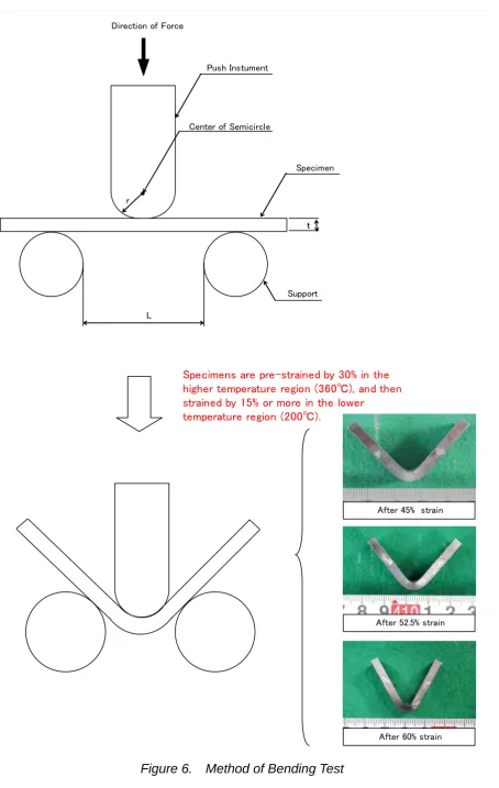
To confirm validity of the above criterion expressed by Equation 2, a bending test was carried out for the liner material of MONJU.
The test was performed in a temperature falling process and specimens were initially strained by 30% in the higher temperature region and then strained by 15% or more until they broke in the lower temperature region. This test means to confirm whether Equation 2 included an enough margin as a design criterion:
On the other hand, the bending test was also conducted in a temperature raising process. Specimens were initially given 15% strain in the lower temperature region and then 30% strain in the higher temperature region, which meant the sum of ductility exhaustion was 2, and they kept their integrity without cracking.
4.3.1 Bending Test Procedure
The bending test was carried out as shown in Figure 6. The pre-strain of a specimen was loaded by regulating the stroke of loading equipment. The relation between the amount of the stroke of the loading equipment and the strain had been obtained at room temperature in advance of the test (see Figure 7).
4.3.2 Bending Test Result
The load-strain curve of the floor liner material was obtained as shown in Figure 8. It was revealed that the liner material could keep its ductility without damage until the final state though the strain of specimens exceeded the allowable value in the lower temperature region as shown in Figure 8. The specimen of the floor liner material after the bending test in a temperature falling process is shown in photo 1. The crack did not occur in cases of the strain of 30% at 360°C and 15-22.5% at 200°C, except for case 2-1: the strain of 30% at 360°C and 30% at 200°C. The crack was not detected in a temperature raising process: the strain of 15% at 200°C and of 30% at 360°C.
4.3.3 Discussion of Validity of a Design Criterion
The bending test results are plotted in Figure 9. This figure shows the relation between the design criterion based on ductility exhaustion method and excessively strained bending specimens. An abscissa means a ratio of a bending strain to the allowable strain in the lower temperature region and an ordinate a ratio of a bending strain to the allowable strain in the higher temperature region. The allowable strains are 15% for the lower temperature region and 30% for the higher temperature region, respectively. Neither a mark of □ nor a mark of ○ in the figure shows a datum of the specimen with cracking. The mark of □ represents 30% strain in the higher temperature region and 15% strain in the lower temperature region, and the mark of ○ 30% strain in the higher temperature region and 22.5% strain in the lower temperature region. Thus, it is assumed that the total sum of ductility exhaustion of failure might be placed between 2.5 and 3. It means that the design criterion, which is shown as the short dashes line in the figure, has approximately 2.5 times larger margin for the break caused by strain.
Therefore, it was verified that the design criterion expressed Equation 2 was conservative to evaluate the structural integrity of the floor liner of MONJU which is locally strained by the thermal deformation.
5. IMPROVEMENT OF DESIGN MARGIN OF THE FLOOR LINER
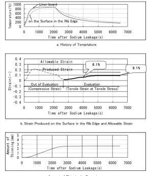
The inelastic analyses for the floor liner of MONJU were performed in a temperature changing process under the most severe condition sodium leakage. As a result, the thermal strain of 6.1% was produced in the higher temperature region at 4008 seconds after the sodium leakage and that of 9.1% in the lower temperature region at 6042 seconds after the sodium leakage at the corrosion thinning part on the surface of the outer rib edge (Figure 2 and Figure 10).
In this case each strain is smaller than the allowable strain. But the strain produced in a temperature falling process has a design margin of 0.61, which means 9.1% of a calculated strain to 15% of an allowable strain.
If the design criterion based on the ductility exhaustion method is applied to the assessment of the structural integrity of the floor liner which is thermally strained by spilt sodium, evaluation of the design margin is as follows.
[Thermal strain produced in the lower temperature]/ [Allowable strain of the lower temperature region] +[Thermal strain produced in the higher temperature]/[Allowable strain of the higher temperature region] = [9.1-6.1(%)]/[15(%)] +[6.1(%)]/[30(%)]
= 0.40
The design margin is improved by approximately 20% compared with a simple strain evaluation. Thus, an application of the ductility exhaustion method to the large strained problems of the steel structures is more practical and helpful than the conventional method, which means a simple comparison of the strain produced in the steel structure with the allowable value of the strain at each temperature.
6. CONCLUSIONS
REFERENCES
[1] E. OKUDA, M. MORISHITA, M. ICHIMIYA, K. TSUKIMORI, M. AKATSU, T. ASAYAMA, F. UENO, T. KOBAYASHI, K. ITO, (2001), Proceedings of 9th International Conference on Nuclear Engineering (ICON 9), No.693
[2] T. ASAYAMA, M. KOI, (2001), Proceedings of 9th International Conference on Nuclear Engineering (ICON 9), No.694
[3] K. TSUKIMORI, T. KATO, I. FURUHASHI, K. IWATA, M. AKATSU, (2001), Proceedings of 9th International Conference on Nuclear Engineering (ICON 9), No.779
[4] P. BOOTH, S.K. BATE, P.J. BUDDEN, (1996), “CREEP-FATIGUE ASSESSMENT OF A THERMINA TEST SPECIMEN USING THE R5 PROCEDURE”, Proceedings of a Technical Committee meeting held in Manchester, United Kingdom, IAEA-TECDOC-933
Table 1 Bending Test Cases for the Floor Liner Material
Figure 4.
Result of Tensile Test
(19.9% at 700°C
→
Until Break at 200°C)
Figure 5. Confirmation of Validity of Ductility Exhaustion
0 0.1 0.2 0.3 0.4 0.5 0.6 0.7 0.8 0.9 1
0 0.1 0.2 0.3 0.4 0.5 0.6 0.7 0.8 0.9 1
Ductility Exhaustion in the Lower Temperature Region (Tensile Strain/Breaking Elongation)
Du cti li ty Ex hau st ion i n t he Hi gh er Te mpe ra tu re Re gio n ( Ten si le St rai n/ Bre ak ing E lon ga tio n )
:Constant Temp. Until Break
:500℃,20%→200℃ Until Break
:500℃,25%→200℃ Until Break
:500℃,30%→200℃ Until Break
:350℃,20%→200℃ Until Break
:350℃,30%→200℃ Until Break
:700℃,20%→200℃ Until Break :200℃,15%→500℃ Until Break
:200℃,12%→500℃ Until Break
:200℃,10%→500℃ Until Break
:200℃,12%→350℃ Until Break
:200℃,10%→350℃ Until Break
:200℃,10%→700℃ Until Break
Specimen Push Instument
r
Center of Semicircle Direction of Force
Support
L
t
Specimens are pre-strained by 30% in the higher temperature region (360℃), and then strained by 15% or more in the lower
temperature region (200℃).
After 45% strain
After 52.5% strain
After 60% strain
Figure 7. Relation between Amount of Stroke and Strain
Figure 8. Load-Strain Curves
20.030.0 40.0 50.0 60.0 70.0 80.0
0 5 10 15 20 25
Amount of Storoke(mm)
Strai
n(
%)
TP1
TP2
TP3
↓ 7 . 6 m m S e t t o 5 2 . 5 + 4 %
S e t t o 3 0 + 4 %
↓ 1 2 . 8 m m
↓ 1 6 . 8 m m S e t t o 6 0 + 4 %
Th is Amou nt is assume d to a Presc ribed Strain 6 0% .
Th is Amou nt is assume d to a Presc ribed Strain 5 2.5 %.
Figure 9. Margin Against Failure in Case of Applying Ductility Exhaustion Evaluation
Figure 10. Thermal Strain Produced in the Floor Liner Under the Actual Condition
(Test Results of Inelastic Analyses)
a. History of Temprtature
b. Strain Produced on the Surface in the Rib Edge and Allowable Strain
c. Amount of Thinning by Corrosion 0 200 400 600 800 1000
0 1000 2000 3000 4000 5000 6000 7000 Time after Sodium Leakage(s)
T
empe
rat
ure(
℃
) Liner board
on the Surface in the Rib Edge
0 1 2 3 4 5
0 1000 2000 3000 4000 5000 6000 7000 Time after Sodium Leakage(s)
Am ou nt o f Th in ni ng (m m ) -0.4 -0.3 -0.2 -0.1 0 0.1 0.2 0.3 0.4
0 1000 2000 3000 4000 5000 6000 7000 Time after Sodium Leakage(s)
St rai n( - ) Allowable Strain
Produced Strain 9 .1 % 6.1 %
Out of Evaluation (Compressive Strain)
Evaluation
(Tensile Strain at Tensile Stress)
c. Amount of Thinning by Corrosion