Available online: https://edupediapublications.org/journals/index.php/IJR/ P a g e | 815
Pick and Place the Object Based On Android Application
P. Malathi & V.V. Ramana Rao
1PG Scholar, Dept of ES, Associate Professor,Dept of ES,
2St. Martin's Engineering College, Dhulapally, QuthbullapurMandal, Secunderabad- 500014.
[email protected], [email protected],
ABSTRACT
Recently, android mobile phone has become very useful for our day to day life. Our daily living style has become smarter due to smart works. Smart works means physically we won’t get much strained instead of us we are making use of robots.Robotic technology is playing a key role in the present technologies and in future we can see a lot of improvements in this technology. There are some works were we can’t handle it physically. Those works like removing bomb, Lifting heavy objects, Picking hot Objects, Carrying objects in dangerous Places, Saving person/things in earthquake. To solve this problem we are implementing a Robot. This robot can pick and place the object in the desired place. Here, we are controlling the robot through voice or by text control. We can use this robot for drawing lines, diagrams, sweeping the floor, used as floor wiper by adopting some changes in the present project.
Key words:ARM7, Wi-Fi, Bluetooth, ARM module
I. INTRODUCTION
Robots are with us for fewer than fifty years however the thought of inanimate creations represents a sincere bid whose success is far older. however real robots failed to acquire existence till Fifties and 60s. With the growing invention of transistors and integrated circuits, industry accessorial brains to the sinew of already
existing machines. In 1959, researchers illustrated the possibility of robotic producing once they unveiled a computer-controlled milling machine. Bluetooth technology was created by medium seller Ericsson in 1994.
Omni-Available online: https://edupediapublications.org/journals/index.php/IJR/ P a g e | 816
directional golem. The golem will move left and right and might be turned on the axis purpose [2]. supported the exposure and a few analysis that are done antecedently, this analysis developed a system to manage golem motion, in accordance with the lean of measuring system device for golem phone. In different words, the smart-phones are used as a distant management for golem movement.
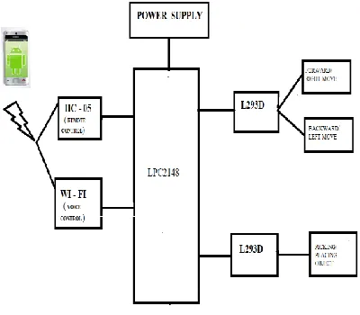
Fig 1: Block Diagram
II. SYSTEM HARDWARE
2.1 LPC2148 Processor:
LPC2148 is a Microcontroller Architecture. The ARM7TDMI-S is a general purpose 32-bit microprocessor, which offers high performance and very low power consumption. The ARM architecture is based on Reduced Instruction Set Computer (RISC) principles, and the instruction set and related decode mechanism are much simpler than those of
micro programmed Complex Instruction Set Computers (CISC). This simplicity results in a high instruction throughput and impressive real-time interrupt response from a small and cost-effective processor core.
Pipeline techniques are employed so that all parts of the processing and memory systems can operate continuously. Typically, while one instruction is being executed, its successor is being decoded, and a third instruction is being fetched from memory. The ARM7TDMI-S processor also employs a unique architectural strategy known as Thumb, which makes it ideally suited to high-volume applications with memory restrictions, or applications where code density is an issue.
The key idea behind Thumb is that of a super-reduced instruction set. Essentially, the ARM7TDMI-S processor has two instruction sets:
• The standard 32-bit ARM set. • A 16-bit Thumb set.
2.2 L293D:
Available online: https://edupediapublications.org/journals/index.php/IJR/ P a g e | 817
by input logic at pins 2 & 7 and 10 & 15. Input logic 00 or 11 will stop the corresponding motor. Logic 01 and 10 will rotate it in clockwise and anticlockwise directions, respectively.
2.3 DC motor:
DC motors are configured in many types and sizes, including brush less, servo, and gear motor types. A motor consists of a rotor and a permanent magnetic field stator. The magnetic field is maintained using
either permanent magnets or
electromagnetic windings..Motors are the devices that provide the actual speed and torque in a drive system. This family includes AC motor types (single and multiphase motors, universal, servo motors, induction, synchronous, and gear motor) and DC motors (brush less, servo motor, and gear motor) as well as linear, stepper and air motors, and motor contactors and
Wireless communication:
2.4 Wi-Fi:
In this project , an Wi-Fi module based on the universal serial interface network standard, built-in TCP / IP protocol stack, enabling the user serial port, Ethernet, wireless network (wifi) interface between the conversions. Through the device, the traditional serial devices do not need to change any configuration; data can be transmitted through the Internet network. The sensor datas will be transmitted to the cloud network through this module.
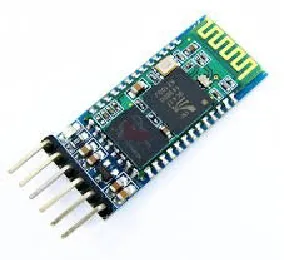
Fig 2: Wi-Fi module
2.5 Bluetooth:
HC‐ 05 module is an easy to use Bluetooth SPP (Serial Port Protocol) module, designed for transparent wireless serial connection setup. Serial port Bluetooth module is fully qualified Bluetooth V2.0+EDR (Enhanced Data Rate) 3Mbps Modulation with complete 2.4GHz radio transceiver and baseband. It uses CSR Blue core 04‐ External single chip Bluetooth system withCMOS technology and with AFH (Adaptive Frequency Hopping Feature). It has the footprint as small as 12.7mmx27mm. Hope it will simplify your overall design/development cycle.
Available online: https://edupediapublications.org/journals/index.php/IJR/ P a g e | 818
Operation:
Slave default Baud rate: 9600, Data bits:8, Stop bit:1,Parity:No parity.
PIO9 and PIO8 can be connected to red and blue led separately. When master and slave are paired, red and blue led blinks 1time/2s in interval, while disconnected only blue led blinks 2times/s.
Auto‐ connect to the last device on power as default.
Permit pairing device to connect as default.
Auto‐ pairing PINCODE:”1234” as default.
Auto‐ reconnect in 30 min when disconnected as a result of beyond the range of connection.
After connect the Bluetooth module, scan for new devices from the PC and you will find the module with the device name “HC‐ 05”, after that, click to connect, if some message appears asking about “Pairing code” just put “1234” as default code.
BLUE LED = ACTIVE (Blinking 500ms period inactive connection, change 1seg with active connection)
Android Mobile phone app:
1) Remote Controller 2) Voice Controller
Android Mobile phone app: - ARM_Voice Controller
Here, we are giving voice instructions to microcontroller via android mobile voice
app. There are few simple steps to follow, voice app to work.
Download and install ARM_Voice app from Google Play Store.
Fig 4: BT Voice Control for Arduino
Turn on your Bluetooth in android mobile then open ARM_Voice app. If not directly open ARM_voice app then it will ask you to allow/turn on Bluetooth after pressing allow button it will open ARM-Voice search till that it won’t open app without Bluetooth on.
In options tab, we have three options connect Robot , Bluetooth Settings, App Info. Select connect Robot to connect with Bluetooth(HC-05) interfaced with microcontroller.
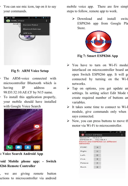
Available online: https://edupediapublications.org/journals/index.php/IJR/ P a g e | 819 You can see mic icon, tap on it to say
your commands.
Fig 5: ARM Voice Setup
The ARM-voice connected with microcontroller Bluetooth which is
having IP address as
98:D3:32:10:AE:CF by N15 name. To install this application properly,
your mobile should have installed with Google Voice Search
Fig 6: Voice Search Android App
Android Mobile phone app: - Switch ESP8266 Remote Controller
Here, we are giving remote button instructions to microcontroller via android
mobile voice app. There are few simple steps to follow, remote app to work.
Download and install switch ESP8266 app from Google Play Store.
Fig 7: Smart ESP8266 App
You have to turn on Wi-Fi module interfaced on microcontroller board and open Switch ESP8266 app. It will get connected by turning on the Wi-Fi networks.
Tap on options, you get update and settings. In setting select Edit Mode to create required number of buttons and variables.
It takes some time to connect to Wi-Fi module, give commands only when it says connected.
Available online: https://edupediapublications.org/journals/index.php/IJR/ P a g e | 820
Fig 8:Switch ESP8266 Buttons
Here, you can edit the button as per your requirements.
By pressing + button, you will create a new button.
By pressing – button, you will edit the current button.
Fig 9:To edit the Switch ESP8266 App Buttons
You can set the variable and label names for buttons
Fig 10: Creating names for new buttons
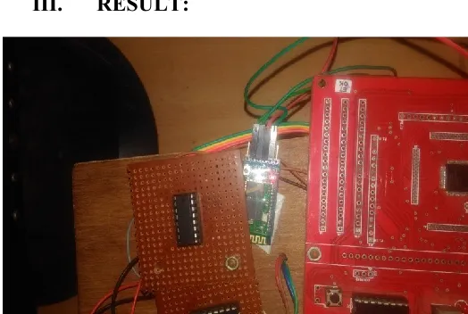
III. RESULT:
Fig 11: Bluetooth Connection
Available online: https://edupediapublications.org/journals/index.php/IJR/ P a g e | 821
Fig 13: Project Kit
IV. CONCLUSION AND FUTURE WORK
Conclusion:
Now a day’s people are giving preference to smart works. In our project we are implemented a robot which decreases man power and increases work efficiency. This robot is used for picking and placing an object in desired place by controlling the robot through remote or by voice. We are giving instructions to robot by remote. Instructions like left/ right/ forward/ backward/ pick/ place which are given to robot by remote/hyper terminal in pc and performs that particular action and picks the object and places the object at the desired location.
Not only with the remote we can move the robot by voice controller. This is an android mobile phone voice controller, which takes input and converts that to text and sends that to processor for processing. This processor activates the appropriate module for processing the output. Here, Robot will pick and places the object at the desired location of the user by voice/remote Controller.
Future Work:
We can move the robot by text also. Robot will move by giving text instructions i.e., possible by image processing. We can interface a camera to check the status of the location also.
REFERENCES
[1]. Song, M., Kim, B., Ryu, Y., Kim, Y., and Kim, S., “Control Robot System Using Android Smartphone”, The 7th International Conference on Ubiquitous Robots and Ambient Intelligence (URAI), Busan-Korea, 2010
[2]. Krofitsch C., Grabler R., “Android-Based LowCost Robot Controller”, Practical Robotics Institute Austria (PRIA)
[3]. Namratha S.N, Anjanaparua, Kumuda. S, Self Balancing Robot Using Android Phone, BMS college of Engineering, IT Department, Bangalore
[4]. Pradeep N., Sharief M., Siddappa M., Building Vision And Voice Based Robots Using Android, 1st Annual International Interdisciplinary Conference, 2013
[5]. M. Klingmann, “Accelerometer-Based Gesture Recognition with the iPhone”, Goldsmiths University, MSc in Cognitive Computing, London,September 2009
[6]. T.A. Baede., Motion Control of an Mobile Robot, National University of
Singapore, Faculty of