Angular Glint Analysis of the 2-D Target above a Rough Surface
Based on Extraction of the Coupling Currents
Qin Xiao1, Si-Yuan He1, *, Yun-Hua Zhang1, Hong-Cheng Yin2, and Guo-Qiang Zhu1
Abstract—In this paper, angular glint characteristics of a two-dimension (2-D) perfect electric conductor (PEC) target above a PEC rough surface are investigated. The induced surface currents on the target and on the rough surface are obtained by employing the method of moments combining UV matrix decomposition technique (MOM-UV). Based on electromagnetic (EM) theory and the phase-front distortion concept of angular glint, the formulae of angular glint for 2-D target are proposed, and angular glint is calculated precisely by using phase gradient method (PGM). The analysis of the result is implemented by means of numerical extraction of the coupling currents and relationship between the phase front and angular glint, thus revealing the effects of the coupling on the angular glint.
1. INTRODUCTION
Angular glint, initially proposed by Howard in 1959, could be explained as the tilt of wave-front normal [1]. As an error, angular glint that leads to the deviation even beyond the radar target extent has become a major factor limiting angular tracking accuracy of tracking radar, especially terminal guidance radar. Therefore, study on the angular glint characteristic of radar targets has great significance for electronic countermeasures (ECM) and electronic counter countermeasures (ECCM), stealth and anti-stealth of target, target recognition and some other areas.
How to calculate angular glint becomes an issue people focused on. Linsday proposed PGM (phase gradient method) using the phase gradient to represent the effect of angular glint [2]. Dunn and Howard proposed PVM (Poynting vector method) when they found that there was a component of the time-averaged Poynting vector orthogonal to the radial direction [3]. Yin and Huang analyzed the unification of PGM and PVM using general formulae [4]. And on this basis polarization was taken into consideration by Kajenski when angular glint was calculated and analyzed [5]. Previous research of angular glint mostly focused on dipoles [2–5] or canonical targets in free space [6]. However, radar targets cannot be divorced from the background such as sea or earth in practice. With the development of electromagnetic scattering modeling technology for targets in a rough surface background [7–12], it becomes an advanced problem with important practical and theoretical significance in radar engineering to study on the angular glint of a target above a rough surface. And it has not been seen in the open literatures or reports so far.
In this paper, the angular glint analysis for a 2-D PEC target above a rough surface is successfully implemented. The method of moments combining UV technique (MOM-UV) [13, 14] is applied to calculate the induced surface currents on the target and the rough surface. Then the angular glint error of composite scattering is calculated by using the phase gradient method (PGM). For the sake of a deeper understanding of angular glint formation process for composite scattering, taking a cylinder target for example, the scattering field phase contributions from different current components are obtained after numerical extraction of the induced surface currents. By these discussions, the effects of the coupling on the angular glint are explored.
Received 29 January 2015, Accepted 16 March 2015, Scheduled 3 April 2015 * Corresponding author: Si-Yuan He ([email protected]).
2. COMPOSITE SCATTERING MODEL AND PHASE GRADIENT METHOD OF ANGULAR GLINT
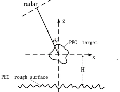
Figure 1 shows the combined model considered in this paper. An infinite long PEC cylinder of arbitrary shape is located above a 2-D PEC random rough surface generated by using Monte-Carlo method in the Pierson-Moskowitz (PM) sea spectrum. Target’s circum radius is R and it centered at a height of H. A truncation of the PM rough surface should ensure that the target is lighted up completely, and the interaction between target and rough surface is sufficient. In this target coordinate system, the distance between radar and reference point satisfies the basic far-field condition. A tapered wave is incident to avoid scattering effects from surface edges, and
Eir= exp
−jkˆi·r 1 +w(r)exp(−tx) (1)
tx=
x+ztanθi g
2
(2)
wr= 2tx−1
(kgcosθi)2 (3)
where g is a parameter to control tapered wave width set as a quarter of the rough surface length in this model to avoid the discontinuity of fringe current,θi the incidence angle, and ˆk= ˆxsinθi−yˆcosθi
the incident wave vector.
Accurate calculation of composite scattering field is a precondition for obtaining angular glint by PGM. Arbitrary electromagnetic wave can be represented as the sum of the TE and TM polarized waves. The scattering of a 2-D target can be separated into these two independent cases, and in this article TM polarization is taken as an example.
TM incident wave perpendicular to thezaxis have only three components: Ei
z,Hxi andHyi, so that
scattering field just have three components: Es
z,Hxs and Hys. The EFIEs is represented as
Esi =jkη
s J
exp
−jk r −r
4π r −r
ds (4)
wherekis the wave number,ηthe intrinsic impedance of free space,rthe distance between the viewpoint and coordinate origin,rthe distance between the source and coordinate origin, andJ is induced current density.
In the MOM-UV method, the boundary of the target and rough surface is separated into segments, and the impulse function is adopted as the basis function and weight function. Then the induced
surface currents are obtained by solving the surface EFIEs. The concrete solving process is provided in appendix. So the far field can be expressed as:
Es(θs, r) =kηF
c
J(x, z) exp (jk(−xsinθs+zcosθs))dl (5)
where
F = √ 1
8πkrexp (−j(kr+ 3π/4)) (6)
and whereθs is the observation angle.
Scattered field can be expressed in the plural form,
Es=kηF[U +jV] (7)
U =
c
J(x, z) cos[ϕ(x, z) +k(−xsinθ
s+zcosθs)]dl (8)
V =
c
J(x, z) sin[ϕ(x, z) +k(−xsinθ
s+zcosθs)]dl (9)
where|J(x, z)|andϕ(x, z) are the amplitude and phase angle of the induced current density. Thus the electric field phase is given by
Φ(r, θs) = argEs=−kr−3π/4 + arctan(V /U) (10)
During the radar antenna angle tracking, the normal of received signal phase front is always regarded as the precise direction of the target. According to PGM, linear glint error is obtained as
e= ∂Φ/∂θs
∂Φ/∂r (11)
where
∂Φ/∂r=−k (12)
∂Φ/∂θs= [arctan(V /U)] = U V
−UV
U2+V2 (13)
U=−
c
J(x, z) sin [ϕ(x, z) +k(−xsinθ
s+zcosθs)]·k(xcosθs+zsinθs)dl (14)
V=−
c
J(x, z) cos [ϕ(x, z) +k(−xsinθ
s+zcosθs)]·k(xcosθs+zsinθs)dl (15)
Echo signal phase-front distortion concepts of angular glint and above derivations of formulae show that target angular glint depends on scattering field phase contributions from induced currents. In order to analyze angular glint characteristic of the target above a rough surface, the angular glint error contributions from different current components are obtained after separating the induced surface currents. The composite scattering is made up of target direct scattering, rough surface scattering, and complicated coupling interaction scattering between the target and rough surface. The total scattered fieldEs can be modeled as a combination of these four scattering components
Es=Es0+Esd+Et0+Etd (16)
where Et0 and Es0 are corresponding to the induced currents on the target in free space Jt0 and the
induced currents on the rough surface in free spaceJs0. Etd andEsd are calculated from the interacting
currentsJtd and Jsd defined by
Jtd=Jt−Jt0, Jsd=Js−Js0 (17)
3. RESULTS AND DISCUSSIONS
Modeling and simulation of the composite scattering system and analysis of angular glint in this paper are implemented for TM polarization. This research method can be a reference for the study about the condition of TE polarization.
In this section, the validation for the numerical method is implemented at first. Then the result of angular glint linear deviation is presented and contrasted with radar cross section (RCS). Furthermore, taking a cylinder above a planar surface as an example, effect on angular glint of induced current components is analyzed by numerical extraction of the coupling currents and calculation of scattering field contributions from them. The simulation result below is acquired in the condition of incident wave frequencyf = 3 GHz and wind speedU = 5 m/s.
3.1. Validation for the Numerical Results
The angular glint liner deviation of a 2-D PEC cylinder with radiusR= 5 m in free space is simulated when angle of incidence θi = 30◦ and compared with the result obtained by analytical solution of cylindrical scattering object. The good agreement of these two curves in Figure 2 verifies the validity of the numerical results.
3.2. Angular Glint Simulation
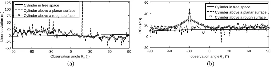
The electromagnetic wave irradiates a 2-D PEC cylinder with radiusR= 5 m and centered at a height ofH = 10 m at angleθi= 30◦. The rough surface length is set at 343.3 m according to [15]. It has been validated that under this setting, the RCS and angular glint are both convergent. The result of a target above a rough surface is given by 500 statistics. Figure 3(a) shows the angular glint linear deviations of cylinder in free space, above a planer surface and above a rough surface while Figure 3(b) shows the RCS of these three scattering systems.
For a 2-D PEC cylinder, the normal of echo wave phase front directs to target center accurately and the angular glint is zero when θs = 30◦ (back scattering) because mirror reflection center is the
-90 -30 30 90 150 210 270
Observation angle θ (°) s analytical solution
MOM-UV method
-12 -8 -4 0 4 8 12
Liner deviation (m)
Figure 2. The validation for the numerical results.
-90 -60 -30 0 30 60 90 observation angle θ s(°)
Cylinder in free space Cylinder above a planar surface Cylinder above a rough surface
-90 -60 -30 0 30 60 90 Observation angle θ s(°)
Cylinder in free space Cylinder above a planar surface Cylinder above a rough surface
-20 0 20 40 60
RCS (dB)
-50 -25 0 25 50 75 100 125
Liner deviation (m)
(a) (b)
point at which wave front touches the cylinder surface. The angular glint increases gradually with the observation angle deviating from 30◦. It can be seen that the angular glint curve slopes gently when the target is in free space while the angular glint of compound target swings violently as a result of influence of the underlying surface. At certain angles, the linear glint error beyond the target size may lead to “blind spots” of radar angle tracking. Comparing the condition of two kinds of underlying surface we can find that the angular glint absolute value of cylinder above a planar surface is larger than that of cylinder above a rough surface (by 500 statistics).
The peak values of angular glint curve always correspond to the valley values of RCS curve. In other words, large angular glint usually appears when the RCS is small. The minimum values of RCS always result from interference, when multiple scattering centers of similar strengths and different phases take effect together. At this moment the scattered field is likely to change dramatically so a great angular glint appears. This negative correlation can be a basis to restrain the angular glint peaks in practical applications.
In Figure 4, the angular glint linear deviations of a square cylinder with side lengths= 7.854 m in free space, above a planer surface and above a rough surface, are shown when the other parameters are the same as mentioned above. The angular glint of square cylinder in free space is zero whenθs=−30◦ while oscillation within target extend appears in the area deviating from this angle. The effect of the underlying surface results in dramatic variations of angular glint curve.
3.3. Analysis of the Phase Front Formation Process for Composite Scattering
The above simulation result indicates that background will give rise to complexity of angular glint which comes from the effect on echo wave phase of induced currents of compound scattering system. Total induced currents of complex target are made up of the rough surface currents (Js) and target currents (Jt). Each part can be decomposed into currents generated from direct motivation by incident wave (Jt0/Js0) and from interaction (Jtd/Jsd).
In this part, echo signal phase and angular glint of each scattering component are calculated by the aid of different current components obtained by the numerical simulation. Then the phase and angular glint contributions from each current component are considered to analyze the rough surface effect on the angular glint. Incident angle is set at 30◦, and θs = 20◦∼40◦ is the range of observation angle. For convenience, phase data are compensated in this paper to gain a smooth curve.
-60 -30 0 30 60 90
Observation angle θ s(°) Square cylinder in free space Square cylinder above a planar surface Square cylinder above a sough surface
-90 -80 -40 0 40 80
Liner deviation (m)
Figure 4. Angular glint of the square cylinder.
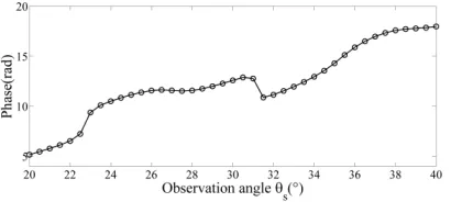
Figure 5 and Figure 6 show the phase and angular glint of the total scattering field. In terms of its physical significance, the phase curve expresses EM wave phase leading or lagging. Whenθs = 20◦∼30◦ andθs= 32◦∼40◦, echo wave phase lags with the increasing of observation angle, while echo wave phase goes ahead when θs = 20◦∼30◦. According to the angular glint concept described quantitatively by echo signal phase-front distortion, angular glint absolute value is large at the angle where the phase changes quickly and small when phase curve is placid.
(a) (b)
Figure 7. Phase contributions from current components. (a) On the cylinder. (b) On the planar surface.
(a) (b)
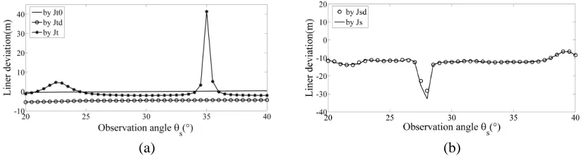
Figure 8. Angular glint contributions from current components. (a) On the cylinder. (b) On the planar surface.
Figure 7 and Figure 8 show the phase and angular glint of different scattering components. The phase of Jt0 is a gentle curve similar to horizontal so the angular glint linear deviation approaches to
zero. That the phase ofJt0 is similar to monotonic means that the phase of this part of echo wave lags
behind with observation angle increasing, so the angular glint linear deviation stays at−5 m. Combined action of these two current components brings about slight fluctuation of the phase curve and makes peak values of the angular glint appears at 22.6◦ and 35◦.
The bistatic scattering of planar surface is very weak at the direction of non-specula reflection. The field phase and angular glint corresponding to Js0 are not given in this paper on account of that the
angular glint calculated by Formulas (9) and (10) can have large error and small contribution to the total result. Moreover, that curves corresponding toJsd andJsare in good agreement also explains that the contributions to angular glint from induce currents on planar surface completely owe to coupled current while effect of planer surface self-scattering can be ignored. When the observation angle is at the direction of specular reflection, or the target is above a rough surface (strong diffuse reflection), the induced currents on the rough surface in free spaceJs0 are equal to the interacting currentsJsd, so they
affect the angular glint of the compound target collectively.
4. CONCLUSION
In this article, the composite scattering field is simulated by an accurate EM model to obtain the angular glint of 2-D target above a randomly rough surface by PGM for the first time. Angular glint of composite scattering has more practical applications than that of target in free space. The study shows that:
1. Rough surface background causes large angular glint even beyond the target extent to appear at some observation angles. That is because composite scattering includes coupling interaction between target and rough surface, so the composite size far exceeds the actual target size.
2. Large angular glint always appears when the RCS is small or changes rapidly. This negative correlation can be a basis to restrain the angular glint peaks in practical applications. 3. By numerical extraction of coupling currents, the angular glint contributions from different current
components can be obtained and corresponded to the formation process of the composite electric field phase, thus revealing the effects of the coupling on the angular glint error.
APPENDIX A. SCATTERING OF 2-D PEC TARGETS BY THE MOMENT METHOD
Arbitrary electromagnetic wave can be represented as the sum of the TE polarized wave and the TM polarized wave. Because parameters of constitutive relation are uniform in one direction, the scattering of a 2-D target can be separated into these two independent cases, and TM polarization is taken as an example.
TM incident wave perpendicular toz axis have only three components: Ezi,Hxi and Hyi, where
Ezir=e−jkˆ·r =e−jk(−xsinθi+ycosθi) (A1)
where θi is the angle between the incident wave and z axis. According to the Maxwell’s equations, scattering field also have only three components: Ezs,Hxs andHys. So the surface induced currents have
only Jz component. Because of the homogeneity of Jz along z,∇ ·J = 0. The EFIEs can be simplified as
Esi =jkη
s Je
−jk r−r
4π r −r
ds (A2)
wherekis the wave number,ηthe intrinsic impedance of free space,rthe distance between the viewpoint and coordinate origin,rthe distance between the source and coordinate origin, andJ is induced current density.
Because of the uniform distribution of Jz along the z axis, a 2-D coordinate (z, t) can be built where z is perpendicular to the metal surface andt is tangent to the metal surface. Then Az can be simplified as
Az =
t Jzdt
+∞
−∞
e−jk
ρ−ρ 2+(z−z)2
4π ρ−ρ 2+ (z−z)2 dz =
t Jz 1
4jH 2 0
k ρ−ρ
dt (A3)
whereH02(k|ρ −ρ|) is the Green Function in a 2-D homogeneous medium space. The boundary of the target and rough surface is separated into N segments ΔCn while the impulse function is adopted as the basis function,
φρ=
1, on ΔCn
0, not on ΔCn (A4)
The impulse function is also adopted as the weight function, and point matching is used to obtain
where
Pmn=kη 4
Cn
H0(2)
k
(x−xm)2+ (y−ym)2
dt (A6)
bm=e−jk(−xmsinθi+ymcosθi) (A7)
Whenm=n,
Pmn≈ kη
4 CnH
(2) 0
k(x−xm)2+ (y−y m)2
(A8)
And when m =n, the Hankel function has singular point. The small argument approximation of the Hankel function
H0(2)(z)≈1−j2 πln
γz 2
(A9)
is used to obtain
Pmn≈ kη
4 Cn
1−j2 πln
γkΔCn
4e
(A10)
where γ = 1.781 is the Euler’s constant and e = 2.718. When using the moment method, internal resonance problem exists in Equation (A6) and can be solved by uniting with MFIEs.
After calculating the equivalent currents, the large argument approximation of the Hankel function
H0(2)(z)≈
2j
πze−jz (A11)
is used to obtain the far field
Es(θs) =kηF
c
Jz(x, z) exp (jk(−xsinθs+zcosθs))dl (A12)
where
F = √ 1
8πkrexp (−j(kr+ 3π/4)) (A13)
ACKNOWLEDGMENT
This work is supported by the National Natural Science Foundation of China under Grant No. 61401515, No. 61301061, No. 61001059.
REFERENCES
1. Howard, D. D., “Radar target glint in tracking and guidance system based on echo signal phase distortion,”Proceedings of the National Electronics Conference, Vol. 15, 840–849, 1959.
2. Lindsay, J. E., “Angular glint and the moving, rotating, complex radar target,” IEEE Trans. on Aerospace and Electronic Systems, Vol. 4, 164–173, 1968.
3. Dunn, J. H. and D. D. Howard, “Radar target amplitude, angle and Doppler scintillation from analysis of the echo signal propagating in space,” IEEE Trans. on Microwave Theory and Techniques, Vol. 16, 715–728, 1968.
4. Yin, H. C. and P. K. Huang, “Unification and comparison between two concepts of radar target angular glint,” IEEE Trans. on Aerospace and Electronic Systems, Vol. 31, 778–783, 1995.
5. Kajenski, P. J., “Comparison of two theories of angle glint: Polarization consideration,” IEEE Trans. on Aerospace and Electronic Systems, Vol. 42, 206–210, 2006.
7. Yelkenci, T., “Imaging of rough surfaces having impedance boundary condition by the use of newton iterative algorithm,” IEEE Geoscience and Remote Sensing Letters, Vol. 7, 190–194, 2010.
8. Guan, B. and J. F. Zhang, “Electromagnetic scattering from objects above a rough surface using the method of moments with half-space green’s function,”IEEE Trans. on Geoscience and Remote Sensing, Vol. 47, 3399–3405, 2009.
9. Liang, D., P. Xu, L. Tsang, Z. Gui, and K.-S. Chen, “Electromagnetic scattering by rough surfaces with large heights and slopes with applications to microwave remote sensing of rough surface over layered media,” Progress In Electromagnetics Research, Vol. 95, 199–218, 2009.
10. Du, Y., J. C. Shi, Z. Y. Li, and J. A. Kong, “Analysing EM scattering from randomly rough surfaces using stochastic second-degree iterative method, sparse matrix algorithm and Chebyshev approximation,” Electronics Letters, Vol. 45, 292–293, 2009.
11. Du, Y. and B. Liu, “A numerical method for electromagnetic scattering from dielectric rough surfaces based on the stochastic second degree method,” Progress In Electromagnetics Research, Vol. 97, 327–342, 2009.
12. Guo, L. X., A. Q. Wang, and J. Ma, “Study on EM scattering from 2-D target above 1-D large scale rough surface with low grazing incidence by parallel MoM based on PC clusters,”Progress In Electromagnetics Research, Vol. 89, 149–166, 2009.
13. He, S. Y. and G. Q. Zhu, “A hybrid MM-PO method combining UV technique for scattering from two-dimensional target above a rough surface,”Microwave and Optical Technology Letters, Vol. 49, 2957–2960, 2007.
14. Deng, F. S., S. Y. He, H. T. Chen, et al., “Numerical simulation of vector wave scattering from the target and rough surface composite model with 3-D multilevel UV method,” IEEE Trans. on Antennas and Propagation, Vol. 58, 1625–1634, 2010.