TECHNICAL BULLETIN
UNIVAC 1107
CENTRAL COMPUTER
CONTENTS
1. UNIVAC 1107 THIN.FILM MEMORY COMPUTER. . . • . • . . . . .. 1-1
General Description. • • • • • • • • • • • • • • • • • • • • • • • • • • • • • • • • • • •• 1-1
Features. • • • • • • • • • • • • • • • • • • • • • • • • • • • • • • • • • • • • • • • • • • •• 1-2 Peripheral Equipment. • • • • • • • • • • • • • • • • • • • • • • • • • • • • • • • • • •• 1-2
2. CENTRAL COMPUTER.. . . • • . . . . • . . . .. . • . . . . .. 2-1 Storage. • • • • • • • • • • • • • • • • • • • • • • • • • • • •• • • • • • • • • • • • • • • •• 2-1 Magnetic Film Memory. • • • • • • • • • • • • • • • • • • • • • • • • • • • • • • • •• 2-1 Core Memory •••••••••••••••••••••••• '. • • • • • • .• • • • • • • •• 2-1 Storage Allocation. • • • • • • • • • • • • • • • • • • • • • • • • • • • • • • • • • •• 2-2 Control. • • • • • • • • • • • • • • • • • • • • • • • • • • • • • • • • • • • • • • • • • • •• 2-4 Indexing Unit. • • • • • • • • • • • • • • • • • • • • • • • • • • • • • • • • • • • • •• . 2-4 Interrupts. • • • • • • • • • • • • • • • • • • • • • • • • • • • • • • • • • • • • • • • •• 2-5 Initial Load Operation (Automatic Bootstrap) ••••••••• • • • • • • • •• 2-5 Arithmetic. • • • • • • • • • • • • • • • • • • • • • • • • • • • • • • • • • • • • • • • • •• 2-5 Adder. • • • • • • • • • • • • • • • • • • • • • • • • • • • • • • • • • • • • • • • • • • •• 2-6 Overflow and Carry Designators. • • • • • • • • • • • • • • • • • • • • • • • • • •• 2-6 Arithmetic Registers. • • • • • • • • • • • • • • • • • • • • • • • • • • • • • • • • •• 2-7 Partial Word Transfers. • • • • • • • • • • • • • • • • • • • • • • • • • • • • • • • •• 2-7 Floating Point Arithmetic ••••••••••••••••••••••••••••••• 2-7 Input-Output. • • • • • • • • • • • • • • • • • • • • • • • • • • • • • • • • • • • • • • • •• 2-7
3. DATA, CONTROL AND INSTRUCTION WORDS . • . • . . . . • • . • . • • . . . • . 3-1 Data Representation •••••••••• •••• • •• • • • • • • • • • • • • • • • • • •• 3-1 Control Words and Control Registers.. • • • • • • • • • • • • • • • • • • • • • •• 3-1 Index Registers... • • • • • • • • • • • • • • • • • • • • • • • • • • • • • •• 3-2 Arithmetic Registers.. • • • • • • • • • • • • • • • • • • • • • • • • • • • • • • • •• 3-2 R-Registers • • • • • • • • • • • • • • • • • • • • • • • • • • • • • • • • • • • • • • •• 3-3 Input-Output Access Control Registers •••••••••••••••••••••• 3-3 Instruction Word. • • • • • • • • • • • • • • . • • • • • • • • • • • • • • • • • • • • • •• 3-4 Two- Address Accessibility. • • • • • • • • • • • • • • • • • • • • • • • • • • • • •• 3-7
5. TRANSFER INSTRUCTIONS.. . . .. .. . . . .. . . . . 5-1 Load. . • . . . . • • • • • • .• . . . . • . . . • . . • . . . • • • • • • . • . • • • • • . • 5-1 Store • . • . • • • • • • • • • • • • • • • • • . • . . • • • • . • • . • . . • • • • . • . . . • 5-5
6. ARITHMETIC INSTRUCTIONS.. . . . 6-1 Addition ...••.•.•••...••••••••••••. ". . •. . ... •. . .• 6-1 Multiplication •••••••.•••••••••••••••••••••...•••... 6-5 Division. . . • . • • • . . • • • • • • • • • • • • • • • • . . . • . . . • . . • . • . . . . • 6-7 Multiple Add and Subtract ....•..•....••..•...•.•• 6-9
7. LOGICAL INSTRUCTIONS. .• . . . • . . . • . • . • • • • . • . . . • . . . • • 7-1
8. SHIFT INSTRUCTIONS. . • . . . .. . . . • .. . . . • . . . . 8-1
9. BRANCHING INSTRUCTIONS - SKIP . • • . . . • . • . . . . • . . . 9-1 Test. • • • . • • • • • • • • • • • • • . . . • . . • . • . • • • . • . . • . • . • • . • • . . . 9-1 Search •••.•.•••••.••••••...•••...•••.••.•.•.••.. 9-5
10. BRANCHING INSTRUCTIONS - JUMP. . . • . . . • . . . • • . . . .. 10-1
11. BLOCK TRANSFER INSTRUCTION. . • • . • • . . . .. 11-1
12. SPE CIAL INSTRUCTIONS. . . • . . . • . . . . .. 12-1
13. FLOATING POINT INSTRUCTIONS .. . . • . . . \ . . . .. 13-1
14. CONTROL CONSOLE. • . . . • . . . .. . . . .. 14-1 Automatic Programming. . . . . . • • • • • . . • • . . . . • • • • • • . .. 14-2
GENERAL DESCRIPTION
The UNIVAC@ 1107 Thin-Film Memory Computer signals the arrival of a third generation of com-puters since it marks the first time thin-film memory is used in a commercially available data-processing system. Thin-film memory - the most significant technological achievement since solid-state circuitry - brings to commercial and scien-tific computer users data control and storage tech-niques never before available.
Designed and developed as a solid-state, general-purpose system, the UNIVAC 1107 Computer util-izes advanced data-processing methods. Its concept of design centralizes the many controls -necessary for high efficiency input and output, concurrent computation, and internal transmission -within the thin-film memory, the "heart" of the system.
As a direct res uIt of its logical design, the UNI-VAC 1107 Computer can reliably and economically process a wide range of applications in either an on-line or an off-line mode. Equally important is the rate of speed at which these applications can be processed: internal speeds of the UNIVAC 1107 System are measured in nanoseconds - billionths of a second. Accordingly, the system is particular-ly well equipped to handle real-time applications.
UNIVAC thin-film, also known as magnetic film, is manufactured by deposition of vaporized magnetic alloys on thin planes of glass under the influence of a strong magnetic field. Because these deposits are made in extremely thin layers, the direction of their magnetic field can be switched in an inter-val of several nanoseconds. This feature allows information to be stored or retrieved at extremely high rates of speed. Immediate benefits include substantial savings in processing time, reduced power requirements, and miniaturized storage units.
Basically, magnetic-film memory consists of an array of minute circular metallic elements, several
1. UNIVAC 1107 THIN-FILM
MEMORY COMPUTER
millionths of an inch thick, deposited on planes (substrates) of glass. Functionally, each metallic deposit (or "dot") can be compared to the ferrite core employed in conventional storage units. Thirty-six "dots" are assigned to each of the 128 words in the thin-film or control memory.
Instead of wires physically threading ferrite cores, the circuitry for magnetic film is printed on MYLAR
*
tape, and then wrapped around glass substrates. Figure 1-1 depicts a glass substrate after deposi-tion of the metallic alloy.Employed primarily in a control capacity, magnetic-film memory provides multiple accumulators, index registers, control-registers, and input-output regis-ters. As a res ult of this arrangement, intricate input-output, arithmetic, and housekeeping oper-ations - which formerly required extensive data manipulation - have now become little more than routine programming functions.
Figure 1-7. Substrate of Magnetic Film.
FEATURES
Among the more prominent features of the UNIVAC 1107 Data-Processing System are:
1-2
• A magnetic-film memory - the most ad-vanced data storage device on the market today.
• A ferrite-core memory for instructions and operands, available in capacities of 16,384 words in one bank or 16,384 words and multiples thereof (up to 65,536 words) in two separately accessed banks.
• Six hundred and sixty-seven nanosecond (0.667 microsecond) cycle time for film memory, complemented by an effective 2-micros econd cycle time for core memory (overlapping of two banks).
• Sixteen bidirectional input-output chan-nels, capable of concurrent input-output transmissions at a maximum rate of 250,000 words (1,500,000 characters) per second.
• Automatic programming, including ALGOL, COBOL, FORTRAN, simulators and assem-blers.
• An executive system for integrating the subroutines required in the processing of multiple programs.
• A highly versatile instruction word that provides for indexing, indirect addressing, automatic incrementation of the modifier, and partial word transmission, as well as specification of both an operand and an arithmetic register.
• A repertoire of instructions that frequently combines two or more data-processing oper-tions in a single command.
PERIPHERAL EQUIPMENT
The input-output section of the UNIVAC 1107 Com-puter System accommodates many different types of peripheral equipment. Some external units, such as magnetic drum and tape units, may be used to provide auxiliary storage. Other devices may serve as input-output equipment; these would include card and tape units, printers, and document-sensing devices. Additional special peripheral equipment can provide information links to other systems.
Standard on-line peripheral equipment for the UNI-VAC 1107 System consists of:
Magnetic Drum Storage Systems (FH880 Drums) Magnetic Tape Units:
UNISERVO IIA Units(Remington Rand UNIVAC format)
UNISERVO IIA Units (IBM format) UNISERVO III Units
Card Readers (80-column or gO-column) Card Punches (80-column or gO-column) High-Speed Printer
Paper Tape Reader Paper Tape Punch
Conventional off-line operations, such as card-to-tape conversions, can be performed on-line with negligible interruption of running programs. In this type of operation, data flows to and from an as-signed memory area. In effect, this memory area serves as a data transfer buffer, functioning in-dependently of the main program.
The Central Computer in the UNIVAC 1107 System consists of four maj or sections: storage, control, arithmetic, and input-output.
STORAGE
Regardless of the selected core memory capacity, each UNIVAC 1107 System is equipped with a separate magnetic-film memory. Consequently, the storage section of the Central Computet encom-passes both a magnetic-film memory and a core memory, along with their respective address, trans-fer, and control circuits.
Magnetic- F ilm Memory
Magnetic film in the UNIVAC 1107 System provides a 128-word control memory. Each word, is capable of storing 36 bits of information. The film array is such that word selection determines which 36 bits are to be accessed. Operating in the parallel mode, read access time for any film-memory address is 167 nanoseconds (0.167 microsecond); complete cycle time is 667 nanoseconds.
The magnetic-film memory is the most frequently used area in the entire UNIVAC 1107 Data-Pro-cessing System. As a general rule, in the time it takes to make a single reference to core memory, film memory will have been referenced threetimes. Carried a step further, approximately 1.5 million references per second can be made to film memory.
*
Core Memory
Core storage in the UNIVAC 1107 System con-sists of small doughnut-shaped magnetized cores of ferrite material. Depending upon its direction of magnetic orientation, each core (similar to the metallic "dot" in film memory) is capable of repre-senting one of two stable states: on or off (lor 0).
The cores themselves are arranged in planes. Wires thread the planes in a pattern similar to that of the vertical and horizontal coordinate lines on a map. The intersection of two wires determines a specific core. Data stored in core memory is ac-cessed via word selection and read in the paralle I mode.
* In this case references to core memory are overlapped to provide an efficient communications rate of 500,000 words per second.
2.
CENTRAL COMPUTER
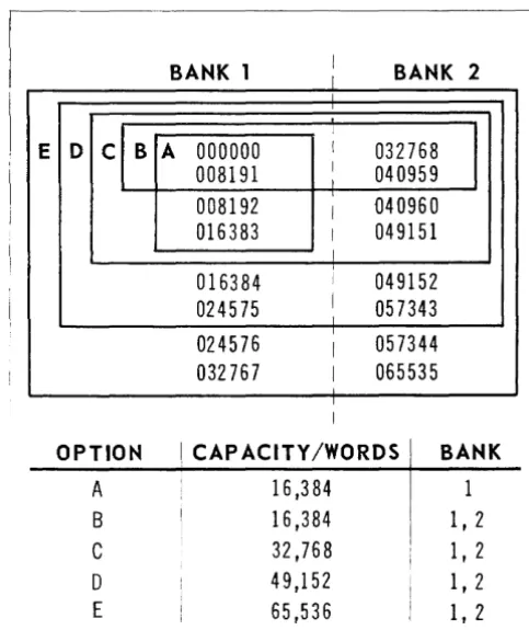
UNIVAC 1107 core memory is available in options of 16,384 words in one bank; or, 16,384,32,768, 49,152, or 65,536 words in two banks. Read access time for any core-memory address is 1.8 micro-seconds; complete cycle time is 4.0 microseconds.
In a two-bank installation, regardless of the selec-ted memory capacity, the full range of lower-order addresses (0 through 32,767) apply to bank one, while the full range of higher-order addresses (32,768 through 65,535) apply to bank two.
To illustrate this principle, assume a two-bank in-stallation has a total storage capacity of 32,768 words. As shown in Figure 2-1 (Option C), the addresses available to the programmer are 0 through 16,383 in bank 1 and 32,768 through 49,151 in bank 2, for a total of 32,768 locations. Note that bank 1 does not end at address 16,383 and bank 2 begin with address 16,384. Instead, each bank has the full complement of addresses. In this manner, the system lends itself to future expansion.
BANK 1
J BANK 2
I
E D C B A
000000
I032768
008191
I I040959
008192
I040960
016383
I049151
I
016384
I049152
024575
I I057343
I
024576
I057344
032767
I065535
I
OPTION I CAPACITY/WORDS BANK
A
16,384
1
B
16,384
1, 2
C
32,768
1,2
D
49,152
1, 2
E
65,536
1, 2
BANK 1 BANK 2
DECIMAL OCTAL BINARY DECIMAL OCTAL BINARY
000000
000000
.
a
000 000 000 000 000
032768
100000
1 000 000 000 000 000
.
008191
017777
a
001 111 111 111 111
040959
117777
1 001 111 111 111 111
008192
020000
a
010 000 000 000 000
040960
120000
1 010 000 000 000 000
1---
---
-...--- --- ---
,I
.
I016383
037777
a all
111 111 111 111
: 049151
137777
1
all
111 111 111 111
~I ACTUAL ADDRESS ACCESSED I
--- --- _ _ _ _ _ _ _ _ _ _ _ _ _ _ _ _ _ _ _ _ _ _ _ _ _ _ _ _ 1
016384
040000
a
100 000 000 000 000
049152
140000
1 100 000 000 000 000
024575
057777
0 101 111 111 111 111
057343
157777
1 101 111 111 111 111
024576
060000
0 011 000 000 000 000
057344
160000
1
all
000 000 000 000
I --- --- --- --- ---- --- ---I
I ,
032767
077777
0 111 111 111 111 111
: 065535
177777
1 111 111 111 111 111
I
-I
I PROGRAM REFERENCED ADDRESS I
_ _ _ _ _ _ _ _ _ _ _ _ _ _ _ _ _ _ - _ _ _ _ _ _ _ _ _ _ _ _ - __ I
Figure 2·2. Decimal, Octal, and Binary Values of Core Storage Addresses
In a system that uses less than maximum storage, an address that exceeds the capacity of a selected bank will automatically reference an address in that same bank with fewer significant bits. For example, if memory capacity is 32,768 words and the programmer inadvertently references address 65,535, the last address for maximum storage, the program will automatically access location 49,151, the highest actual address in bank 2.
The principal advantage of a two-bank installation is that by simply storing data in one bank and in-structions in the other, core-memory references in consecutive instructions can be overlapped. Under this arrangement, the cores that contained the cur-rent instruction's operand can be read, while the cores in the alternate bank, containing the next instruction, are being read. The net result is an effective cycle time of 2.0 microseconds (see Figure 2-3).
Storage Allocation
The addresses of the 128 locations in film memory are identical to those of the first 128 locations in core memory. Distinction between memory units is based on whether the address is specified by the program-address register (P) or a designator in the instruction in the Program Control Register (PCR).
If the address of a location that can be found in both film memory and core memory is contained in P, an instruction word is being accessed. Con-sequently, program control will automatically
refer-2-2
ence the appropriate location in core memory. Con-versely, if the address is specified via the peR,
a data word, a constant, or a control word, is stipulated. In this case, program control auto-matically references film memory.
,
i
Data Instruction
Cycle I
Bank
i Bank
Time !
Microseconds:
1
2
2
iREAD
I
---~--T---
-RESTORE
!'
-2
READ
READ
1 - - - -1 - - - -1
-2
RESTORE RESTORE
t--,
2
READ READL _____
' - - _ _ _ _ _ _ L - _ _ _ _ _ _ }Overlap. Effective Cycle Time
of 2 p.s
Magnetic-F ilm Memory
The 128 locations in magnetic-film memory are reserved for data words, constants and control words. These locations can only be accessed by load, add, mask, and similar instructions; that is, an instruction that designates an internal oper-ation. For example, when a programmer specifies that the contents of location 20 are to be stored in location lIS, the contents of film-memory
loca-tion 20 will be transferred to film-memory location
115.
A particular location in film-memory is accessed via designators in the instruction in the peR. The contents of the specified location are then trans-ferred either to the arithmetic section or to another memory location.
An input-output instruction, that is, one that speci-fies transfers to or from peripheral equipment, will only reference core memory. This means that when-ever the contents of a film-memory location are to serve as output, they must first be transferred to a core-memory address. Similarly, input data that is to be operated on arithmetically must be trans-ferred first to core memory, and then, to film memory.
In this respect, the UNIVAC 1107 incorporates a unique safety feature. In refusing input-output instructions direct access to magnetic-film memory, the system precludes the possibility of a program-mer inadvertently overlaying input data on control-memory data essential to computation.
CONTROL MEMORY (Thin-Film)
As employed in the Central Computer, magnetic film supports a comprehensive data-processing network. For example, many of the system's advanced processing and input-output options re-sult from the 63 magnetic-film locations that pro-vide:
Index registers
Arithmetic registers
Input-output access control registers
Temporary program address register
Real-time clock
Mask register
Repeat count register
The programmer is free to use the remaining loca-tions as auxiliary storage for data and constants.
Core Memory
Just as film memory is reserved for data words and is protected from external operations, the first 128 locations in core memory are reserved for instruction words and are fully protected from all internal write operations. Because of this logical design, these locations are particularly well suited for a bootstrap routine.
Individual instructions or a bootstrap routine may be loaded into the first 128 locations
*
in core memory only by means of input peripheralequip-* The bootstrap routine may utilize up to 224 locations in core memory.
CORE MEMORY
BANK 1 BANK 2
128
8,192,16,384 or 32,768
8,192,16,384 or 32,768
36-bit Words
36-bit Words
36-bit Words
0.667 JLs Cyc Ie Time
2p.s Cycle Time (effective)
2p.s Cycle Time (effective)
Zo I I So Sl :
(Storage Address :
Zl
S2 :
Z2
(I/o
Register) I I (Storage Address Register)I Register) I
(I/O Reg ister) (Storage Address I
Register) I (I/O Register)
mente Once stored, the instructions can be al-tered only by reading new instructions, via peri-pheral equipment, into the same locations. Behind this stipulation lies the general rule that when-ever the designators in an instruction specify an address that may be found in both film memory and core memory, the program will reference film memory.
Instructions stored in the first 128 core-memory locations are accessed via P, the program address register. The contents of the specified location are then transferred to PCR, the program control register, for execution. Note that entry into PCR can only be gained from core memory.
The next 75 core-memory locations (addresses 128 through 202) are reserved for interrupts and the external status word. The remaining locations in core memory (addresses 203 through 65,535 when maximum capacity is used) may be employed as the programmer desires.
CONTROL
The control section of the Central Computer com-prises the program address register, the program control register, the storage class control decod-ing unit and the indexdecod-ing unit. In addition, this section includes the circuits which supply the control signals necessary to synchronize the execution of instructions.
Control Memory (Thin-Film)
The program address register., P, normally con-tains the address of the next instruction, except during a repeated sequence operation when it contains the remaining number of times the in-struction is to be executed. The program control register, PCR, contains the instruction currently being executed. The storage class control decod-ing unit, SCC, decodes the effective operand ad-dress for subsequent referencing to magnetic-film memory or core-memory bank 1 or bank 2.
Indexing Unit
The indexing unit, containing an adder and sens-ing circuits, is shared by both program control and input-output control. Program control uses the indexing unit to: advance the P-register by 1 each time an instruction is executed (provision is thus made for sequential execution of instructions); to count down and control repeated sequences; and to perform address modification, and incrementa-tion.
The indexing unit performs address modification as 18-bit one's complement addition. Because the maximum operand address utilizes 16 bits, two binary O's are placed to the immediate left of the operand address. After modification, the two most significant bits in the effective operand address are dropped and the 16-bit address is transferred to SCC.
CORE MEMORY
1--- - ---
- - I I 128 thirty-six bit words :2p,s Effective Cycle Time
C---
~ ~~_~!~~ _1~= ~
-=
~ ~-j f---~
-=
==
~~~ ~
-=-
-=----=
=-
J
~
8,192,16,384 or 32,768 :I
8,192,16,384 or 32,768!
I 0.667 p,s eye Ie time :I
r--- --- --
--II
Zo
.L
So
I
---~---
----
,....----I
i 1
rl
scc
r
INDEXING
UNIT
2-4
I Thirty-six bit words I I Thirty-six bit words I
t---- - - -
T--- -
---i I- - - -----.,..---1
Sl --L Zl I
I
S2 : l~_ ___ :
---~---
---r---
----
- - _...&... - - - ....P
PROGRAM
CONTROL
Input-output control uses the indexing unit to specify both the number of words to be transferred and the locations to or from which data will move.
rupt is associated with a fixed address which auto-matically provides entry into a subroutine cor-responding to the event or circumstances that caused the interrupt.
Interrupts Initial Load Operation (Automatic Bootstrap)
Interrupts are special control signals which divert the attention of the computer from the main pro-gram to a particular event or set of circumstances. In the UNIVAC 1107 System, provision is made for several classes of interrupts.
There is an external interrupt for each of the 16 input channels. These interrupts enable peripheral equipment to request access to the Computer. There are internal interrupts corresponding to each of the 16 input access-control words, 16 out-put access-control words, and the 16 external function words. An internal interrupt is also pro-vided for the real-time clock.
An initial load op,eration is provided for initial loading of programs and for program restoration. The initial load operation will read a maximum of 224 words from peripheral equipment into the first 224 locations in core memory. Upon termination of the reading, program control is transferred to the program contained within these 224 words. The initial load operation may be initiated manually or by program control.
An additional external interrupt is available for real-time system synchronization. This interrupt is independent of the input-output channels. It accepts signals of any frequency from an external generator which may be a supplementary real-time clock for the Central Computer or the master clock for a multiple-computer installation.
In the UNIVAC 1107 System, interrupts need not be tested to reveal their source. Instead, each
inter-ARITHMETIC
The arithmetic section of the Central Computer in-cludes threshold sensing circuits, counters, arith-metic sequence control circuits, a shift matrix, temporary storage registers, and an adder.
The threshold sensing circuits determine the equality and relative magnitude of the contents of specified registers. The counters are employed during multiply and divide opera~ions. Sequence control circuits govern the execution of add, sub-tract, multiply, divide, shift, and
test-relative-CORE MEMORY
_~~.!!~~!...m~ry i!hi!!:~~l_ 21ls Effective Cycle Time
I
j"'---SANK1---,
1 - - - - -BANK2---'
I 128 thirty-six bit words
1---..,
r - - - ,
I O.667 1ls
cycle time 1 8,192,16,384 or 32,768 I I 8,192,16,384 or 32,768 ,I---r---~
: ___
Th~y-S~~i!..w~rds
___~ ~
___Th~y-S~..':i!...W~~S---l
l--1"~~
__
...J ___~--
- I!....--l!...--.l---r~!.
-
-_II---~---L-T~!.~--~
--J--
j I---l--[-=---=--=-~-~=--=--=--=±-=--=--=-~-L-~--~-=-~===~---;
I1
II I r - - - I I
. I r --I SCC 1 I
I I
L ____
..!
II I I
I_....L__
I !: : INDEXING
L -
L - - - -.. ;---- ... - - - ;1 I UNIT
J- -- ---
- - - 1 P I1 I _ _ _ _ _ ...!---~
,---1
I I
1---,
I
1 - - -1-
---1
PROGRAM II - - _ _ 1 PCR I ' - - - 1 I CONTROL ~---~ 1
I 1 I
• _ _ _ _ _ 1 , _ _ _ _ _ _ _ 1
Figure 2·6. Arithmetic Paths and Units
X·REGISTER
t
ARITHMETIC NETWORK &
magnitude instructions. The shift matrix shifts data from 0 through 36-bit positions in a shift oper-ation.
During the actual execution of an arithmetic in-struction, temporary storage registers within the arithmetic section itself are employed. The Central Computer first determines that the arithmetic sec-tion will be utilized in a given operasec-tion. Data is then transferred automatically, via the X-register*, to a temporary storage register of the arithmetic section. The X-register and the temporary storage registers cannot be addressed by the programmer.
Adder
The adder in the UNIVAC 1107 System is a 36-bit one's complement subtractive adder (mod 236 - 1). Additions are performed in the following manner:
Assume the value 2 is to be added to the value 6. In core storage, the binary equivalents of these values are:
000000000000000000000000000000000110
=6
000000000000000000000000000000000010
=2
In executing the instruction, the adder first complements the value 2:
111111111111111111111111111111111101
=one's complement of 2
Next, the adder subtracts the one's complement of 2 from the value 6. The subtraction itself in-volves an "end-around borrow," whereby the process of borrowing from the digit to the left may carry from the leftmost digit in the minuend (value 6) to the rightmost digit in the remainder. It will continue moving to the left in the remain-der until the borrow is satisfied:
''a\\'a\\\'a\\\\\\\\'a\\\\\\\\\\'a\\\o
1\0
=6
111111111111111111111111111111111101
= one's complement of 2o
00000000000000000000000000000000100\
=8
end-around b o r r o w - - - -...
+
In the example, the binary 1 in digit position 3* in the subtrahend cannot be subtracted from the binary 0 in the corresponding minuend posi-tion. If the subtraction is to continue, a binary 1 must be borrowed from a digit to the left in the minuend. However, digit positions 4 through 35 all contain binary O's. At this point an end-around borrow occurs; that is, the needed binary digit is taken from the remainder. As it happens, the first bit position in the remainder contains the binary 1 needed to satisfy the borrow.
After the end-around borrow, computation ad-heres to the rules of .binary subtraction. The remainder is the sum of the values 6 and 2.
Overflow and Carry Designators
Associated with the adder are two special tors: the overflow designator and the carry designa-tor. Eight instructions affect the two designators: the four basic add instructions and the four basic subtract instructions - operation codes (in octal notation) 14 through 21, 24 and 25.
Upon execution of one of the eight instructions, both designators are cleared. After addition has been performed, the designators remain in their respective states (set or clear) until another one of the eight instructions is given. Both designators are set in time to be tested immediately after the affecting instruction.
The overflow designator is set upon generation of a significant bit in the sign position. This condi-tion can only arise when the values that are added have like signs. Specifically, a positive result of two negative quantities will set the overflow designator, as will a negative res ult of two posi-tive values.
The carry designator is set whenever an end-around carry (no borrow) is generated. The condition of the carry designator is determined by the following rules:
POSITIVE NEGATIVE
VALUES RESUL T RESULT
A positive and U negative Set Clear A negative and U positive Set C lea r A negative and U negative Set Set A pos itive and U positive Clear Clear
* X is the 36-bit exchan~e re~ister providin~ entrance and exit * Readin~ from ri~ht to left the bit positions are numbered to the arithmetic section. 0 throu~h 35.
The following additions will always set the carry designator:
1. Any number added to its complement
2. All O's added to all l's.
3. Any number added to a1I1's.
4. AlII's added to alII's.
Arithmetic Reg i sters
Sixteen arithmetic or A-registers, directly address-able by the programmer, are availaddress-able for storing operands and results of arithmetic operations. These 16 registers are not to be confused with the non-addressable temporary storage registers within the arithmetic section itself.
As previously pointed out, during actual computa-tion temporary storage registers in the arithmetic unit are utilized. However, these registers are not capable of retaining initial data or final results from one instruction to another. Consequently, all such information is transferred automatically to the A-registers specified in the instructions. The 16 A-registers, then, function as accumulators.
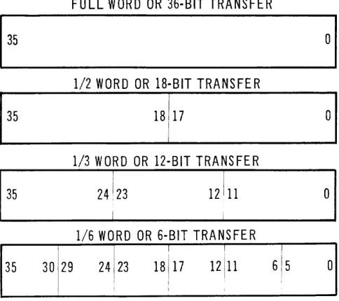
Partial Word Transfers
Word transmissions between the arithmetic section and core memory can be directly segmented into halves, thirds, or sixths. This flexibility allows the Central Computer to operate upon one of eleven poss ible portions of a word or the entire 36-bit word itself, as shown in Figure 2-7. The selected data in a partial word transfer from memory is shifted automatically to lower-order positions in the arithmetic section. By means of this feature, computation can be performed immediately after the partial words have been transferred, without first calling for such housekeeping instructions as shiftso
Along with partial word transfers, special add and subtract instructions are available to the program-mer. Upon execution of one of these instructions, parallel addition or subtraction of two or three fields within a single data word is performed.
Floating. P oi nt Arithmetic
In the UNIVAC 1107 System, floating-point arith-metic has been made a hardware, rather than a software or programming, function. Seven
instruc-tions are devoted exclusively to floating-point arithmetic. Addition, subtraction, and multiplica-tion always store a 2-word result. Both results contain their appropriate characteristics. Division produces a quotient and a remainder, both of which are in the floating-point format. The 2-word res ults of these floating-point instructions lend them-selves to programmed double-precision arithmetic.
INPUT -OUTPUT
The input-output section of the Central Computer provides the data paths and control circuits neces-sary for direct communication between core memory and peripheral equipment. Data transfers may be scheduled over a maximum of 16 bidirectional in-put-output channels. When 16 channels are oper-ating concurrently, word transfers can be multi-plexed to provide a maximum communication rate of 250,000 words (1,500,000 characters) per second. Of course, such high-speed input-output data trans-fer rates are rarely maintained for more than brief periods.
The main computer program establishes the initial communications path between core memory and the peripheral equipment. From this point on, indi vidual word transfers are governed by input-output access-control circuits. These circuits monitor the num-ber of words to be transferred and specify the core-memory addresses to and from which data are transmitted. In this way, the access-control cir-cuits allow the Central Computer to res ume execu-tion of the main program.
FULL WORD OR 36-BIT TRANSFER
1
35
01
1/2 WORD OR 18-BIT TRANSFER
1
35
18) 1701
I
1/3 WaR DaR 12 -BIT T RAN S FER
1
35
24!23
1211101
1/6 WORD OR 6-BIT TRANSFER
! ! I I i
35
30
1
29 24
1
23 18
1
17 12 11 615 0
3.
DATA REPRESENTATION
Internal operations in the UNIVAC 1107 System are performed in the parallel binary mode. Since the machine language is binary, data, control, and instruction words must be expressed in pure binary form. However, for convenience in programming, as well as in monitoring internal operations, octal notation can be used.
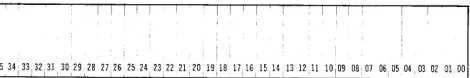
The basic data word in the UNIVAC 1107 System, as shown in Figure 3-1, utilizes 36 binary digit positions. Position 35 contains the sign bit, bit position 34 is the most significant, and bit posi-tion 0 is the least significant.
I ! I ! i I ;
3534,33,3231,30,29,28272625242322 21,2019,1817,16,151413121110,09080706,0504,03020100
Figure 3-7. Bas ic Internal Data Word.
With one position reserved for the sign, a total of 35 binary digit positions may be used to represent a given quantity. The largest number that can be accommodated in the UNIVAC 1107 Sys tern (ex-clusive of floating-point and double-precision arithmetic) is 235 - 1 or 34,359,738,367.
Positive binary numbers are obtained in the follow-ing manner. The absolute value of the desired number is placed in the low-order positions of a
DATA, CONTROL,
AND INSTRUCTION WORDS
given register. A 0 is placed in bit position 35 and extended right until a binary 1 is reached.
Example
+
9
=000 000 000 000 000 000 000 000 000 000 001 001
Negative binary numbers, on the other hand, are arrived at by complementing (substituting a binary ! 1 for each binary 0 and a binary 0 for each binary 1) the positive binary configuration of the desired negative value. Applying this rule, a negative 9 is obtained by complementing the binary representa-tion of a positive 9.
Example
- 9
=111111111 111111 111111111111111 110 110
NOTE: Positive numbers are characterized by a 0 in bit position 35 and negative numbers by a 1 in bit position 35. Also, in tive numbers the first significant bit posi-tion contains a 1 and in negative numbers it contains a O.
CONTROL WORDS AND CONTROL REGISTERS
Special 36-bit control words are associated with several types of film-memory registers. Data trans-ferred to these registers should adhere to the for-mat of the corresponding control word. Data that is to enter a register which is not associated with a special control word is transferred in the format of the basic data word.
3-2
Index Registers
Fifteen 36-bit registers are available in thin-film memory for index register modification and index counts. Index register word format is as follows: The right half (Q-portion) of the index register word stores the modifier which may be up to 18-bits (including sign) in length; the left half (the 11 portion) of the word stores an increment which can be up to 18-bits (including sign) in size. The index register word format is shown in Figure 3-2.
Q
*
Sign Pos itionsFigure 3.2. Index Register Word.
When an indexing operation is indicated, the ap-propriate modifier is applied to the current in-struction's base execution address. The result is the effective operand address (before indirect ad ..
DECIMAL ADDR ESS OCT AL ADDR ESS
00000 000000
00001-00015 000001-000017
>- 00012-00027 000014-000033
0::
00028-00031 000034-000037
0
~ 00032-00047 000040-000057
w
~ 00048-00063 000060-000077
..J 00064 000100
0
0:: 00065 000101
t-z
00066 0001020
u 00067 000103
00068-00079 000104-000117 00080-00127 000120-000177
00000-00127 000000-000177 00128-00143 000200-000217
>- 00144-00159 000220-000237
0::
0 00160-00175 000240-000257
~
w 00176-00191 000260-000277
~
w 00192-00199 000300-000307
0:: 00200 000310
0
u 00201 000311
00202 000312
00203-65535 000313-177777
dressing, if specified). Then, depending upon the value of a special designator in each instruction, the increment is applied to the modifier. In this way, provision is made for varying the extent of address modification in subsequent indexing oper-ations.
The leftmost bit in both the modifier and the in-crement (or dein-crement) portions of the index regis-ter word specifies these quantities as positive or negative.
Arithmetic Registers
Sixteen magnetic-film locations provide interim storage for arithmetic operands and results. Be-cause four of these locations overlap addresses assigned to index registers (Table 1), the Central Computer in the UNIVAC 1107 System is capable of performing highly sophisticated address modi-fication. For example, in a table look-up applica-tion, the res uIts of a given calculation can im-mediately be applied, as a modifier, to a base address.
FUNCTION
Unassigned (depends on operation) Index Registers (15)
Arithmetic Registers (16)* Unassigned
Input Access-Control Words (16) Output Access-Control Words (16) Rea 1-Time Clock
Repeat Counter
M Register R Registers
T-Register (temporary storage for P) Additional Special Registers Unassigned
Unassigned **
External Request Interrupts (16) Input Data Termination Interrupts (16) Output Data Termination Interrupts (16) Function Termination Interrupts (16) Error Interrupts (8)
Real-Time Clock Interrupt Externa I Status Word
External Synchronization Interrupt U nass igned Core-Memory Addresses
* Me mory addresses 000014-000017 are a Is 0 addressa b Ie as index reg isters ** Normally reserved for Bootstrap Routine.
The format of data that is to be loaded into an arithmetic or A-register is contingent upon the type of arithmetic operation to be performed. In the case of fixed-point arithmetic, operands need only conform with the format of the basic data word. Floating-point arithmetic, however, requires a word format of its own. The floating-point w'ord, depicted in Figure 3-3, contains a 27-bit mantissa, an 8-bit characteristic, and a sign bit.
t::
*
Mantissa .~ Character ist ic
en
35 34 27 26 00
*
Biased by 128 (200 octal)Figure 3-3. Floating Point Word
As previously mentioned, the A-registers function as 16 accumulators; that is, they retain the results of computation from one instruction to another.
R- Registers
Sixteen film-memory locations are designated as "R-registers." Twelve of these registers may be used in any way the programmer desires except, that they, as well as all other film-memory loca-tions, cannot be employed for storing instructions. As shown in Table 1, the remaining four R-regis-ters are assigned the following specific functions:
Real-Time Clock
One of the four assigned R-registers serves as the real-time clock. Every millisecond (the exact tim-ing is 2-10 seconds), the 36-bit number contained
in th Figure 3-5. T-Register Word. by 1. When the count reaches 0, an internal interrupt occurs which causes the main program to jump to address 200 (octal 310). Therefore, the programmer must either load the real-time clock register or provide for recovery from the automatic interrupts generated by the clock every 2-10 seconds.
The real-time clock, along with the other R-ters, the index regisR-ters, and. the arithmetic regis-ters, may be referenced directly either in the oper-and portion of an instruction (u address) or in the arithmetic register designator (a address). (This is known as 2-addres s accessibility, and it is ex-plained further on page .) In respect to the real-time clock, two-address accessibility simplifies the setting and subsequent reading of the count. The real-time clock is not associated with a spe-cial control word.
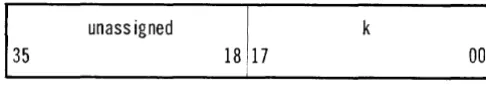
Repeat Count
The second of the four assigned R-registers (refer-red to as the "K-register") provides the repeat count during the execution of an instruction in the repeat sequence mode. Data that is to enter this register should be in the format of the repeat count word, as shown in Figure 3-4.
135
un ass igned
18 [17
k
Figure 3-4. Repeat Count Word.
Initially, the k portion of this control word con-tains the total number of times a particular instruc-tion is to be executed. Then, during the repeat operation itself, k is reduced by 1 each time the instruction is executed. Provision is thus made for a "running" count of the number of execution times remaining in sequence. When k reaches 0, the re-peat operation is terminated.
In certain applications it may be necessary to re-tain the initial repeat count. To meet this pro-gram requirement, load the repeat count (the total number of times an instruction is to be executed) into the unassigned left half of the repeat count word as well as into the k portion.
Mask Reg i ster
The third assigned R-register contains the mask (bit pattern) used in certain logical and test in-structions.· Data that is to enter the mask or
M-register, is in the format of the basic data word.
Temporary Program A ddres s Reg ister
The fourth R-register assigned a specific function is employed as a temporary storage register
(T-register) for the address of the next instruction. Utilized only during a repeat operation, the pro-gram address is stored in the next instruction portion of the T-register word. The format of this particular control word is presented in Figure 3-5.
unass igned Next Instruction
35 00
Figure 3-5. T -Register Word
Input-Output Acces s Control Regi sters
Thirty-two locations in film memory are used to maintain control over data transfers between the
Central Computer and peripheral equipment. Input-output access control wO'{ds are associated with this group of registers. These words, along with the function words necessary to initiate input-output data transfers, are discussed in the UNIVAC 1107 Input-Output Manual. At this point, it is sufficient to note that thirty-two film-memory loca-tions (addresses 32 - 63, Table 1), are reserved for this purpose.
INSTRUCTION WORD
The UNIVAC 1107 Thin-Film Memory Computer is controlled by a program of instructions stored in memory. Each instruction consists of various parts called designators. These designators are identi-fied by letters, as shown in Figure 3-6.
f j
a
b h iu
35 30 29 26 25 22 21 18 17 16 15 0
(6 bits) - Operat i on Code
(4 bits) Operand Instruction or Minor Operation Code* a (4 bits) - A, B, or R-register,or Input-Output Channel
Des ignator* b (4 bits) - B-Reg ister Des ignator h (1 bit) - Incrementation Designator i (1 bit) Ind irect Address ing Des ignator u (l6bits) - Base Operand Address * Instruction determines usage.
Figure 3-6. Basic Instruction Word.
Operation Code, f (6-Bits)
The operation code or f designator, composed of the leftmost six bit positions in the instruction word, stipulates the particular operation that is to be performed. (In certain instructions, when the normal meaning of the j designator is not ap-plicable, the operation code may be expanded to include the ten leftmost bits in the instruction word.)Invalid f (or f and j) values are fault condi-tions which cause an error interrupt to occur. In this event, the main program jumps to a fixed memory address containing the entrance to an ap-propriate error subroutine.
3-4
Operand Interpretation, j (4. Bits)
Normally, the j designator determines whether an entire data word or only a part of it is to be trans-ferred to or from the arithmetic section. As pre-viously mentioned, in certain instructions j serve§> as a minor operation code rather than as a partial word determinant.
In the case of partial transfers, j stipulates which portion of a word (half, third or sixth) is to be trans-ferred. Figure 3-7 shows the j values and corre-sponding word portion transfers to the X-register.
When j equals 16 or 17 (octal), the effective oper-and is taken directly from the instruction word, itself, instead of calling for an operand from mem-ory.
In data transfers to the arithmetic section, when j equals 3 through 7 or 17, the sign of the operand, which is the MSB of the partial word, is extended to the high-order positions in the arithmetic sec-tion. Figure 3-7 shows that thirds are always ex-tended, sixths are never exex-tended, and extension is optional with half words. Figure 3-8 snows the j values and word portion transfers from the X-register to the core memory input-output X-registers Z 1 and Z 2' A j of 16 or 17 (octal) inhibits the data transfer.
A.Register Designator, a (4·Bits)
The type of instruction that is to be executed de-termines the specific usage of the 4-bit a designa-tor.
In arithmetic instructions, a specifies one of six-teen arithmetic registers. In a few instructions, such as Block Transfer; Load Ba Modifier Only;
and Test Modifier, the a designator specifies one
of sixteen index registers. Input-output instruc-tions, on the other hand, use a to stipulate which communications channel and access control word is to be used. In some instructions, the a designa-tor specifies an R-register, using the notation Ra • In the Index Jump instruction, a and j combine to specify any desired control-memory location.
B· Regi ster Designator, b (4· Bits)
The 4-bit b designator determines which of the fifteen index registers, if any, is to modify the instruction's operand address. When b equals 0, address modification is inhibited. (Index register
35 00 Z
j = 0 10
35 00 X
2 12
z
3 13
35 SIGN EXT.
Z Z
4 14
35 SIGN EXT.
Z
5
35 SIGN EXT.
Z
6
16
35 SIGN EXT.
Z
7 17
35 SIGN EXT. 35 SIGN EXT.
35 00 Z Z
j = 0 11
35 00 X
z
1 or 3 12
35 35
z
z
2 or 4 13
35
z
5
35
Z
z
6
35
Z
Iz
7 16 or 17 NO TRANSFER
Ix
z
10
35
Incrementation Designator, h (1- Bit)
The h designator specifies incrementation of the modifier stipulated in the b portion of the instruc-tion word. When h equals 0, the modifier remains unchanged. When h equals 1, the increment portion of the index register word (Figure 3-2) is applied to the modifier portion, thereby altering the sub-sequent address modification.
Ind irect Addressing Des ignator, i (1- Bit)
The i designator specifies either direct or indirect addressing of the operand. Indirect addressing means that the address of the operand rather than the operand itself is contained in the location specified by the u designator. Thus, u contains the address of an address instead of the address of an operand.
When i equals 0, direct addressing applies; when i equals 1, indirect addressing applies. In the latter case, the rightmost 22-bits contained in the loca-tion specified by the u designator replace the right-most 22-bits in the current instruction. Because the b, h, i, and u designators are involved in this substitution, all indexing, incrementing, and in-direct addressing operations can be cascaded.
Base Operand Address, u (16-Bits)
The u designator specifies the base operand ad-dress, that is one of the storage locations in memory. The base operand address u becomes U
(the effective operand address) after specified indexing or indirect addressing operations have been performed.
Most instructions reference an operand in memory, except when j equals 16 or 17 (octal). In this case, the actual operand itself is taken directly from the u portion of the instruction.
The u designator can also be used to provide the shift count or to specify core-memory sections in-volved in a memory lockout.
TWO-ADDRESS ACCESSIBILITY
The index, A, and R-registers can be accessed in one of two ways. First, the film-memory address associated with anyone of these registers can be accessed in the same way any film-memory ad-dress is referenced; that is, by specifying the address in an instruction's u designator. Second,
A, B, and R-registers can be accessed via the a
designator. In this case, the type of instruction to be executed determines which of the three groups of registers is' pertinent to the operation. The value of the a designator specifies a particular register within a group.
Anyone of 16 arithmetic registers or 16 R-regis-ters may be referenced by placing the appropriate value, ranging between 0 and 15, in the a designa-tor. In respect to specially assigned R-registers, the a val ues are as follow s:
VALUE REFERENCE
o
real-time clock1 repeat count register
2 M-register
3 T-register
Sixteen index registers may be accessed via the a
designator. Here again, the a values range between
o
and 15. However, the index register accessed via an a value of 0 c.annot be referenced by the b designator. Accordingly, index register 0 is em-ployed only in certain instructions; for example,B 10 c k Transfer; Load Ba Modifier Only; and Test Modifier. As previously stated, a u
designa-tor containing a value of 0 will inhibit address modification.
Solid-state circuitry within the Central Computer provides the data paths for all internal transfers. The specific circuits over which data moves depend prima rily upon the interpretation of the various designators within the instruction word. (The role of skip and jump instructions in determining data paths is discussed in Chapters 9 and 10.)
EXECUTION CYCLE
To illustrate the functions of the various instruc-tion word designators, assume an arithmetic in-struction, stored at the address contained in P, is to be executed. Assume further that instructions are stored in one bank and data in the other; the j
designator value is not equal to 16 or 17; and the
b designator is not equal to O. Once the arithmetic instruction has been read into peR, the following events take place:
1. The I, j, and a designators are interpreted and the appropriate circuitry is alerted.
2. The lower half of the instruction (h, j, and u designators) is transferred from peR to the indexing unit.
3. The b designator is tested to determine which index register, if any, is to participate in ad-dress modification.
4. If modification is stipulated (the contents of b are unequal to 0), the lower-half of the con-tents of the specified index register is trans-ferred to the adder in the indexing unit.
5. The contents of the u designator, with two O's placed to the immediate left, are transferred to the adder where modification takes place as 18-bit one's complement addition.
4. INTERNAL DATA PATHS
6. Concurrently, the results ofthe previous instruc-tion involved in arithmetic operainstruc-tions are transferred from a temporary storage register within the arithmetic section to the A-register specified in that same instruction.
7. After modification (step 5), the tw-o leftmost bits are ,dropped and the address is transferred from the adder to
see
where it is decoded for subsequent referencing to memory.8. When modification is specified, the h designa-tor in the current instruction is tested to deter-mine whether the index register modifier (Q) is to be incremented (or decremented) by (L\). If h equals 1, the increment is applied to the modifier.
9. After incrementation, the new modifier is sent into the lower half of the index register speci-fied by the b designator. The increment portion remains unchanged.
10. The operand address is transferred from
see
(step 7) to the appropriate storage address register (SO, Sl, or S2).11. The entire 36-bit contents of the location speci-fied in the storage address register are trans-ferred into the appropriate memory unit's Z-register.
12. The i designator is tested to determine whether direct or indirect addressing is stipulated.
14. The actual data transfer, in accordance with the j designator interpreted in step 1, is made from memory (ZO, Zl, or Z2) to the arithmetic
section.*
17. The circuitry alerted by the f designator in step 1 performs the desired operation.
18. The next instruction, referenced in ste p 15, is sent to peR.
15. The program address register, P, is increment-ed by 1 to provide for the sequential execution of instructions.
19. An input-output transmission may be performed while the specified arithmetic operation (step 17) is being completed.
16. The next instruction, stored at the address now
contained in P, is referenced in memory. For most instructions, the preceding steps require 4.0 microseconds. Execution time is extended by 4.0 microseconds when the operand reference is made to the same bank as the instruction reference.
• The J desi~nator is ineffective when the operand is read from film memory (ZO). For certain instructions, 18 bits are transferred to or from a u address specifyin~ film memory. However, the transfer is made as specified by the h designa-tor rather than the j.
The block diagram in Figure 4-1 depicts the prin-cipal paths over which data moves during the exe-cution cycle.
4-2
i~~r;':':':"~;~~·:~,~·~·~~~~~:~;>~··:~:~:§:;ili'::::;:;:;';';'::::;';';';:;::'~:·:·~·~·;.:;
...
:'.~.;.=~.~...
:~.4iliili.:~.:.~.:.::';';';';';;';': .•..••... ···:·Iil!i
~ I_Control~emory (Thin-FiI~1
1 - - - -
2JL~fec~e
Cy<:.!=.Tim~
_ _ _ _ _ _I~~~
.. . . . BANK 1 I I BANK
2
Ii:::t'
128 thirtY-sIx blt~ords Ir---J 1 - - - ,
l~~~~:~
I
0.667 s cycle time I I 8,192.,16,~84 ?r 32,768
I I
8,192.,16,~84 ?r 32,768
,I:l:lll~
I
JL I I Thirty-sIx bit words' L
Thirty-sIx bit words JIll;~~~~ --Zo--T--So-~
"--Zl---'---S-l--' I
-Z2--'-$2--1
~~~~ff~~T~~~~=tt'==1
J ;
rl
see
I
r
I
~
,
I
d
I ,~ IN~EXING
' P ' X·REGISTER ,UNIT A R I T H
~
E TICt
1
I,---r--~~P-R-O-G-R-A-M~
' - - - + f
J
P CRIt---___
-+-_-IARITHMETIC NETWORK &
I
I
MAIN CONTROL
CONTROL
ACCESS CONTROL CIRCUITS
IBR OBR
INPUT-OUTPUT
l l t ·
SYNC. 1---~
SYNC. 16 .. ..1lll
:::~
*
r
, PERIPHERAL PERIPHERAL PERIPHERAL
I
~ll~
EQUIPMENT EQUIPMENT --- EQUIPMENT -[~~~~
& CONTROL & CONTROLIm~
1l11::~;:::::;:::::::;:;;;:::;:;:::::;:;::::::::=;::::::::=;::mm:;:;~:;::::w:::,:::::::::::::::;:;::::::::;::::,:;;<:::::::::::;:;mm;::::::::m.:::~:;wm:;:~;:;~;:;~;:,~:::wJ~il
j DESIGNATOR UNEQUAL TO 16 OR 17
When the current instruction's j designator is neither 16 nor 17 (octal), one of eleven possible portions of a word or the entire word may serve as the operand. The j designator becomes effective when the operand is being transferred between core memory (Zl or Z2) and the arithmetic section.
Consequently, with respect to the j designator, a data transfer to or from film memory (ZO) will always involve a complete 36-bit word. Figure 4-2 shows the data paths utilized when the j designa-tor is neither 16 nor 17.
CORE MEMORY
BANK 1 or BANK 2
-- --- -- -r--
----I
Z I I
I I
partial word selection as specified by j
des ignator
L-X-REGISTER
S
ARITHMETIC SECTION
Figure 4-2. Data Paths for j Unequal to 76 or 77
j DESIGNATOR EQUAL TO 16 OR 17
The j designator may also stipulate that the oper-and is to be transferred from the instruction word itself. This operation is specified by a-j value of 16 or 17 (octal). Then, depending upon the con-tents of the b designator, either 16 or 18 bits will be transferred from low-order positions in the cur-rent instruction to the arithmetic section.*
When j is 16 and b is not 0 (that is, index register modification is specified), the 16-bit contents of the current instruction's u designator serve as the operand. In the indexing unit, two binary O's are placed to the immediate left of the 16 bits taken from the instruction. After the specified modifica-tion has been performed as 18-bit one's complement addition, the i8-bit operand is transferred to the lower half of the X-register for subsequent trans-mission to the arithmetic section. The upper half of this register is cleared to O's.
When j is equal to 16 and b is equal to 0 (modifica-tion is inhibited), an 18-bit operand will be trans-ferred from the instruction word to the arithmetic section. The 18 bits are taken from the current instruction's h, i, and u designators. Once again, the upper half of the X-register is cleared to O's.
A j value of 17 is executed in a manner similar to those described, with the exception that the sign of the operand, as it enters the lower half of the X-register, is extended to the left. Sign extension, then, replaces the filling in of O's.
Figure 4-3 depicts the data paths used in trans-ferring operands from an instruction to the arith-metic section. Once the operand has entered the arithmetic section, the specified arithmetic oper-ation is performed. Indirect addressing, if speci-fied, is performed before transferring the operand to the arithmetic section.
INDIRECT ADDRESSING
When the current instruction's i designator is equal to one, an indirect addressing operation will be performed. In this case, the rightmost 22 bits contained in ZI, or Z2, are transferred (step 11 in
the execution cycle) to corresponding positions in
peR. The execution cycle then reverts to step 2
and remains in this loop until step 13 specifies direct addressing.
• The J values of 16 and 1'1 are effective only in transfers
tion Mod ifier por of index regis
specified by ter
b
(T:16\
~
f
18 bits
peR
I
jI
aI
bI
hi
iI
u
,
~
I
hi
iI
u
t
INDEXING
I
18·b it adderUNIT
INDEXING UNIT
peR
u
o .:
AR ITHMETIC SECTION X-REGISTER
(36 bits)
• 0
f
ARITHMETIC SEG'fION X-REG ISTER
(36 bits)
o .:
~0
• • • • • • • • • • • • • • • • • • • • • • • • • • • • • • • • • • • • • • • • • • • • • • • • • • • • • • • • • • • • • • • • • • • • • • • • • • • • e· • • • • • • • • • • • • • • • • • • - . . . .
4-4
(J:17\
~
Mod ifier por tion of index reg ister
specified by b
(T:17\
~
f
18 bits
peR
I
jI
aI
bhi
iI
u,
~
h
I
iI
u ~tIND EXING
18-bit adder UNIT
peR
INDEXING UNIT
u
Figure 4-3. Data Paths for oj of 76 or 77.
S
AR ITHMETIC SECTION X-REG ISTER
(36 bits)
,
S
ISign ext
t
ARITHMETIC SECTION X-REG ISTER
(36 bits)
s
s
Figure 4-4 shows the data paths utilized in indirect addressing. Note that the 22 bits cannot be trans-ferred from film memory (ZO), since the PCR can only be entered from core storage, Zl or Z2.
Because the 22 bits read into PCR include the b, h, and i designators, as well as a new u
designa-tor, indirect addressing can be cascaded.
mod ifier portion of index register specified by b.
I
18-bitsI
CORE MEMORY
I
I T 1 1 1 122-bits
I I I I
PCR
1
INDEXING
UNIT 18-bit adder
I
see
*
Z may contain an instruction word or a data word.Figure 4-4. Data Paths for Indirect Addressing
GLOSSARY AND CONVENTIONS
Listed below are the abbreviations and symbols frequently used in the ensuing chapters.
( )
( )'
I ( ) I
u
u
A
A + 1
B
Ra
4-6
Contents of the register or ad-dress specifi