The Effects of Porous Surfaces on the Control of Flows
over Bluff Bodies of Circular, Square and Rectangular
Cross-Sections
Sakineh (Parvaneh) Sadeghipour
B.Sc. in Marine Engineering, Naval Architecture M.Eng. in Mechanical Engineering
Submitted in fulfilment of the requirements for the degree of
Doctor of Philosophy
College of Engineering and Science
Victoria University
to:
reduction of drag, vibration and noise, which in turn leads to the reduction in fuel consumption of vehicles and therefore a decline in the emissions of greenhouse gases.
In the experiments, cylinders that have circular, square and rectangular cross sections have been studied. Well-established benchmarks were set by measuring the flow fields around bare solid aluminium cylinders. The flow fields were also established around circular cylinders that had been encased in porous media, and which retained the same dimensions of the bare cylinder. The square and rectangular bluff bodies were modified so that their upstream and downstream halves consisted of solid and porous materials respectively. As a result, their leading and trailing edges were respectively solid and porous. The porous media consisted of open cell polyurethane. Three formulations were used that had permeabilities of 4.64 × 10⁻⁷ m2, 5.70 × 10⁻⁸ m2 and 6.87 ×
10−8 m2. The corresponding porosities were 91.8%, 86.2% and 82.1%. Experiments were performed in a wind tunnel operating under conditions that resulted in a Reynolds number of about 53000 based on the diameter of the circular cylinder and the dimensions of the leading edges of the square and rectangular bodies. The flow streamlines, wake velocity profiles and Reynolds stresses were determined by means of Particle Image Velocimetry (PIV).
immediately downstream of the cylinders higher normal stresses in the direction of flow are generated by bare cylinders compared with those generated by the cylinders modified by porous media. The effect of the porous media applied to all three geometries is to damp the normal stresses further downstream of the bluff bodies.
Experiments provided results, which were used as benchmarks for numerical simulations. A CFD code, CFX using an SST-RANS turbulence model was validated against the experimental results and further investigations were performed numerically. Square cylinders with and without porous materials were further examined and compared with each other to expand our understanding of the flow structures around the cylinders. A porous material with a measured permeability equal to 4.64 × 10⁻⁷ m2 and a resistance loss coefficient equal to 1658 m−1 was used. The same configurations in the experiments, namely the bare square cylinder and the square cylinder with its trailing half composed of porous material have been examined. Furthermore, the effect of the disposition of porous material on the flow behaviour and drag force was studied by examining a square cylinder consisted of porous material at its leading half. The flow behaviour in the wake and in the boundary region, pressure distributions and drag forces were obtained in each case and compared with each other.
D
ECLARATION
I, Sakineh Sadeghipour, declare that the PhD thesis entitled ‘The Effects of Porous Surfaces on the Control of Flows over Bluff Bodies of Circular, Square and Rectangular Cross-Sections’ is no more than 100,000 words in length including quotes and exclusive of tables, figures, appendices, bibliography, references and footnotes. This thesis contains no material that has been submitted previously, in whole or in part, for the award of any other academic degree or diploma. Except where otherwise indicated, this thesis is my own work.
Sakineh Sadeghipour 25/07/2018
A
CKNOWLEDGEMENTS
I acknowledge the financial support, in the form of a postgraduate research scholarship, provided by Victoria University, Melbourne, Australia.
I would like to thank my supervisors, Professor Graham Thorpe, and Dr Duncan Sutherland for their guidance and support towards the completion of this thesis. I am grateful to them for encouraging me on conducting high-level research. A large part of my work was accomplished under the supervision of Dr. Mahdi Azarpeyvand. I am grateful to him for providing access to his laboratory and his considerable expertise and advice whilst I was a visiting scholar at the University of Bristol.
My deepest gratitude goes to my father, Keramatollah Sadeghipour, and my mother, Maryam Yahyazadeh, for their endless love, sacrifice and continued support in all stages of my life. Your dedication, hard work and constant patience have taught me so much about life.
I thank my siblings, siblings in law, nephews and nieces who remained near even when far. My special thanks go to my dear cousin, Mehrnoosh Mohammadpour without whom I could not survive the tough times.
L
IST OF
P
UBLICATIONS
- Sakineh Sadeghipour, Graham R. Thorpe and Duncan Sutherland, “CFD Simulation of
Turbulent Flow over Immersed Bluff Bodies Modified by Porous Materials”. 6th European Conference on Computational Mechanics (ECCM 6) - 7th European Conference on Computational Fluid Dynamics (ECFD 7), 11 – 15 June 2018, Glasgow, UK.
- Sadeghipour, S., Thorpe, G., and Sutherland, D., “The Experimental Investigation of the
Flow over a Porous Treated Square Cylinder at a Reynold Number of 53000”. 12th International Conference on Advanced Computational Engineering and Experimenting, 1 – 5 July 2018, Amsterdam, the Netherlands.
- Sadeghipour, S., Thorpe, G. Sutherland, D., “3-D simulation of turbulent flow past
porous-treated square cylinders”. 26th Annual Conference of the Computational Fluid Dynamics Society of Canada, 10-12 June 2018, Winnipeg, Canada.
Under review:
- Sadeghipour, S., Showkat Ali, S. A., Liu, X., Azarpeyvand, M., Thorpe, G., “Control of
flows around bluff bodies mediated by porous materials”. Journal of Wind Engineering and Industrial Aerodynamics.
Declaration of Co-Authorship
I hereby declare that the journal publication incorporates the outcome of joint research undertaken
in collaboration with my supervisors, Prof Graham Thorpe from Victoria University and Dr.
Mahdi Azarpeyvand and my colleagues Syamir Alihan Showkat Ali and Xiao Liu from University
of Bristol. The collaboration is covered in Chapter 3 and 4 of the thesis. The author generated the
key ideas and performed the primary contributions, experiments, data analysis and interpretation.
The contributions of the co-authors were primarily through the provision of guidance and
T
ABLE OF
C
ONTENTS
ABSTRACT ... i
DECLARATION ... v
ACKNOWLEDGEMENTS ... vi
LIST OF PUBLICATIONS ... vii
TABLE OF CONTENTS ... viii
LIST OF FIGURES ... xii
LIST OF TABLES ... xviii
NOMENCLATURE ... xix
CHAPTER 1 Introduction ... 1
1.1 Background ... 1
1.2 Problem Statement ... 2
1.3 Research Objectives ... 3
1.4 Research Methodologies and Techniques ... 4
1.5 Research Contribution to Knowledge and Statement of Significance ... 8
1.5.1 Academic Contribution ... 8
1.5.2 Practical Contribution ... 10
1.6 Thesis Structure ... 11
CHAPTER 2 Literature Review on Flow control over Bluff Bodies Using Porous Treatment ... 14
2.1 Introduction ... 14
2.2 Flow Control Techniques ... 19
2.3 Mathematical Formulations for Porous Materials ... 20
2.3.2 Darcy–Forchheimer Law ... 22
2.4 Porous Treatment for Different Configurations ... 23
2.4.1 Circular Cylinders ... 24
2.4.2 Square and Rectangular Cylinders ... 27
2.4.3 Configurations with Blunt Trailing Edges ... 29
2.5 Mathematical Formulations for the Modelling of the Flow Around and Through Porous Materials ... 30
2.5.1 Implementation of the Mathematical Formulations and Numerical Modelling ... 34
2.6 Study of the Effect of Porous Treatment Through Experiments ... 40
2.7 Summary ... 43
CHAPTER 3 Experimental System and Instrumentation ... 46
3.1 Introduction ... 46
3.2 Configurations of the Bluff Bodies ... 47
3.3 Porosity and Permeability Measurement ... 49
3.3.1 Porosity ... 49
3.3.2 Permeability ... 51
3.3.2.1 Permeability Uncertainty Analysis ... 53
3.4 Measurement of the Flow Field ... 55
3.4.1 Experimental Setup ... 56
3.4.2 PIV Sub-Systems and Data Analysis ... 61
3.4.2.1 Pulsed Lasers ... 61
3.4.2.2 Tracer Particles ... 62
3.4.2.3 Image Pre-Processing ... 65
3.4.2.4 Interrogation Area... 66
3.4.2.5 Evaluation of the Particle Displacement ... 67
3.5 Summary ... 69
CHAPTER 4 Experimental Results and Discussion ... 71
4.1 Introduction ... 71
4.2 Circular Cylinder ... 72
4.2.1 Velocity Components for Circular Cylinders ... 74
4.2.2 Reynolds Stresses for Circular Cylinders ... 78
4.3 Square Cylinder ... 84
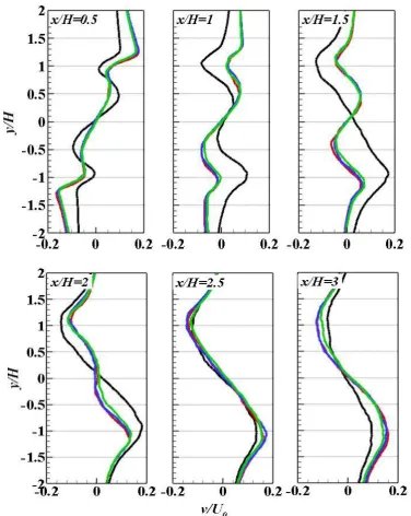
4.3.1 Velocity Components for Square Cylinders ... 86
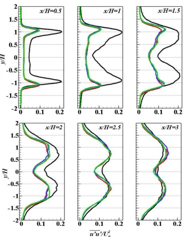
4.3.2 Reynolds Stresses for Square Cylinders ... 88
4.4 Rectangular Cylinder ... 93
4.4.1 Velocity Components for Rectangular Cylinders ... 94
4.4.2 Reynolds Stresses for Rectangular Cylinders ... 96
4.5 Drag Coefficients from Experimental Results ... 101
4.6 Conclusions ... 103
CHAPTER 5 Computational Model and Mathematical Formulations ... 104
5.1 Introduction ... 104
5.2 Bluff Body Configurations ... 107
5.3 Numerical Procedure ... 108
5.3.1 Mathematical Formulations ... 108
Porous Material ... 109
5.3.2 Shear Stress Transport (SST) Turbulence Model ... 110
5.4 Computational Model Configuration ... 113
5.5 Grid Generation ... 116
5.5.1 Mesh Structure at the Near Wall Region ... 117
5.6 Computational Setup ... 122
5.7 Solution Convergence and Mesh Independency Analysis ... 127
5.8 Model Verification through Comparison with Experimental Data ... 130
5.9 Conclusions ... 134
CHAPTER 6 Numerical Results and Discussion ... 136
6.1 Introduction ... 136
6.2 Validation of the URANS Results with Available Data ... 137
6.3 Velocity Streamlines ... 140
6.4 Vorticity Contours ... 142
6.5 Velocity Components ... 144
6.5.1 Velocity Components in the Shear Layer Region ... 145
6.5.2 Velocity Components in the Wake ... 149
6.6 Pressure ... 152
6.7 Aerodynamic Forces ... 155
6.8 Conclusions ... 158
CHAPTER 7 Conclusions and Future Work ... 160
7.1 Introduction ... 160
7.2 Key Contributions of the Research ... 162
7.3 Future Work ... 163
REFERENCES ... 166
APPENDIX A ... 182
L
IST OF
F
IGURES
Figure 2.1 A schematic of the different flow regimes for circular and square cylinders
17
Figure 2.2 A circular cylinder covered with a sheath of porous material. 25 Figure 2.3 The location of the porous treatment on a square and rectangular
cylinder commonly used in the literature. (a) a porous cover around a square cylinder, (b) porous layers around a rectangular cylinder.
29
Figure 2.4 Schematic of the blunt trailing edge flat plate with a porous section at the trailing edge (Showkat Ali et al., 2017).
30
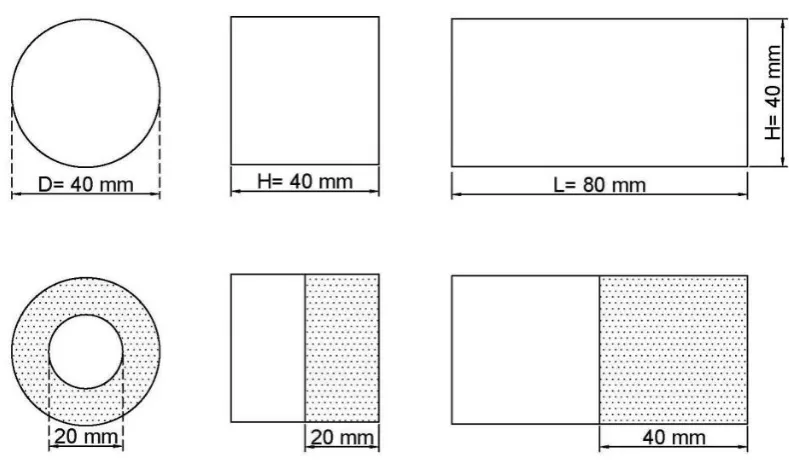
Figure 3.1 The bare circular, square and rectangular cylinders used as the references and the cylinders treated with porous materials. The circular cylinder was covered with porous materials and the square and rectangular cylinders were formed by replacing the downstream halves with porous materials.
48
Figure 3.2 The porous materials used in the experiments. 1, 2 and 3 represent the 20 PPI, 40 PPI and 60 PPI, respectively. Their characteristics are given in Table 3.1.
48
Figure 3.3 The experimental setup for the measurement of permeability of porous materials.
53
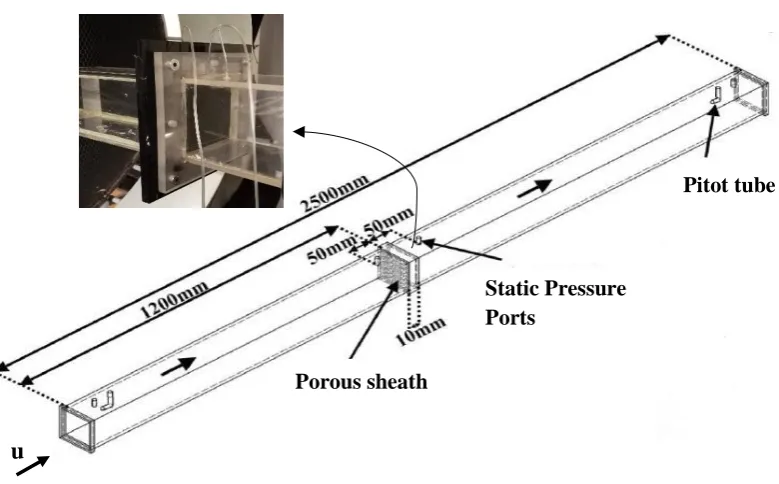
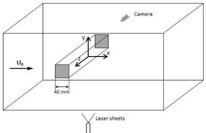
Figure 3.4 A sketch of the wind tunnel test section with a sample test model and the coordinate system with its origin at the centre of the models. The camera is positioned on the transparent side of the wind tunnel in the direction of the cross section of the models and the laser is located below the models and outside the wind tunnel.
57
Figure 3.5 The solid circular cylinder mounted in the wind tunnel. The black part in the middle is to prevent light reflection due to the aluminium reflective property.
59
Figure 3.6 The porous covered circular cylinder mounted in the wind tunnel. The porous material shown is 60 PPI.
Figure 3.7 The solid rectangular cylinder mounted in the wind tunnel. The black part in the middle is to prevent light reflection due to the aluminium reflective property.
60
Figure 3.8 The half-porous rectangular cylinder mounted in the wind tunnel. The porous material shown is 60 PPI.
60
Figure 3.9 The cross correlation procedure in PIV velocity measurement. A plot is obtained from two corresponding interrogation areas using a cross-correlation algorithm, which is then used to calculate the velocity vector.
67
Figure 4.1 Time-averaged streamline topology for circular cylinders; (a) bare cylinder, (b) cylinder covered with 60 PPI porous layer, (c) cylinder covered with 40 PPI porous layer and (d) cylinder covered with 20 PPI porous layer.
73
Figure 4.2 Mean stream-wise velocities at different axial locations from circular cylinders. black line: solid; green line: porous 60 PPI; blue line: porous 40 PPI; red line: porous 20 PPI.
75
Figure 4.3 Mean cross-stream velocities at different axial locations from circular cylinders. black line: solid; green line: porous 60 PPI; blue line: porous 40 PPI; red line: porous 20 PPI.
77
Figure 4.4 The wake width generated in the wake of solid circular cylinder and the circular cylinder treated with 20 PPI porous material.
79
Figure 4.5 Normal stream-wise Reynolds stress in the wakes of the circular cylinders. black line: solid; green line: porous 60 PPI; blue line: porous 40 PPI; red line: porous 20 PPI.
81
Figure 4.6 Normal cross-stream Reynolds stress in the wakes of the circular cylinders. black line: solid; green line: porous 60 PPI; blue line: porous 40 PPI; red line: porous 20 PPI.
82
Figure 4.7 Shear Reynolds stress in the wakes of the circular cylinders. black line: solid; green line: porous 60 PPI; blue line: porous 40 PPI; red line: porous 20 PPI.
83
Figure 4.8 Time-averaged streamlines generated by square cylinders; (a) bare cylinder, (b) cylinder treated with 60 PPI porous layer, (c) cylinder treated with 40 PPI porous layer and (d) cylinder treated with 20 PPI porous layer.
Figure 4.9 Mean stream-wise velocities at different axial locations generated by the square cylinder. black line: solid; green line: porous 60 PPI; blue line: porous 40 PPI; red line: porous 20 PPI.
87
Figure 4.10 Mean cross-stream velocities at different axial locations generated by the square cylinder. black line: solid; green line: porous 60 PPI; blue line: porous 40 PPI; red line: porous 20 PPI.
88
Figure 4.11 Normal Reynolds stress components in the wakes of the square cylinders. black line: solid; green line: porous 60 PPI; blue line: porous 40 PPI; red line: porous 20 PPI.
90
Figure 4.12 Normal Reynolds stress components in the wakes of the square cylinders. black line: solid; green line: porous 60 PPI; blue line: porous 40 PPI; red line: porous 20 PPI.
91
Figure 4.13 Shear Reynolds stress components in the wakes of the square cylinders. black line: solid; green line: porous 60 PPI; blue line: porous 40 PPI; red line: porous 20 PPI.
92
Figure 4.14 Time-averaged streamlines generated by rectangular cylinders; (a) bare cylinder, (b) cylinder treated with 60 PPI porous layer, (c) cylinder treated with 40 PPI porous layer and (d) cylinder treated with 20 PPI porous layer.
93
Figure 4.15 Mean stream-wise velocities at different axial locations from rectangular cylinder. black line: solid; green line: porous 60 PPI; blue line: porous 40 PPI; red line: porous 20 PPI.
95
Figure 4.16 Mean cross-stream velocities at different axial locations from rectangular cylinder. black line: solid; green line: porous 60 PPI; blue line: porous 40 PPI; red line: porous 20 PPI.
96
Figure 4.17 Reynolds stress components in the wakes of the rectangular cylinders. black line: solid; green line: porous 60 PPI; blue line: porous 40 PPI; red line: porous 20 PPI.
98
Figure 4.18 Reynolds stress components in the wakes of the rectangular cylinders. black line: solid; green line: porous 60 PPI; blue line: porous 40 PPI; red line: porous 20 PPI.
99
Figure 4.19 Reynolds stress components in the wakes of the rectangular cylinders. black line: solid; green line: porous 60 PPI; blue line: porous 40 PPI; red line: porous 20 PPI.
100
Figure 4.20 The control volume around the cylinder to calculate the drag coefficient based on the integral momentum equation
Figure 5.1 The square cylinders used in the numerical simulations; a) bare cylinder used as the reference, b) the square cylinder treated with 20 PPI porous material at its trailing half, c) the square cylinder treated with 20 PPI porous material at its leading half.
107
Figure 5.2 Schematic of the computational domain showing a) side view and b) top view containing the dimensions of the domain.
115
Figure 5.3 Perspective view of the model geometry in DesignModeler showing the square cylinder with its leading half comprising porous material.
115
Figure 5.4 Side view of the structured mesh generated for the bare square cylinder; a) whole domain, b) enlarged view showing the finer mesh around the cylinder.
120
Figure 5.5 Side view of the structured mesh generated for the square cylinder with porous material at its leading half: a) whole domain, b) enlarged view showing the finer mesh around the cylinder.
121
Figure 5.6 The conditions used on the boundaries of the domain encasing all the cases studied.
125
Figure 5.7 Stream-wise velocities at different axial locations in the wake region for the bare square cylinders; Black solid line: steady RANS, Orange dotted line: time-averaged experimental results.
132
Figure 5.8 Cross-stream velocities at different axial locations in the wake region for the bare square cylinders; Black solid line: steady RANS, Orange dotted line: time-averaged experimental results.
132
Figure 5.9 Stream-wise velocities at different axial locations in the wake region for the trailing-half porous square cylinders; Dark blue line: steady RANS, Red line: time-averaged experimental results.
133
Figure 5.10 Cross-stream velocities at different axial locations in the wake region for the trailing-half porous square cylinders; Dark blue line: steady RANS, Red line: time-averaged experimental results.
134
Figure 6.1 Profiles of the time-averaged stream-wise velocity at the centreline downstream the solid square cylinder. Comparison is made between the experimental results of Durão et al. (1988) and averaged numerical velocity profile of Trias et al. (2015).
Figure 6.2 Profiles of the time-averaged stream-wise velocity at x/H =-0.625. Comparison is made between the numerical results of Minguez et al. (2011) and Trias et al. (2015).
139
Figure 6.3 Profiles of the time-averaged stream-wise velocity at x/H=0.625. Comparison is made between the numerical results of Minguez
et al. (2011) and Trias et al. (2015).
139
Figure 6.4 Time-averaged velocity streamline generated by square cylinders; (a) bare cylinder, (b) cylinder treated with 20 PPI porous layer at the trailing half, (c) cylinder treated with 20 PPI porous layer at the leading half.
141
Figure 6.5 Contours of instantaneous vorticity magnitude in the wake of the square cylinders; (a) bare cylinder, (b) cylinder treated with 20 PPI porous layer at the trailing half, (c) cylinder treated with 20 PPI porous layer at the leading half.
143
Figure 6.6 Axial locations around the cylinder used in Figures 6.7 to 6.9; a:
𝑥 𝐻⁄ = −0.9, b: 𝑥 𝐻⁄ = −0.8, c: 𝑥 𝐻⁄ = −0.7, d: 𝑥 𝐻⁄ = −0.6, e: 𝑥 𝐻⁄ = −0.5, f: 𝑥 𝐻⁄ = −0.4, g: 𝑥 𝐻⁄ = −0.3, h: 𝑥 𝐻⁄ =
−0.2, i: 𝑥 𝐻⁄ = −0.1.
144
Figure 6.7 Time-averaged stream-wise velocities at different axial locations in the shear layer region for the bare and porous-treated square cylinders.
147
Figure 6.8 Time-averaged cross-stream velocities at different axial locations in the shear layer region for the bare and porous-treated square cylinders.
148
Figure 6.9 Time-averaged stream-wise velocities at different axial locations in the wake of the bare and porous-treated square cylinders.
151
Figure 6.10 Normalised time-averaged stream-wise velocity at the centreline downstream the square cylinders. Comparison is made between the bare square cylinder and the square cylinders with porous materials at their leading and trailing halves.
151
Figure 6.11 Time-averaged pressure at the mid-plane downstream the square cylinders. (a) bare cylinder, (b) cylinder treated with 20 PPI porous layer at the trailing half, (c) cylinder treated with 20 PPI porous layer at the leading half.
154
Figure 6.12 Time-averaged pressure coefficient at the centreline downstream the square cylinders. Comparison is made between the solid
square cylinder and the square cylinders with porous materials at their leading and trailing halves.
Figure 6.13 Drag and lift coefficients generated by the solid square cylinder; green line: Drag coefficient, yellow line: Lift coefficient.
156
Figure A.1 TKE content in the wake of rectangular cylinders; (a) bare cylinder, (b) cylinder treated with 60 PPI porous layer, (c) cylinder treated with 40 PPI porous layer and (d) cylinder treated with 20 PPI porous layer.
182
Figure A.2 TKE content in the wake of circular cylinders; (a) bare cylinder, (b) cylinder covered with 60 PPI porous layer, (c) cylinder covered with 40 PPI porous layer and (d) cylinder covered with 20 PPI porous layer.
183
Figure A.3 TKE content in the wake of square cylinders; (a) bare cylinder, (b) cylinder treated with 60 PPI porous layer, (c) cylinder treated with 40 PPI porous layer and (d) cylinder treated with 20 PPI porous layer.
L
IST OF
T
ABLES
Table 2.1 Compilation of the studies on the use of porous materials for flow control of a circular cylinder. The method of the investigation, flow Reynolds number (Re), the ratio of the thickness of the porous cover (h) to the diameter of the cylinder (D) are presented
26
Table 3.1 Values ofporosity and permeability of the porous materials used in the experiments
49
Table 4.1 The drag coefficients for the flow around solid bare circular, square and rectangular cylinders and circular, square and rectangular cylinders with porous materials at their trailing halves calculated by the integral momentum method.
102
Table 5.1 Mean values of drag and base pressure coefficients and the rms value of the lift coefficient for the flow around solid square cylinder.
129
Table 5.2 Base pressure coefficient and mean stream-wise velocity at
x/H=0.5 on the centreline for the flow around leading-half porous square cylinder.
130
Table 5.3 Base pressure coefficient and mean stream-wise velocity at
x/H=0.5 on the centreline for the flow around trailing-half porous square cylinder.
130
Table 6.1 Mean values of pressure coefficient for the solid bare square cylinder and square cylinders with porous materials at their trailing and leading halves. From left to right:pressure coefficient at the front point, pressure coefficient at the base point, minimum pressure coefficient in the wake. Results of Minguez et al. (2011) for a solid bare cylinder is included as a comparison to the present work.
153
Table 6.2 The time-averaged drag coefficient and rms value of fluctuations in the lift coefficient for the flow around solid bare square cylinder and square cylinders with porous materials at their trailing and leading halves. Results of Minguez et al. (2011) for a solid bare cylinder is included as a comparison to the present work
N
OMENCLATURE
L
IST OF
S
YMBOLS
𝑨
Cross sectional area [m2]C
Quadratic loss coefficient𝑪
𝒅 Drag coefficient𝒄
𝒇 Skin friction coefficient𝑪
𝒍 Lift coefficient𝑪
𝒑 Pressure coefficient𝑪
𝒑,𝒃 Base pressure coefficient𝑪
𝒑,𝒇 Front pressure coefficientD
Diameter of circular cylinder [m]𝒇
Frequency [Hz]𝑭
𝑫 Drag force [N]𝑭
𝑳 Lift force [N]𝒌
Turbulent kinetic energy [m2/s2]𝑳
Distance [m]𝑳
𝒓 Recirculation length [m]𝑷
Pressure [Pa]𝑸
Volumetric flow rate [m3/s]𝒔𝒕
Strouhal numbert
Time [s]𝒖
Velocity component in the x direction [m/s]𝒖
𝒄 Velocity component in the x direction on the centreline [m/s]𝑼
𝟎 Free-fluid velocity [m/s]𝑼
𝝉 Frictional velocity [m/s]𝒖
′𝒖
′ Normal Reynolds stress in the x direction [m2/s2]𝒖
′𝒗
′ Shear Reynolds stress [m2/s2]𝒗
′𝒗
′ Normal Reynolds stress in the y direction [m2/s2]x, y, z
Cartesian coordinates𝒚
+ Non-dimensional wall adjacent cell distance𝜺
Turbulent dissipation rate [J/kg.s]𝜿
Permeability [m2]𝝁
Dynamic fluid viscosity [N.s/m2]𝝆
𝒑 Particle density [kg/m3]∅
Porosity𝝉
𝒘 Wall shear stress [N/m2]𝝂
Kinematic viscosity [m2/s]A
BBREVIATIONS
CFD
Computational Fluid DynamicsPPI
Pore per inchRANS
Reynolds Averaged Navier-StokesRe
Reynolds numberSST
Shear Stress TransportTKE
Turbulent Kinetic EnergyC
HAPTER 1
INTRODUCTION
1.1Background
To control the drag, vibration and noise, the sources causing the instabilities, i.e. the separated flow in the wake region and the dynamics of the vortex formation have to be controlled. Such control can be achieved by using different flow control techniques broadly classified as active and passive methods. Active control is typically achieved by making perturbations in the wake flow through some excitation mechanism, for example rotational oscillations of the body (Choi and Choi 2002), flow forcing (Naim et al. 2007) and blowing and suction of fluids through surfaces (Huang et al. 2004). Passive methods include making modifications to the surface by introducing roughness (Park et al. 2011), the use of riblets (Greidanus et al. 2015), changing the geometry of leading or trailing edges (Lyu and Azarpeyvand 2017) and so on. Passive methods have recently been the subject of many studies. These methods are preferred over active control methods due to the simplicity in their application, independence from an external energy source and relatively low cost.
1.2Problem Statement
The literature survey reveals that there is very limited work on flow over porous bluff bodies most of which has been done numerically. Much of the preceding work on this topic has been directed to covering a bluff body with a porous layer (Bhattacharyya and Singh 2011, Rong et al. 2011). The majority of these studies are on circular cylinders wrapped with a porous sheath (Liu et al. 2012, Naito and Fukagata 2012). In particular, the following gaps have been identified: experimentally determined benchmarks, three-dimensional numerical studies, investigation on the effect of porous treatment on different configurations and the effect of the disposition of the porous treatment on a particular configuration. Therefore, this thesis addresses the above mentioned gaps through developing a novel passive method to control the wake instabilities and therefore reducing the induced drag and vibrations.
1.3Research Objectives
The main objective of this research is to control the flow around a bluff body by substituting a part of a solid body with a porous medium. The idea is to modify the shear forces in order to regularise the flow and to reduce the induced drag.
In this project, firstly the flow over bluff bodies of widely encountered cross sections, namely circular, square and rectangular are experimentally studied. The effect of porous material with a range of porosities on the flow structure in the wake of cylinders are investigated. Subsequently, simulations are performed over three-dimensional solid and porous square bluff bodies. Comparisons with the experimental results and previous work will serve to refine and validate the chosen numerical method. Studying the formation of the boundary layer form an integral component of the study. Knowledge of the boundary layer formation is critical for drag control.
1. Perform experiments on the flow over solid and porous bluff bodies over a range of parameters including the physical characteristics of porous media and geometries.
2. Evaluate and validate a numerical method for simulating the flow over porous bluff bodies.
3. Perform simulations to investigate the effect of disposition of the porous medium on the boundary layer, drag coefficient and flow structure in the wake of porous bluff bodies.
1.4Research Methodologies and Techniques
To achieve the objectives enumerated in section 1.3, a step-by-step approach was followed in this research. These steps are summarised in the following.
Step 1 - Literature review on passive flow control by means of porous
material
literatureafocusedaonaknowledgeagaps yetatoabeaaddressed and possible future work in this field of porous flow control.
Step 2 – Performing experiments on solid and porous-treated bluff bodies
Following the investigations of the literature concerned with the use of various porous materials on bluff body configurations, three configurations have been selected for the experimental studies. Circular cylinders were to be covered with a porous sheath, while porous sheaths would replace the downstream halves of the square and rectangular cylinders. Prototypes of the proposed porous-coated bluff bodies were developed based on the characteristics of the system discovered in the literature review. The bluff bodies were selected to be fabricated from aluminium material. The porous media consisted of open cell polyurethane material, selected with three permeabilities. The total size of the prototypes remained the same in all the experiments. In the first set of experiments, the flow over bluff bodies completely consisted of aluminium was investigated. In the second set of experiments, half the size of the bluff bodies consisted of aluminium and the other half was composed of porous material of a distinct permeability.
wake of the cylinders using an adaptive cross-correlation method. The results were used to determine the flow field in the wake of the bluff bodies as well as velocity profiles and Reynolds stresses.
Step 3 –ANSYS simulation modelling the bluff bodies treated with porous
media
Once the experimental investigations on the application of porous media to three configurations was completed, further investigations have been performed through numerical studies. Due to the extensive numerical studies on circular cylinders covered with a porous layer, this configuration was not considered for numerical investigations in this work. Moreover, according to the experiments, similar effect of porous material has been observed for the square and rectangular cylinders. Therefore, the studies was continued on the square cylinder to obtain a deeper understanding of the flow in the presence of porous material beyond what has been obtained from experiments.
Among the porous materials used in the experiments, the highest effect on the flow control has been achieved with the highest permeability material. Therefore, the material with the highest permeability was employed in the simulations to show more tangible differences between the flow over the solid cylinder and porous-treated cylinder. Research has been dedicated to investigate the effects of the location of porous layer on the flow structure and aerodynamic performance of the bluff bodies. For this purpose, the system was modelled and simulated using ANSYS CFX. Three-dimensional studies of the bluff bodies were conducted using a structured grid.
equations, which are typically intractable to analytic techniques. The Navier-Stokes equations describe the momentum of the fluid, which is a balance between external forcing, internal inertial effects, and internal dissipative effects. To consider the details of the flow through the pore structure of porous media is computationally infeasible. Therefore, a numerical solution to the problem is sought, so that the flow behaviour in the three regions can be accurately described. Coupling the Navier-Stokes equations with Darcy or Brinkman equation, representing the porous material, is one method. However, accurate modelling of the interface between the fluid and porous material is still an unsolved challenge in this method. The volume penalisation is another method, which is easy to implement and overcomes the difficulties of coupling the equations governing fluid flow in the unobstructed and porous regions.
determined. In addition, velocity profiles around the obstacles and in the near wake and far wake have been presented.
1.5Research Contribution to Knowledge and Statement of Significance
1.5.1 Academic Contribution
The contribution of this project to knowledge is that it provides a step towards understanding the flow over bluff bodies modified with porous materials. In studies on fluid flow over porous-treated bluff bodies of basic geometries, the porous treatment is commonly considered as a cover on the bluff body (Takeshi et al. 2010, Rashidi et al. 2013). The novelty in the present work is that new porous treatments have been considered in which regions of solid cylinders were replaced by porous materials. The significance of this project is that it extends previous studies by considering the effect of the replacement of a part of a bluff body with porous materials, which determines the efficacy of the porous treatment in the control of flow over bluff bodies. The transport of fluid flow around uncontrolled and controlled bodies of circular, square and rectangular cross-sections is examined by conducting a series of experiments. In the experiments, the effect of porous layer permeability, on the topology of the flow field and downstream velocity and turbulence distribution is investigated.
Furthermore, the position of the porous material on a square cylinder is changed from being the trailing edge to the leading edge and the effect of such disposition on a range of phenomena related to flow control is examined. The phenomena include the flow field, vorticity and pressure distribution, the flow field structures adjacent to the porous layer and within the boundary layer and downstream velocity and turbulence. The effect of different arrangements of porous layer on the drag force is also investigated.
Overall, this research contributes to existing knowledge because it:
Provides experimental data and a mathematical model on a novel porous treatment
for different configurations of bluff bodies. It is anticipated that the experimental data will be very useful to theoreticians and numericists who are required to evaluate their mathematical models.
Demonstrates how the permeability of porous media affects the flow fields around
the bluff bodies that have been studied. This is important because it is one of the key variables over which designers and research have control.
Provides for the first time the importance of the physical configuration of porous
media on bluff bodies. For example, it is shown that the flow fields developed over bluff bodies that have been modified by placing porous media on their leading edge are significantly different from those on which porous media form their trailing edge.
The work provides a rich source of data and deep insights into the nature of the
1.5.2 Practical Contribution
Fuel consumption of transportation vehicles is directly proportional to the drag coefficient (Browand 2005). Porous media have the capacity to reduce the drag coefficient and hence the judicious use of porous media has the capacity to reduce fuel consumption. A large component of the fuel consumption of a vehicle arises in overcoming the aerodynamic drag, particularly in the case of large vehicles travelling at high speeds. For example, about 20% of fuel in a medium-size sedan is consumed to overcome aerodynamic drag at 100 km/h and this amount can increase to 50% for a heavy commercial vehicle (Wang et al. 2016). A reduction in aerodynamic drag by 15% at highway speed of 88 km/h can lead to a saving in fuel by about 5 to 7 % (Browand 2005, Bellman et al. 2010). In addition, fuel consumption by ground vehicles accounts for over 30% of CO2 and other greenhouse gas emissions (Sudin et al. 2014). Therefore, a
reduction in the aerodynamic drag is significant to improve the fuel economy and reduce greenhouse gas emissions. In this regard, a novel method is proposed to controlafluidaflowsaover the vehicles. Currently the technologies and approaches employed for the purpose of drag reduction are expensive and not necessarily efficient. The current approach used on, for example road vehicles, is to streamline the overall shape of the bluff body (Minguez et al. 2008). Streamlining reforms all the blunt, angled surfaces of the body to smooth, more gradually changing surfaces so that the fluid can easily flow over the body. The detached flow imposed to vehicles can be decreased by such transformation. However, dynamic stability will be negatively affected and complexities will be added to the model.
porous medium will decrease the drag forces by creating an intermediate flow, which reduces the shear forces. The porous coating can removeatheaproblemsacausedabyathe existing flowacontrolamethods suchaasainstabilityaandacomplicated design. Apartafrom fuelaconsumption,alifetimeaofavehicleais ofahigh importance.aFluid flowaoverathe bluffabodyaimposesaforcesaagainstatheadirectionaofatheabodyaleadingatoaerosion and decreaseathealifetime of theaobject (Lienhart et al. 2002). Takingaadvantage of the proposed treatment, wearaandatearadiminishesatheadegreeaofadecay andadeterioration, whichainaturnaincreasesathealifetime of theadevicesaandareducesacosts.
1.6Thesis Structure
Following the literature review andatheadetectionaof thearesearch field, Chapter 3 provides details on the experimental procedure and fundamentals of the experimental method. Details of the bluff body configurations, namely circular, square and rectangular cylinders, characteristics of porous materials and equipment used are described. Chapter 4 contains the results of the experiments, including the velocity field and flow structures in the wake of the cylinders not treated with porous material. In addition, the results of the porous treated configurations are presented in comparison with the solid bare cases. The chapter also includes a full discussion on the effects of different porous materials on the flow structure.
C
HAPTER 2
LITERATURE REVIEW ON FLOW CONTROL OVER BLUFF
BODIES USING POROUS TREATMENT
2.1Introduction
Bluff, non-streamlined, bodies are ubiquitous in nature. They include buildings, communications towers, dampers in air conditioning valves, air conditioning registers for admitting and ejecting air from rooms, motor vehicles, components in heat exchangers, chemical reactors and so on. Flow over bluff bodies immersed in a fluid has motivated considerable research for decades. The problem arises when the body moves relative to the fluid, and vortices are generated in the wake downstream of the body. The vortices increase induced drag forces, which act in the direction opposite to the relative motion of the body. Drag forces can give rise to large unsteady forces that have the potential to reduce the structural integrity of the bluff body or to decrease its hydro-dynamical or aero-dynamical effectiveness.
shedding frequency when designing offshore structures. Roshko (1954) was the first to measure the period of Karman vortex shedding behind a bluff body after whom many researchers investigated the vortex shedding and near-wake flow. Gerrard (1966) has described the mechanism behind the formation of vortex streets for short bluff bodies such as circular and square cylinders. He discusses that alternate vortices in the wake of the bodies are formed as a result of the interaction of the separated shear layers when drawing into the growing vortex. This idea was later verified through the experiments of Green and Gerrard (1993). The studies regarding the vortex shedding in the wake of bluff bodies are extensively analysed in the literature, for example, reviewed by Lin and Pao (1979), Bearman (1984), Oertel (1990), Coutanceau and Defaye (1991), Griffin and Hall (1991), Williamson (1996), Williamson and Govardhan (2004).
Among the types of bluff objects studied in fluid dynamics research, cylindrical bodies have been the topic of particular attention. Cylinders with circular, square and rectangular cross sections have been investigated in order to understand the fundamental physics involved in the dynamics of the wake. The wake of a fluid passing a cylinder exhibits distinct behaviours depending on the cross-section of the cylinder and the flow Reynolds number (Re), which represents the ratio of inertia force to viscous force in the flow. For a cylinder with a circular cross-section, in very low Reynolds numbers (𝑅𝑒 <
cylinder. The separation point changes according to the conditions of the incoming flow and the boundary layer developed on the surface of the cylinder.
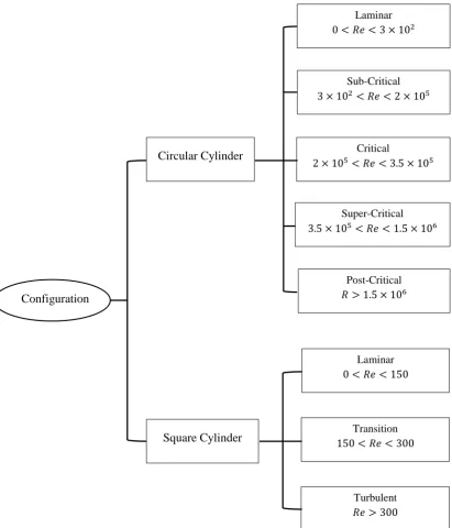
Different flow regimes have been defined for a circular cylinder based on the Reynolds number, where the flow experiences boundary layer transitions (Williamson 1988, Schewe 2006, Sumer and Fredsøe 2006). For Reynolds numbers from zero up to 3×10², the flow undergoes a transition from being very attached to the surface to a periodic laminar wake, where vortex shedding forms. In Reynolds numbers between 3×10² and 2×10⁵ the flow is sub-critical, where the laminar wake is replaced by turbulent
instabilities with an almost unchanged wake topology in this range. The wake at the sub-critical regime is fully turbulent while the boundary layer remains laminar. The sub-critical regime occurs in Reynolds numbers from 2×10⁵ to 3.5×10⁵ with major changes in the flow structure, such as the emergence of asymmetries in the wake and an abrupt reduction in the drag coefficient. The flow is super-critical when the Reynolds number lies between 3.5×10⁵ and 1.5×10⁶, at which the flow recovers its symmetry in the wake and the drag coefficient remains almost unchanged throughout the entire range. Higher Reynolds numbers put the flow in a post-critical regime. A comprehensive review of the above regimes can be found in Zdravkovich (2003).
Higher Reynolds numbers induces an irregular regime with velocity fluctuations showing distinct irregularities in the cylinder wake (Roshko 1954, Bloor 2006). A schematic of the above regimes for the circular and square cylinders is illustrated in Figure 2.1.
Figure 2.1. A schematic of the different flow regimes for circular and square cylinders
Laminar
0 < 𝑅𝑒 < 3 × 10²
Post-Critical
𝑅 > 1.5 × 10⁶
Super-Critical
3.5 × 10⁵< 𝑅𝑒 < 1.5 × 10⁶
Sub-Critical
3 × 10²< 𝑅𝑒 < 2 × 10⁵
Critical
2 × 10⁵< 𝑅𝑒 < 3.5 × 10⁵
Circular Cylinder
Turbulent
𝑅𝑒 > 300
Transition
150 < 𝑅𝑒 < 300
Laminar
0 < 𝑅𝑒 < 150
The aspect ratio (L/H) in a rectangular cylinder, where L is the width along the direction of flow and H is the height of the cross-section, plays an important role in determining the vortex formation and the hydrodynamic forces on the body. The aspect ratio and the flow Reynolds number determine whether the flow over the rectangular cross section is separated or reattached, which depends on the reattachment of the shear layer on the surfaces of the cylinder parallel to the free-stream flow hereinafter called side surfaces (Okajima 1982). In the separated flow case, the flow separates at the upstream edge of the cylinder and remains separated along the side surfaces, i.e. no reattachment happens for the shear layer. Therefore, the separation bubble covers the entire side surface. In the reattached case however, the flow reattaches to the surface at a certain point along the side surfaces with a possibility of another separation further downstream the sides. For an aspect ratio equal to L/H=2, Okajima (1982) found that the flow undergoes a transition from a reattached to a separated condition at a Reynolds number around 500 based on the free stream velocity and the height of the rectangular cylinder. However, at higher aspect ratios, the transition from an attached condition to a separated one may occur at higher Reynolds numbers or the flow remains reattached to the side surfaces. The study of the flow over rectangular cylinders with different side ratios and over a range of Reynolds numbers can be found in the literature for example, studies in the range of 1 < 𝐿/𝐻 < 4 and 70 < 𝑅𝑒 < 2 × 10⁴ by Okajima et al. (1990), 0.6 <
𝐿/𝐻 < 8 and 𝑅𝑒 = 2.2 × 10⁴ by Shimada and Ishihara (2002) and 2 < 𝐿/𝐻 < 3 and
𝑅𝑒 = 2 × 10³, 2 × 10⁴ by Kuroda et al. (2007).
idea of shear layers alteration has been widely applied in the control of flow over bluff bodies. Examples of such alterations are the use of roughness on the surfaces (Park et al. 2011), serrations (Shi et al. 2012) and a secondary control cylinder (Liu et al. 2015). An extensive review of the studies with the aim of changing the vortex street to decrease the drag force and fluctuating lift force can be found in the work of Choi et al. (2008).
2.2Flow Control Techniques
The fundamental occurrence of flow over bluff bodies and the problem of attenuation of vortex shedding, lift and drag fluctuations and noise generation have been an important subject of study for years (Fink and Bailey 1980, Robinson 1991, Choi and Choi 2002, Naito and Fukagata 2012). Efforts have been made to modify and suppress vortex shedding by means of various control methods such as active and passive techniques. Passive methods have been a recent focus of attention to control the flow over bluff bodies and reduce drag due to their relative simplicity, durability and less cost compared to active methods. In passive methods, flow is manipulated by the changes in the geometry of the body without using extra energy. The use of compliant walls that mimic the properties of the skins of dolphin (Carpenter et al. 1999, Wiplier and Ehrenstein 2000), riblets (Walsh 1983, Robinson 1991, García-Mayoral and Jiménez 2011, Greidanus et al. 2015), rough surfaces (Park et al. 2011) and splitter plates (Vu et al. 2016, Sarioglu 2017) are examples of passive methods.
Reduction of pressure fluctuations allows the flow to penetrate the pores, which promotes local blowing and suction (Choudhari and Khorrami 2003). The flow leakage across the porous surface modifies the local mean flow structures. The use of porous material is not restricted to the flow control. It is also used for the enhancement of heat transfer (Liebenberg and Meyer 2007). There has been considerable published research in the field of convection heat transfer within porous media (Perng et al. 2011, Sauret et al. 2014, Rees 2015). The wide range of published work (for example Pop and Ingham 2001, Vafai 2005, Nield and Bejan 2014, Hooman et al. 2017) indicates the level of understanding of momentum and heat transport in porous media.
2.3Mathematical Formulations for Porous Materials
Porous materials or porous media form a class of materials containing voids or pores, typically filled with a fluid. Porous media can be found everywhere from rocks and soils to woods and bones and manufactured materials such as cements or foams. Porous materials are generally characterised by their porosity (∅), which is an indication of the ratio of the pore volume to the total volume of the material and assumes a value between 0 and 1. Porosity has a significant impact on the mechanical, physical, and chemical
properties of the materials. Other basic parameters related to the pores such as the pore size, shape, and surface area have indeed an important role in the functionality of a porous media. The ability of a porous material to pass a fluid through is determined by a parameter called permeability (𝜅). The SI unit of permeability is m2, but darcy is also
which is a non-dimensional quantity defined as the permeability over the square of a characteristic length, usually particle diameter,
𝐷𝑎 = 𝜅
𝑑2. (2.1)
Porous materials are also known with other properties, which are governed by the geometrical and mechanical properties of the material. Such properties include tortuosity, thermal permeability, thermal viscous characteristics, surface roughness and so on (Lu et al. 1999). Porous media arise in many areas of science and engineering such as filtration, geo-mechanics, petroleum engineering, biology and material science. Porosity and permeability of porous materials have been demonstrated to be the most important parameters for flow-porous vortex structure interaction when porous materials are used as a mean to control the flow around bluff bodies (Rashidi et al. 2013, Showkat Ali et al. 2017). Fluid flow through porous media has attracted considerable research over the last few decades and many formulations have been developed to explain and quantify the flow through porous materials. The formulations are presented in sections 2.3.1 and 2.3.2.
2.3.1 Darcy’s Law and Brinkman Model
Darcy was the first who determined a model to describe the flow through a porous medium known as Darcy’s law. In the Darcy model, the flow discharge rate is proportional to the pressure gradient via the relation (Bear 1972, Rajagopal 2007):
𝜇
where, 𝑈 is the superficial velocity inside the porous medium, ∇𝑝 is the pressure gradient along the porous material, 𝜇 is the viscosity of the fluid and 𝜅 is the permeability of the porous medium. Darcy's law is valid for laminar flow through sediments. The Darcy model is a simple model and has hitherto been the most widely used model for porous material flow.
Brinkman added an effective viscosity term to the Darcy model to combine the Darcy flow and viscous Stokes flow (Brinkman 1947) as,
𝜇
𝜅𝑈 = −∇𝑝 + 𝜇̃∆𝑈, (2.3)
with 𝜇̃ representing the Brinkman effective viscosity. The Brinkman model makes it possible to retain continuity of the velocity profile at the interfaces of porous media that may have permeabilities in the range 0 ≪ 𝜅 ≪ ∞.
2.3.2 Darcy–Forchheimer Law
For flows in porous media with Reynolds numbers greater than 1, the significance of inertial effects has to be taken into account, as the fluid velocity in the pores becomes significant (Vafai and Tien 1981). Therefore, an inertial term, known as the Forchheimer term, has been added to the Darcy's equation, which accounts for the non-linear behaviour of the pressure gradient. The Darcy-Forchheimer model reads (Bejan 1984)
𝜇 𝜅𝑈 +
𝜌
𝜅1𝑈2 = −∇𝑝, (2.4)
where 𝜅1 denotes inertial permeability. It was shown by Costa et al. (1999) that the Forchheimer model remains valid for sufficiently high Reynolds number when they studied the effect of inertial forces on the flow behaviour in highly porous structures. The authors showed that the model is valid even when convective non-linearities affect the momentum transport at the pore scale. Fourar et al. (2004) also demonstrated that the Forchheimer model can reasonably describe the flow at high Reynolds numbers after a critical value from which Darcy’s law is no longer valid.
2.4Porous Treatment for Different Configurations
There is a series of research on the flow around and through configurations solely comprising porous material. Examples are studies on a porous circular cylinder (Noymer et al. 1998, Bhattacharyya et al. 2006, Peng et al. 2011), a porous square cylinder with zero angle of incidence (Jue 2004, Bhattacharyya et al. 2006, Chen et al. 2008, Yu et al. 2010), a porous square cylinder with an angle of incidence equal to 45o (Valipour et al. 2014), porous trapezoidal cylinder (Chen et al. 2009) and a porous sphere (Neale et al. 1973, Adler 1981, Peng et al. 2012). Moreover, flow over configurations in which porous material formed a component of their structure has been investigated. The widely studied configurations and the porous materials applied are summarised in the following sub- sections. This section aims at providing an overview of the present porous treatments for the control of flow over bluff bodies, the different configurations used and the available data. A comprehensive discussion on the studies is presented in sections 2.5.1 and 2.6.
2.4.1 Circular Cylinders
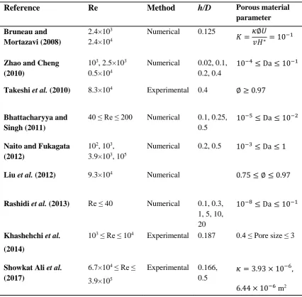
Therefore, the changes reported in the flow statistics are not the sole result of applying the porous cover.
Some of the studies regarding porous-covered circular cylinders directed at the control of the flow are listed in Table 2.1. The method on which the study has been performed including numerical and experimental, the operating flow Reynolds number (Re), the ratio of the thickness of porous cover to the diameter of bare cylinder (h/D), and a parameter related to the porous material pointed in the corresponding study are presented. The permeability coefficient (K) used in the work of Bruneau and Mortazavi (2008) is the non-dimensional coefficient of permeability based on the permeability of the porous material (𝜅), porosity (∅), flow mean velocity (U), kinematic viscosity of the fluid (𝑣) and the height of the domain (H*).
Table 2.1 Compilation of the studies on the use of porous materials for flow control of a circular cylinder. The method of the investigation, flow Reynolds number (Re), the ratio of the
thickness of the porous cover (h) to the diameter of the cylinder (D) are presented.
Reference Re Method h/D Porous material
parameter
Bruneau and Mortazavi (2008)
2.4×10³ 2.4×10⁴
Numerical 0.125
𝐾 =𝜅∅𝑈
𝑣𝐻∗ = 10−1
Zhao and Cheng (2010)
103, 2.5×10³ 0.5×10⁴
Numerical 0.02, 0.1, 0.2, 0.4
10−4≤ Da ≤ 10−1
Takeshi et al. (2010) 8.3×10⁴ Experimental 0.4 ∅ ≥ 0.97
Bhattacharyya and Singh (2011)
40 ≤ Re ≤ 200 Numerical 0.1, 0.25, 0.5
10−5≤ Da ≤ 10−2
Naito and Fukagata (2012)
102, 103, 3.9×10³, 105
Numerical 0.2, 0.5 10−3≤ Da ≤ 1
Liu et al. (2012) 9.3×10⁴ Numerical 0.75 ≤ ∅ ≤ 0.97
Rashidi et al. (2013) Re ≤ 40 Numerical 0.1, 0.3, 1, 5, 10, 20
10−8≤ Da ≤ 10−1
Khashehchi et al.
(2014)
103 ≤ Re ≤ 104 Experimental 0.187 0.4 ≤ Pore size ≤ 3
Showkat Ali et al. (2017)
6.7×10⁴ ≤ Re ≤ 3.9×10⁵
Experimental 0.166, 0.5
𝜅= 3.93 × 10⁻⁶, 6.44 × 10⁻⁶ m2
discrepancy. In some studies, the drag coefficient is found to be inversely related to the porous cover thickness (Bruneau and Mortazavi 2008,Bhattacharyya and Singh 2011), while others reported an increase in the drag coefficient (Zhao and Cheng 2010, Showkat Ali et al. 2017). However, the effect of porous thickness on the flow structures found to be dependent on the flow Reynolds number and properties of porous materials. For example Zhao and Cheng (2010) investigated the reduction in lift coefficient in a range of Reynolds numbers and Darcy numbers and found that there is a critical Darcy number at which the lift coefficient is minimum. The critical Darcy number is found to be dependent on the Reynolds number, the porous layer thickness and Forchheimer coefficient. It can be inferred that a parametric study is only beneficial when porous material is applied in a particular application to achieve the optimum parameters of interest.
2.4.2 Square and Rectangular Cylinders
is three-dimensional, therefore the reported value may not be reliable. The authors also used porous layers for a rectangular cylinder on the surfaces parallel to the free-stream flow (Bruneau and Mortazavi 2008). They used a ratio of h/H = 0.05 and 0.1, where (h) is the thickness of the porous layer and (H) is the size of the rectangle side perpendicular to the incoming flow. Their numerical investigations have been performed at the same Reynolds numbers as their previous work and over a range of permeability coefficient to conduct a parametric study. However, they only reported a regularisation in the flow by presenting lift coefficient and a vorticity parameter. The evolution of the wake structures and the mechanism of such regularisation have not been studied. Moreover, in both studies the manipulation of the interface of porous material and fluid flow has not been discussed.
In another numerical investigation by Rong et al. (2011), porous covers have been used around a square cylinder at Reynolds numbers between 20 and 200. A Darcy number range of 10-6 to 10-2 has been used for the porous covers at h/H = 0.1, 0.15 and 0.2. The study showed a dependency of drag and lift coefficients on Darcy number. Again, no data on the velocity components and turbulent intensities in the wake of the cylinder were presented. More recently, Showkat Ali et al. (2016) experimentally investigated the same topic of the effect of porous covers around square cylinders. They used two different porous materials having permeabilities equal to 𝜅 = 3.93×10⁻⁶ and 𝜅 = 6.44×10⁻⁶ with a ratio of h/H = 0.166 and 0.5. The flow was examined at Reynolds numbers from 6.7×10⁴ to 3.9×10⁵ to discover the optimum parameters for the best flow control. This study
content and Reynolds shear stress components are also presented qualitatively, but not quantitatively. Therefore, the reported reduction in the energy content and stresses cannot be quantified.
Figure 2.3. The location of the porous treatment on a square and rectangular cylinder commonly used in the literature. (a) a porous cover around a square cylinder, (b)
porous layers around a rectangular cylinder.
2.4.3 Configurations with Blunt Trailing Edges
and trailing edge surfaces of the airfoil and reduces the aerodynamic noise by creating a pressure release mechanism similar to that which occurs in the trailing edge of an owl feather (Lockhard and Lilley 2004). However, the studies show that porous material on the trailing edge can cause significant reduction in the lift force (Herr et al. 2014). Therefore, an optimised treatment is essential not to compromise the aerodynamic performance of airfoils in the interest of reducing the noise.
Figure 2.4. Schematic of the blunt trailing edge flat plate with a porous section at the trailing edge (Showkat Ali et al. 2017).
2.5Mathematical Formulations for the Modelling of the Flow Around and
Through Porous Materials
differential equations. Two main methods have been reported to model the fluid flow in configurations containing free fluid, porous layer and solid body domains. One method is to couple the Darcy or Brinkman equation, for flow in a porous medium, with the Navier–Stokes equations, and the other method is the addition of a sink term to the Navier–Stokes equations to represent all the domains.
The primary difficulty in the coupling of the Darcy or Brinkman equation with the Navier–Stokes equations is modelling the interface between the porous medium and the free fluid, which remains a somewhat unresolved problem. One of the proposed models is an empirical relation for the interface given by Beavers and Joseph (1967). The authors assumed that the flow velocity in the porous interface changes from the Darcy velocity in the porous medium (U) to the slip velocity at the interface (ui). They also presumed that
the slip velocity for the fluid is proportional to the shear rate at the interface, and expressed the free flow velocity as:
𝜕𝑢 𝜕𝑦=
𝛼
𝜅1/2(𝑢𝑖 − 𝑢𝑝); 𝑣 = 0, (2.5)
One particular example is the volume penalisation method, introduced by Arquis and Caltagirone (1984) for flows in porous media, which uses the Brinkman–Darcy drag force as a penalisation term. Due to this analogy, the method is sometimes called Brinkman penalisation. The Brinkman-Navier-Stokes equation is written as
𝜕𝑡𝑈 + (𝑈. ∇)𝑈 −
1 𝑅𝑒∆𝑈 +
𝑈
𝐾+ ∇𝑝 = 0, (2.6)
in which,
𝐾 =𝜅∅𝑈
𝑣𝐻∗, (2.7)
where ∅ is the porosity of the porous medium, 𝑈 is the mean velocity and 𝐻∗ is the height of the domain and Re is the Reynolds number based on the mean velocity of the fluid and the height of the domain.
Another example is the macroscopic momentum equation developed by Hsu and Cheng (1990) assuming that the porous material consists of mono-dispersed spherical particles:
𝜕𝑡𝑈∗+
(𝑈∗. ∇)𝑈∗
∅ − 1
𝑅𝑒∇2𝑈∗+ ∇𝑝 + 𝐾∗ = 0, (2.8)
where 𝑈∗ is the macroscopic velocity inside the porous medium and 𝐾∗ is given as
𝐾∗ = ∅𝑈∗ 𝑅𝑒 𝐷𝑎+ 𝑏 √𝑎 1 √𝐷𝑎 𝑈∗|𝑈∗|
where a and b are Ergun constants (Ergun 1952), which can be modified according to the porosity and structure of the porous material.
2.5.1 Implementation of the Mathematical Formulations and Numerical
Modelling
Numerous researchers modelled the flow interaction with porous walls by fully resolving the porous medium (Larson and Higdon 1986, Durlofsky and Brady 1987, Hsu and Cheng 1990, Vafai and Kim 1990, Kladias and Prasad 1991, Chen and Chen 1992). In particular, the effect of porosity and permeability of porous materials has been extensively studied by the use of numerical techniques. The techniques include the boundary integral method (Larson and Higdon 1986, Larson and Higdon 1987), finite element method (Snyder and Stewart 1966), finite difference method (Schwartz et al. 1993), Lattice Boltzman method (Cancelliere et al. 1990, Succi et al. 1991) and Lattice gas automata method (Rothman 1988, Kohring 1991).
Darcy number. Bhattacharyya and Singh (2011) used a penalisation technique to model the wake of a porous-wrapped circular cylinder placed in a laminar flow at Reynolds numbers between 40 and 200 (40 ≤ Re ≤ 200). They concluded that the use of porous coating for circular cylinders lead to significant reduction of drag, control of vortex shedding and dampening of the structure oscillations compared to a bare cylinder.
the use of porous covers. They also showed that when the flow is fully turbulent, a wide region of low energy is generated in the near-wake of a porous-covered cylinder, which indicates the stabilisation of the fluctuating flow field.
observed a drag reduction for the downstream cylinder, while an increase in drag coefficient was resulted for the upstream cylinder.
There also exist numerical studies on the flow over other configurations using porous treatments. A study of the flow over a two-dimensional square cylinder with a porous coating was carried out by Bruneau and Mortazavi (2004). The authors used the Brinkman volume penalisation method and found a 30% reduction in drag in the presence of porous coating. In another study by the same authors (Bruneau and Mortazavi 2008) the Brinkman penalisation method was used to simulate the flow inside fluid and porous regions around a rectangular cylinder and two Ahmed bodies with square back and with a rear window. The authors implemented a porous layer between a bluff-body and a fluid, to alter the characteristics of the boundary layer and found a dramatic regularisation of the flow, particularly at high Reynolds numbers. They found the highest drag reduction by 40% for the square back Ahmed body when changing the location of the porous layer around the body. Reduction in pressure gradient in the near wake region by up to 67% was another finding of their research. Rong et al. (2011) also numerically studied the flow over a porous covered square cylinder using Lattice Boltzman Method. They found that at Da ≥ 10−4, the increase in the thickness of the porous cover levels up the drag and lift coefficients. However, at Da ≤ 10−4, no significant effect on the drag and lift coefficients has been observed by the increase in the porous layer thickness.