Fabrication and characterization of porous opaque PMMA foils to
be laser irradiated producing ion acceleration
Mariapompea Cutroneo1,2*)
1Nuclear Physics Institute, AS CR, 25068 Rez, Czech Republic
2Department of Physics and Earth Sciences, Messina University, V.le F.S. d’Alcontres 31, 98166 S. Agata, Messina, Italy
Abstract. In this study, the effect of pore size in the opaque poly(methyl methacrylate) and its composition is investigated by optical measurements as well as Rutherford Backscattering Spectroscopy and Elastic Recoil Detection Analyses. The enhancement of the absorption coefficient induced by the presence of micrometric beads makes these porous thin foils high absorbent to IR radiation and suitable to be laser irradiated in order to generate a hot plasma rich in proton emission. The presented results indicate that the high optical transparency of PMMA foils can be strongly reduced by the presence of the micrometric acrylic beads and that the presence of high Z-metallic nanoparticles, such as gold, embedded in the polymer enhances the acceleration of emitted ions. The fabricated advanced targets have been irradiated by lasers at low intensity (Messina University) and at high intensity (PALS Research Infrastructure in Prague) generating plasma accelerating high proton yield and energy.
1. Introduction
Recently advances in polymeric processing have attracted growing interest from fundamental and experimental point of view, especially concerning the fabrication of micro and submicro-scale materials. By varying the micro-lattice geometry, in fact, it is possible to modify the base material physical and chemical properties: damage tolerance, transparency, strength, stiffness, optical and electrical characteristics etc...
Special attention to the polymer structure comes from their high content of hydrogen and carbon atoms, and by the optical properties, which play an important role in case thin polymeric foils are used to generate non-equilibrium plasma by laser pulse and consequent ion acceleration. To this, coherent photon energy must be converted into ion kinetic energy. Hot plasma rich in protons and carbon ions can be obtained irradiating in vacuum thin polymeric foils by high intensity laser pulses. Thin polymeric films can be used to accelerate protons by laser impact from target-normal-sheath-acceleration (TNSA) regime using intensities higher than 1015 W/cm2 [1]. The drawback of this procedure consists in the too low laser absorption due to the limited thickness and high transparency of the polymer foil. In this way, a significant advantage of its use consists in the transformation of the polymer structure in a high absorbent opaque film to generate high laser absorption, transforming the energy of the deposited coherent photons into kinetic energy of electrons, protons and other particles.
Beside the strong metallic or ceramic microlattices, the polymerization in polymers allows the improvement of
their mechanical and optical behaviour [2]. The main parameter playing a key role in both the optical and mechanical performances of the microlattice material is its effective density. In this work the fabrication of clear and opaque thin layer of PMMA (Polymethylmethacrylate) by spin coating method is reported. The present study is focused on the investigation of optical polymer properties changing by their degree of polymerization. Typically, semi-crystalline polymers, consisting of ordered (semi-crystalline phase) and disordered (amorphous phase) molecular chains, are usually opaque due to the scattering of the light at the boundaries between the crystalline and amorphous regions as well as the light absorption at the nucleation centres. On the other hand, decreasing the density of the boundary and the assembly of the nucleation centres, the semi-crystalline polymer can become translucent. It is worthy to mention as the growth of the crystalline regions, induced by temperature gradient can be responsible for the generation of quasi-spherical aggregates with size ranging between 1 µm and 10 µm [3].
Among the wide range of polymer, PMMA has been proposed for its high number of applications, such as sensors, optical fibers [4], resist for ion lithography [5] and high absorption coefficient to specific wavelength bands. PMMA has stoichiometry (C5O2H8)n, with an high content in hydrogen, and a density of 1.18 g/cm3, with a fusion pint at 160°C.
depending on the nanoparticles size, shape and matrix nature in which they are embedded.
The thin foils, prepared as advanced target for high intensity laser irradiation, with micrometric thickness, are suitable to induce high electron and ion acceleration in the forward direction from TNSA regime, promising to accelerate protons and carbon ions, which are useful for many applications, from protontherapy to nuclear physics, from nuclear fusion to laser ion source, from astrophysical investigations, to photochemical reactions [7, 8].
Moreover, PMMA foils will be presented as useful target to produce protons and carbon ions acceleration using laser pulse durations from ns up to fs scales and high intensities ranging from 1010 up to 1019 W/cm2.
2. Experimental setup
The fabrication route consists of different stages. In the first stage 300 mg of PMMA in form of powder (99.9% of purity) with size of 600 µm and density of 1.18 g/cm3, supplied by Goodfellow, was dissolved in 1.5 ml of chloroform, supplied by Aldrich, and mixed for 6 hours at room temperature. Afterward 1.5 ml of solution was poured on a clean polyethylene substrate to fully cover it while a spin coater was used at 25°C selecting a spin coating duration of 3 minutes with an angular velocity of 1000 rpm. Successively, the PMMA foils were peeled from the substrate. Going through the same procedure, and adding in the former solution 0.1 wt% Au NanoParticles (AuNPs), a foil of PMMA containing AuNPs has been produced. The AuNPs were produced by laser in water at a concentration of the order of 1 mg/ml, with a spherical size and a mean diameter of 50 nm, as reported in literature [9]. The nanoparticle coalescence was avoided adding a little amount of sodium citrate to the solution containing Au NPs.
Chloroform absorbs heat from the solution producing polymer cooling [10]. The optical characteristics of the PMMA foils, in terms of translucent or opaque appearance in the visible region, depends on the fast or slow cooling of the chloroform solution as a consequence of the solvent evaporation. A fast cooling as consequence of the fast solvent evaporation induces the production of high number of assembled nuclei/volume and small beads dimension (translucent PMMA foil i.e. clear foil).
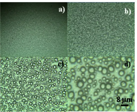
A slow cooling during the solidification of the foil, induces the production of low number of assembled nuclei/volume and big dimension of the beads, as reported in Fig. 1a (opaque PMMA foils) of the order of microns and observed with higher optical magnifications in Fig. 1b,1c and 1d as will be explained in the following.
The control of the cooling is managed using substrates with different thermal conductivity. The key parameters in the production of clear or opaque PMMA foils are based on the cooling rate, temperature gradient, solution properties and adopted chemical solvent.
Fig. 1. Optical images of opaque PMMA at different magnifications
The PMMA effective density was changed using suitable chemical approaches. The density of the solid samples was measured by the weight method consisting of two stages: a Mettler-Toledo balance with ±1 µg absolute accuracy to measure the weight of a well-defined surface area and thickness of the foils. Then, the foil was gripped between two polymeric slices with a contrasted colour obtaining a single block. Afterward, the block was polished and the cross-section of the foil was measured by optical microscope, obtaining a final thickness of 9 µm±2 µm. By the mass-to-area ratio of the foil, an areal density of 1.18 g/cm3 for the clear PMMA and of 0.75 g/cm3 for the opaque PMMA were evaluated. In Fig.1 are reported the optical image of opaque PMMA magnified x5 (Fig. 1a), x10 (Fig. 1b), x40 (Fig. 1c) and x100 (Fig. 1d) times. The average dimension of the beads is 3.5 mm while the average thickness of the cell-wall is 0.8 mm evaluated in an area of 3.8x3.8 µm2.
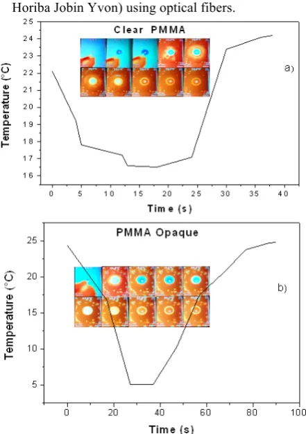
A FLUKE Ti100 CCD thermocamera was employed during the preparation of the clear and opaque PMMA foils for monitoring the temperature gradient. By the thermocamera images, it is possible to observe in both cases an initial temperature of about 24°C. During the preparation of the clear PMMA, using the chemical solution and a metallic holder, the solution temperature reaches a minimum value of 16.5°C. During the preparation of the opaque PMMA, rich in beads, using the chemical solution and a plastic holder, the solution temperature reaches a minimum temperature of 5.1°C. Fig. 2a shows the images obtained by a thermo-camera during the preparation of clear PMMA foil (inset) and a plot of the temperature of the solution as a function of the time. Fig. 2b shows the images obtained by a thermo-camera during the preparation of the opaque PMMA foil (inset) and a plot of the temperature of the solution as a function of the time.
Optical measurements of the prepared polymers were performed using different lamp sources with characteristic light peaks from near UV region, to Vis and to near IR region, and using a high resolving monocromator spectrophotometer system (Lynear-Horiba Jobin Yvon) using optical fibers.
Fig. 2. Images obtained by a thermo-camera during the preparation of clear PMMA foil (a) and during the preparation of opaque PMMA foil (b).
To characterize the composition of the foils the different elements were evaluated by Rutherford Backscattering Spectrometry (RBS) and Elastic Recoil Detection Analysis (ERDA), for hydrogen measure component, using 2.0 MeV He+ ions at Tandetron Lab [11], Nuclear Physics Institute of the ASCR, in the Czech Republic.
Incoming helium ions arrive on the substrate orthogonally then they are backscattered and detected at an angle of 170° by Ultra-Ortec PIPS detector placed below the incoming beam in the Cornell geometry for RBS analysis [12], whereas during ERDA the incoming beam angle is 75° in glancing and the scattering angle is 30° where the forward recoiled atoms (light elements, such as protons) are detected by a Canberra PD-25-12-100 AM detector fixed in plane with the incoming ion beam and covered by a 12 µm Mylar foil to avoid the detection of back-scattered He+ ions [13].
Typically, RBS and ERDA spectra were evaluated and transformed into concentration-depth profiles taking into account all the parameters involved in particles-solid interaction and experimental configuration (stopping power, elastic recoil-cross section, kinematic and geometric factors, energy spreading). Spectra were
studied comparing with simulation data by utilizing SIMNRA 6.06 code [14] and cross-sections data from IBANDL [15]. The typical He+ ion current for each analysis, measured with a suitable Faraday cup, was about 5.3 nA and the irradiation time was about 5 minutes for the clear PMMA and 10 minutes for the opaque PMMA, no more prolonger times were adopted to avoid the thermal degradation of the samples due to ion beam irradiation dose.
Successively, clear PMMA and opaque PMMA, with and without AuNPs, have been irradiated using a Nd:YAG laser, 3 ns of duration, 1064 nm of wavelength, 1010W/cm2 of intensity, delivering an energy of 100 mJ at Messina University. Moreover they were irradiated using an Iodine laser at 1315 nm wavelength, 300 ps pulse duration, 600 J pulse energy and 1016 W/cm2 intensity in PALS facility (Czech Republic).
3. Results
Optical measurements of 8 µm PMMA absorption at 1064 nm and 1315 nm were performed in order to investigate on the effect of near IR irradiation of the prepared polymer to be laser irradiated. The optical measurements were performed using a Nd:YAG laser operating at very low energy, under the ablation threshold. The absorption measurements of the prepared samples at 1064 nm and 1315 nm, the wavelength of the two lasers used in order to produce plasma and accelerated protons, and the absorbance increase using embedded AuNPs is reported in Fig.3.
Fig. 3. Absorbance at 1064 and 1315 nm for PMMA clear, opaque and opaque containing Au NPs 1% wt (b) .
The transmission curve in ref [16] shows two absorption peaks located at 1100 nm and 1300 nm at which transmission is about 70% and 68% having high transparency for the clear PMMA. Fig. 3b reports the absorbance of PMMA clear and opaque at two different wavelengths, and the absorbance value at 1064 nm for PMMA containing Au NPs 1% wt.
1 2
0.3 0.4 0.5 0.6 0.7 0.8 0.9 1.0
Abs
or
banc
e
PMMA species
Cl
ear
O
paque
1064 nm
1315 nm
PMMA +AuNP
RBS and ERDA analyses have been evaluated qualitatively and quantitatively both the elements and the hydrogen concentrations contained into the prepared polymeric foils.
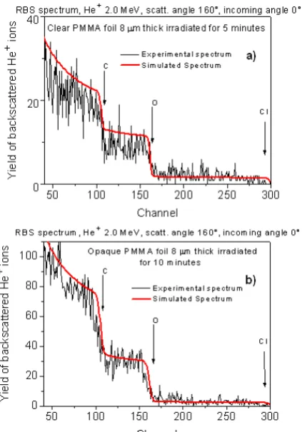
Fig. 4. RBS spectra achieved irradiating clear (a) and opaque (b) PMMA foils.
In Fig. 4a is reported the RBS analysis measurement performed in clear PMMA foil. The maximum atomic concentrations of C, O, and Cl into clear PMMA found at a depth of 400 nm are 60%, 36% and 0.8%, respectively. The spectra show the experimental data and the simulation data (solid red line) comparison from which the quantitative concetration have been evaluated.
In Fig. 4b is reported the RBS analysis measurement performed in opaque PMMA foil. The maximum atomic concentrations of C, O, and Cl into opaque PMMA found at a depth of 400 nm appears to be 70%, 26% and 0.5%, respectively.
Fig. 5. ERDA analysis for the clear and opaque PMMA foils
Thus, in this case an increment of carbon and chlorine and a decrement of the oxygen are measured with respect to the clear polymer.
Fig. 5 reports the comparison between the ERDA analysis in clear and opaque PMMA foils. These results are in agreement with that showed by the thermocamera: the evaporation in the clear PMMA is lower than in the opaque PMMA as well as the oxygen concentration. The hydrogen content in both polymer species is comparable. In Fig. 6 are reported three spectra revealed by SiC detectors, at a flight distance of 74.5 cm from the target, in TOF approach during the laser irradiation of clear PMMA, opaque PMMA and opaque PMMA containing 1% of embedded AuNPs (50 nm size).
Fig. 6.TOF spectra obtained by SiC detector irradiating at low laser intensity clear (a), opaque (b), and opaque PMMA containing gold NPs (c).
200 400 600 800 1000 0
100 200 300 400 500 600
ERDA spectrum, He+ 2.0 MeV, scatt. angle 30°, incoming angle 0°
Hy
drogen
rec
oil
nu
cl
ei (
Coun
ts)
Channel Opaque PMMA 9 µm thick Clear PMMA 9 µm thick
0.0 1.0x10⁻⁶ 2.0x10⁻⁶ 3.0x10⁻⁶
0.0000 0.0005 0.0010 0.0015 0.0020 0.0025 0.0030
PMMA Clear 8 µm EL= 96mJ, Dt = 3 ns Finc=0°
SiC 8 @ -500V 0° forward d = 74.5 cm
Yiel
d (V)
TOF (s) Photopeak
No Ion Acceleration
a)
0.0 1.0x10⁻⁵ 2.0x10⁻⁵ 3.0x10⁻⁵ 0.0000
0.0005 0.0010 0.0015 0.0020 0.0025
0.0030 PMMA Opaque 8 µm
EL= 96mJ, Dt= 3 ns
Finc=0°
SiC 8= -500V 0° forward d = 74.5 cm
Yiel
d (V)
TOF (s) H+=150 eV
Photopeak
b)
0.0 5.0x10⁻⁶ 1.0x10⁻⁵ 1.5x10⁻⁵
0.0000 0.0005 0.0010 0.0015 0.0020 0.0025 0.0030
PMMA Opaco + Au NPs EL= 96mJ, Dt = 3 ns Finc=0°;SiC 8= -500V 0° forward; d = 74.5 cm
Yiel
d (V)
TOF (s) H+=300 eV
0 20 40 60 80 100 120 140 160 180 200 0
1 2 3 4 5
Yie
ld
(V)
TOF (ns)
PALS, PMMA, 8 um EL=500 J, FP = -100 um d(TOF)= 60 cm
SiC detector, forward, 30° Photopeak
E(H+)=600 keV
a)
0 20 40 60 80 100 120 140 160 180 200
20 40 60
Yi
el
d
(V
)
TOF (ns)
PALS, EL=500 J, FP=-100um PMMA+AuNPs, 1%wt, 8 um d(TOF)=60 cm,
SiC detector, forward, 30° Photopeak
b)
E(H+)=1.9 MeV
The used laser was a Nd:YAG operating at 1064 nm wavelength, with 3 ns pulse duration and 1010 W/cm2 intensity.
In the first case the clear PMMA is transparent to the laser wavelength, thus the released laser energy is minimal and no ion acceleration occurs (Fig. 6a). In the second case the opacity of the polymer enhances the laser absorption and more energy is transformed in ion acceleration, detecting maximum proton energy of 150 eV (Fig. 6b). In the third case the presence of the Au NPs permits to increase the laser absorption and to enhance the electron density of the plasma, thus the maximum proton energy reaches 300 eV (Fig. 6c).
The enhancement of 50% of proton energy is due to the increment of the electric field [17].
Similar results were also obtained irradiating the polymer with high intensity laser at PALS at 1016 W/cm2 using 1315 nm wavelength and pulse duration of 300 ps. The acceleration was performed using thin PMMA foils, 8 micron in thickness, in the forward direction in TNSA regime. In these experiments SiC was placed in forward direction at 60 cm distance from the target and laser was focalized on the target with 70 micron spot diameter. X-ray, electrons and ions were produced by the hot and dense plasma and protons were detected at high kinetic energy, as expected.
Fig. 7. TOF spectra obtained by SiC detector irradiating at high laser intensity clear (a) and opaque PMMA containing Au NPs (b).
The laser irradiation of the clear PMMA is lower absorbed and a cold plasma is obtained accelerating a low proton yield at a kinetic energy of 600 keV (Fig. 7a). The laser irradiation of the opaque PMMA in which Au NPs are embedded produces hot plasma and a very good forward acceleration in TNSA regime, accelerating protons up to 1.9 MeV (Fig. 7b). It means that the high intensity laser produces high relativistic electron acceleration at the polymer surface, thanks to the presence of high Au nanoparticle concentration. Such electrons are transmitted to the back face of the thin film producing high positive charge concentration in the polymeric film. Coulomb explosion is generated in the solid and ions are emitted. The high electric field generated in the back face of the target (forward direction) drives the ion (protons, carbon and oxygen) acceleration. The high proton energy is due to the increment of the electric field driving the acceleration which depends on the temperature and the electron density of the produced plasma, according to literature [17].
4. Summary and conclusions
Hydrogenated polymeric targets, such as PMMA, can be prepared as advanced targets to be have low absorption or high absorption in the near IR wavelengths. The study as the aim to use thin PMMA foils to be laser irradiated at high intensity and to produce plasma in which high proton acceleration can occurs.
Particularly the use of porous opaque polymer, containing microstructured beads, or metallic nanoparticles embedded inside it permit to enhance both the laser absorption coefficient, inducing surface plasmon resonance (SPR) effects [6], and the plasma electron density with a significant increment of the resulting ion acceleration energy.
The maximum acceleration in the polymer isobtained using opaque PMMA as a matrix in which Au NPs have been embedded. At relatively low laser intensities, of the order of 1010 W/cm2, the maximum proton acceleration is 300 eV, demonstrating that the PMMA with Au NPs could be a good candidate target to accelerate protons at high yield and energy, useful for many applications.
The use of opaque PMMA containing micrometric beads confers high laser absorption and a good plasma production, but the addiction of Au NPs permits to enhance the electron plasma density and the plasma temperature, i.e. the electric field driving the proton acceleration from TNSA regime.
The research has been realised at the CANAM (Center of Accelerators and Nuclear Analytical Methods) infrastructure LM 2015056 and has been supported by project No. P108/12/G108.
References
1. L. Torrisi, M. Cutroneo, L. Calcagno, M. Rosinski and J. Ullschmied, Journal of Physics: Conference Series 508 012002 (2014).
2. I.G. Jiang, Y.S. Zhou, W. Xiong et al.,Opt. Lett. 39
3034-3037(2014).
3. L. Torrisi, M. Cutroneo, V. Semian, G. Ceccio, Applied Surface Science 351 580-587 (2015). 4. I. Capan, R. Capan, T. Tanrisever, S. Beyaz, Mater.
Lett. 59 2468-2471 (2005).
5. M. Cutroneo, V. Havranek, A. Mackova, V. Semian, L. Torrisi, L. Calcagno, Nuclear Inst. and Methods in Physics Research, B, 371 344-349 (2016). 6. M.A. Garcia, J. Phys. D: Appl. Phys: 44 283001
(2011).
7. L. Torrisi, Molecules 19 17052-17065 (2014). 8. C.B. Simone and R. Rengan, Cancer J. 20(6):427-32
(2014).
9. L. Torrisi, Recent Patents on Nanotechnology
9(1),51-60 (2015).
10. N. Patra, A. C. Barone, M. Salerno, Adv. Polym Technol. 30 1 12-20 (2011).
11. Canam Website 2017:
http://canam.ujf.cas.cz/en/laboratory/lt-laboratory-of-tandetron
12. E. Kotai, AIP Conference Proceedings 392 631 (1997).
13. L. Torrisi and M. Cutroneo, Surface and Interface Analysis 48 (1) 10-16 (2016).
14. M. Mayer, SIMNRA version 6.06,
Max-Planck-Institut fur Plasmaphysik, Garching, Germany,
2011, available at: http://home.rzg.mpg.de/~mam/Download.html
15. IBANDL actual website 2017:
http://www-nds.iaea.org/ibandl/
16. I. Jones and J. Rudlin, Joining Plastics 2006, London, National Physical Laboratory (NPL), 25-26 April 2006
17. L. Torrisi, M. Cutroneo, and J. Ullschmied Physics of Plasmas 24 043112-043123 (2017).
18. L. Torrisi, Recent Patents on Nanotechnology 9(1), 51-60 2015.
19. L. Torrisi, S. Cavallaro, M. Cutroneo, J. Krasa and D. Klir, Phys. Scr. T 161 014026 (2014).