RADIATION PATTERN AND PERFORMANCE
ANALYSIS OF RECTANGULAR MICROSTRIP
FEEDPATCH ANTENNA
Khushbu Ahirwar
1, Sunil Kumar Singh
2, Rajeev Chauhan
3,
Madan Singh
4Mahipal Singh
51,2
Department of Electronics & Communication Engg.,Jabalpur Engg. College, Jabalpur(M.P) India
3
Department of Electronics & Comm. Engg.,St. Aloysius Institute of Technology, Jabalpur(M.P) India
4
Department of Physics and Electronics, National University of Lesotho, Lesotho, Southern Africa
5
Department of Physics, Govt. Post Graduate College, Bageshwar (Uttarakhand) India
ABSTRACT
The technological trend has focus and much effort into the design of a Microstrip patch antenna. In this paper
a design have been considered, results of this design have been compared with each other by using IE3D an
electromagnetic simulation package by Zeland Software Inc. presently by Mentor Graphics Inc. and design
parameters are calculated using MATLAB software. We have compared the results of the design in the
frequency band 2GHz to 3.5GHz and the best configuration of antenna with suitable Return Loss(RL),VSWR,
Bandwidth, Gain, 2D and 3D Radiation Pattern has been suggested that can be used in practice for
communication purpose especially for mobile communication.
Keywords:
Microstrip patch antenna, Transmission line model, IE3D Electromagnetic SimulationPackage, MATLAB.
I INTRODUCTION
The purpose of this work is to design a microstrip patch antenna using commercial simulationsoftware like
IE3D[1]. The IE3D previously by Zeland Software Inc. Presently by Mentor Graphics Inc. has been recently
considered as the benchmark for electromagnetic simulation packages. It is a full wave, method of moment
(MOM) simulates or solving the distribution on 3D and multilayered structures of general shape. The primary
formulation of the IE3D is an integral equation obtained through the use of Green’s functions. In the IE3D, it is
possible to model both the electric current on a metallic structure and a magnetic current representing the field
field on the surface of the conductor is considered as zero. Though the patch is actually open circuited at the
edges, due to the small thickness of the substrate compared to the wave length at the operating frequency, the
fringing fields will appear at the edges. Here, the "Transmission Line Model" [2-4] has been used to predict the
radiation characteristics of the patch. In this model, the patch antenna is treated as two parallel radiating slot
sanda transmission line inter connecting them (Figure2). The electric and magnetic fields are calculated
separately for each slot and the resultant field pattern is a combination of the two slots. The E-plane radiation
pattern of the patch given by this model is expressed as follows [2]-
(1)
(2)
(3) The radiated power is expressed as follows-
(4)
Where
The radiation resistance is defined as follows-
(5)
Fig. 2: Transmission line Model of Microstrip Patch Antenna
III DESIGN PROCEDURE
A microstrip antenna can be designed using either the transmission line model or the cavity model (more
complex models also exist that suit a particular design). We have used the transmission line model since it is
fairly simple to implement and results in antenna designs with reasonably good performance in terms of return
loss and efficiency. It is also quite well suited to the rectangular designs that we have considered (other popular
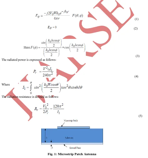
designs include circular, elliptical and disc like). The design starts with selecting the operating frequency fr,
selecting a substrate with the required permittivity εr and de fi ni ng the wi d t h o f t he s ub s tr at e s
(Figure1). Thick substrates with low permittivity result in antenna designs with high efficiency and large band
widths. Thin substrates with high permittivity lead to a smaller antenna size but with a lower band width and a
high radiation loss[5]. The tradeoffs between substrate thickness and permittivity and antenna band width and
efficiency have been discussed in [2].According to the transmission line model, the length L and width W of
the patch are calculated as[6]-
Where vo is the speed of light in free space, εreff is th eeffective permittivity and 2ΔL is the extension in length
due to fringing effects-
Although the design of the patch is quite simple, the design of the feeding mechanism is not that straight
forward. There are four possible methods that can be used- Microstrip-linefeed, Probefeed, Aperture-coupled
The designed patch antenna is then simulated in IE3D, which is EM software which is extensively used for the
Design and the Simulation of the Patch Antenna at a frequency of 2.65 GHz.The structures of the designed
antenna are shown below in the figures with the Microstrip feed line.
Fig.3 Fig.4
Fig.3: Rectangular Patch Antenna with Microstrip feed & portas signed for excitation
Fig.4: A meshed Rectangular Patch Antenna
Fig.5: 3D Structure of the meshed Rectangular Patch Antenna with Simple Microstrip Feed
Line
V RESULTS OF THE DESIGN
Fig.7: VSWR Vs Frequency
Fig.9: Smith Chart ofthe design
Fig.10: 2D Radiation Pattern at 2 GHz Fig. 11: 3D radiation Pattern at 2GHz
Fig.14: Radiation pattern 2D at 3.5 GHz Fig.15: 3D radiation Pattern at 3.5 GHz
VI CONCLUSION
The aim of this paper is to design a best and optimum Rectangular Patch Microstrip antenna in the frequency
range1GHz to 3GHz which can be useful for the communication purpose. It is good to see that the return loss
has a negative value which states that the losses are minimum during the transmission. In this design the RL is
measured- 14 Db at resonating frequency 2.65 GHz.The VSWR for the design in between1to2 as we can say the
level of mismatch is not so high. For this design it is measured and can be appreciated as the most desired 1.02
at the resonating frequency 2.65GHz. When the antenna efficiency is measured has the most desired efficiency
of 80.1% at 2.65 GHz.
Table 1: Design Parameters -Input parameters [7-14]
Design Parametres Values
εr 2.4 (RT-Duroid)
vo 3x10⁸ m/sec
fr 2.65 GHz
h 1.58 mm
tanδd 0.001
W 39.6 mm
L 47.9 mm
Z0 50 Ω
Wc 4.2 mm
Y0 13 mm
Polarization Linear
analyzed, indicating that now a stage of energy during the transmission. We can say that the energyloss is very
minimum with the RL values of-14 dB for the design. By comparing all the responses and the patterns of the
design it can be said as the it is optimized design with resonating frequency, suitable bandwidth, higher gain and
antenna efficiencyof 80.1%. A Microstrip Line feed Rectangular Patch Antenna with the dimension parameters
h-1.58mm (substrate thickness), L- 47.9 mm (length of the patch), W- 39.6 mm (width of the patch) with a
dielectric constant of 2.4 at an operating frequency of 2.65GHz can be said the best and optimized design and
can be used in practice for the communication purpose.
REFERENCES
[1]
Nader Behald, Simulationofa2.4GHz Patch Antenna Using IE3D a Tutorial, EEL, Spring, 2007
[2] Ramesh Garg, Prakash Bartia, InderBahl, Apisak Ittipiboon, Microstrip Antenna Design Handbook, Artech
House Inc. Norwood, MA 253‐316, 2001,pp1‐68
[3] Pozar, D.M.and D.H.Schaubert (Eds), The Analysis and Design of Microstrip Antenna sand Arrays ,IEEE
Press, NewYork,1996
[4] Yasir Ahmed, Yang Hao and Clive Parini, A31.5 GHz Patch Antenna Design for Medical Implants,
University of London, International Journal of Antennas & Propagation, 2008, 2008
[5] D.M. Pozar, Microwave Engineering, Second Edition, John Wiley and sons, Inc.1998
[6] Wentworth, M.Stuart, Fundamentals of Electromagnetics with Engineering Applications, John Wiley &
Sons, NJ, USA, 2005, pp 442‐445
[7] Alla I.Abunjaileh, Ian C. Hunter and Andrew H. Kemp, Multi‐Band Matching Technique for Microstrip
Patch Antenna Receivers,School of electronic and electrical engineering, The University of Leeds, IEEE ,
EUMC. 4405174, 2007
[8] S.Satthamsakul, N. Anantrasirichai, C. Benjangkapraset and T. Wakabayashi, Rectangular Patch Antenna
with insetfeed and modifier Vol4,2001
[9] Richard C. Johnson and Henry Jasik, Antenna Engineering Handbook Second Edition, Mc Graw Hill, Inc.
NY, USA 1984, pp7‐1to 7‐14
[10] D.M. Pozar, Microstrip Antennas, Proc .IEEE,Vol.80,1992, pp 79‐91
[11] D.M. Pozar and D. H. Schaubert(Eds), Analysis and Design of Microstrip Antennas and Array, IEEE
Press,NewYork,1996
[12] Y. T. Lo and S. W. Lee, editors, Antenna Hand book Theory, Applications & Design, Van Nostrand Rein
Company, NY, 1988
[13] M. Olyphant, Jr. and T. E. Nowicki, Microwave substrates support MIC technology, Microwaves, Part I,
Vol.19, No.12, 1980, pp74‐80
[14] A. Derneryd, A theoretical investigation of the rectangular microstrip antenna element, IEEE Transactions

![Table 1: Design Parameters -Input parameters [7-14]](https://thumb-us.123doks.com/thumbv2/123dok_us/7750361.1270483/6.595.75.522.77.755/table-design-parameters-input-parameters.webp)
