Applications of ECH on the DIII-D tokamak and projections
for future ECH upgrades
R. Prater1, R.J. Buttery1, J. DeBoo1, J.R. Ferron1, A. Garofalo1, C.T. Holcomb2, G.L. Jackson1, R.J. La Haye1, J.M. Lohr1, T.C. Luce1, C.C. Petty1, P.A. Politzer1, W.M. Solomon3 and F. Turco4 1General Atomics, P.O. Box 85608, San Diego, California 92186-5608, USA
2Lawrence Livermore National Laboratory, Livermore, California 94550, USA
3Princeton Plasma Physics Laboratory, Princeton, New Jersey 08540, USA 4Columbia University, New York, New York 10027, USA
Abstract.Electron Cyclotron Heating and Current Drive plays an important role in the DIII-D program. In high performance discharges EC power contributes greatly to MHD stability, and this is particularly important for discharges with low rotational torque applied, as will be the case for ITER. Off-axis EC current drive also plays a key role in the actualization of steady-state scenarios by supporting the desired current profile. In order to carry out these applications at higher beta and higher field, an upgrade of the EC power to 15 MW is needed, and the best gyrotron frequency for the DIII-D program is 117.5 GHz.
1 Introduction
The role of Electron Cyclotron Heating (ECH) and Electron Cyclotron Current Drive (ECCD) in DIII-D stems from its unique and useful attributes [1], which differ substantially from the other heating methods available, primarily neutral beam injection (NBI). Unlike NBI, ECH interacts primarily with electrons, it injects no torque or particles, and its heating location in the plasma can be robustly controlled. ECCD can be driven or not, at the user’s discretion, and profiles of heating and current drive can be made narrow or broad. Some applications of the existing 110 GHz ECH/ECCD system on DIII-D to development and exploitation of scenarios are described.
2 Applications of ECH/ECCD to scenarios in DIII-D
The DIII-D program is directed in significant part to support successful operation of ITER and other future devices. One aspect of this support is carried out by generating projected scenarios for ITER in DIII-D and testing the experimental results against integrated models used to project performance, in order to improve those models. ITER differs from most present-day tokamaks in that it is expected to have relatively low applied torque compared to its high moment of inertia, and hence low toroidal rotation speeds. It will also have electron temperature equal to or larger than the ion temperature due to the plasma heating by energetic fusion products, unlike most tokamaks now that are heated by NBI. With low torque and Te=Ti, it is anticipated that plasma performance at ITER-relevant C
Owned by the authors, published by EDP Sciences, 2012
normalized beta (N) will be different from that in more usual high torque high ion temperature discharges, and exploration of these conditions in DIII-D is underway.
The 6 MW ECH system supplements the 20 MW NBI heating system on DIII-D. The NBI system comprises four beamlines, each of which has two independent beam sources that supply 2.5 MW each of neutral deuterium beams when operated at 80 kV. These beamlines were originally oriented to inject with a toroidal component in the co-current direction, but in 2006 one beamline was reversed in toroidal direction, so that it can provide injection in the opposite direction to the other beams. This modification allows operation at high NBI power but with substantially reduced toroidal torque. At total NBI power up to 10 MW the NBI heating can be done with little net torque injected, and higher power can be applied with highly reduced torque. Scaling indicates that application of about 1 Nm of torque in DIII-D corresponds to the anticipated 30 Nm of torque in ITER.
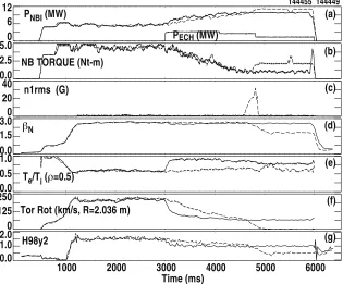
One scenario being developed for ITER is the advanced inductive (AI) discharge, in which a small relatively benign m=3/n=2 neoclassical tearing mode (NTM) arises spontaneously, and ECCD is used to control the m=2/n=1 mode. The effect of the 3/2 NTM is to broaden the current profile, creating weak central magnetic shear and avoiding sawteeth by keeping the safety factor q above 1, while not much affecting confinement. In high torque discharges this approach works well [2], but as the applied torque is reduced toward 1 Nm in discharges with moderately high N (above 2), a large m=2/n=1 tearing mode typically arises, reaching an amplitude of 30 G at the plasma edge which results in prompt toroidal locking of the plasma, with a consequent large loss of confinement and a propensity toward disruption. This behavior is shown in Figure 1, which shows two low torque advanced inductive discharges, one without ECH and one with ECH directed to drive current at =0.45 near the q=2 surface.
The discharge of Figure 1 starts as a conventional high torque AI configuration, but at 3000 ms the beam program ramps down the 5 MW of co-injection, Figure 1(a), and substitutes counter-injection in order to ramp down the torque, Figure 1(b). The total power throughout is in feedback mode to keep N constant at 2.8. Also at 3000 msec, 3.2 MW of EC heating and current drive is added at =0.45. The immediate effect of the EC power is to raise the electron temperature Te, the profiles of which are shown in Figure 2, but it also lowers the plasma toroidal rotation speed by 60%, Figure 1(f), and the ion temperature Ti. The ratio Te/Ti at the plasma mid-radius, shown in Figure 1(e), increases strongly and promptly, at the application of the EC power. The confinement, characterized by the H98y(2) parameter, decreases from 1.5 before the addition of EC power to a still acceptable 1.0 after, shown in Figure 1(g).
Figure 1 shows that adding substantial EC power does not decrease the NBI power needed to maintain constant plasma pressure. Raising Te/Ti , as in Figure 2(a), may be detrimental to confinement, but without the EC power the discharge develops a large, rapidly growing 2/1 NTM, shown in Figure 1(c). This causes the plasma rotation to drop rapidly to zero, as shown in Figure 1(f), as the mode locks, and confinement is strongly degraded to H98y(2)=0.5. But when ECCD is used the low-torque high N condition is maintained to the end of the discharge. For this reason ECCD is usually applied in experiments on AI discharges.
0 6 12 (a) (b) (c) (d) (e) (f) (g) PNBI (MW)
144455 144449
PECH (MW)
0.0 2.5 5.0
NB TORQUE (Nt-m)
n1rms (G)
βN
Te/Ti (ρ=0.5)
1000 2000 3000
Time (ms)
4000 5000 6000
0.0 1.0 0 125 2500.0 0.0 1.5 3.00 20 40 0.5 1.0 2.0 H98y2
Tor Rot (km/s, R=2.036 m)
Fig. 1. A deuterium AI discharge in DIIID with plasma current 1.05 MA, toroidal field -1.65 T, and plasma density 4.2x10¹⁹ m-3. (a) Neutral beam and ECH power; (b) injected neutral beam torque; (c) n=1 mode amplitude; (d) bN from the equilibrium reconstruction; (e) Te/Ti at the mid-minor-radius; (f) plasma rotation at the outer mid-radius; (g) confinement factor H98y(2).
1.2
Te /Ti 0.8
0.4 0.0 1.0 0.8 0.6 0.4 0.2 0.0 0 1 2 3 4 5 0 40 80 q=2
j (A/cm2) Ti (keV)
Te (keV)
Fig. 2. For the discharge of Figure 1, (a) the radial profile of the ratio Te/Ti, and (b) the profiles of the temperatures Te and Ti. The solid lines are at 2805 msec, before the EC power is applied, and the dashed lines are at 3605 ms, with high power EC.
discharges is very different. The hypothesis is that for low torque discharges the main effect of the EC power is to improve stability by affecting the classical stability parameter ’.
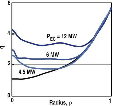
In addition to improving the MHD stability in high performance discharges, ECCD plays a major role in developing and maintaining the current profiles needed for steady state operation scenarios. This line of research is of interest for advanced steady-state scenarios in ITER but is essential for follow-on devices like a demonstration power reactor. DEMO must operate in steady-state, so full noninductive current drive is required, and in order to be economical this requires that the bootstrap fraction be large [4]. Work on DIII-D [5] has shown that discharges with the fraction of noninductive plasma current near unity require significant externally driven current in the region inside the H-mode pedestal. In DIII-D this off-axis current can be driven by a combination of neutral beam injectors that can be tilted vertically and ECCD. Calculations shown in Figure 3 using the GLF23 transport model show that steady-state operation with weak shear and q greater than 2 can be obtained in DIII-D with 9 MW of EC source power and greater than 3 with 15 MW, when combined with off-axis NBI and central electron heating by fast waves. These fully noninductive discharges are predicted to have reactor-relevant ratio Te/Ti > 1 at high N=3.7. Validation of these calculations is a major objective of the DIII-D program.
Radius, ρ
0 2 4 6
0
4.5 MW
6 MW
PEC = 12 MW
1
q
Fig. 3. Calculated profile of the safety factor q for a steady-state DIII-D discharge with
on-axis neutral beams only (bottom curve), with 5 MW of off-on-axis beams plus 4.5 MW, 6 MW, and 12 MW of off-axis ECCD. The toroidal field is 1.75 T.
3 Proposed ECH upgrade for DIII-D
In order to fully explore in DIII-D the regime of high beta steady-state operation with Te/Ti > 1 and low torque, while controlling tearing modes at one or more surfaces, modelling shows that the power of the ECH system will need to be upgraded to 15 MW. This can be done most cost-effectively by adding two 1.5 MW gyrotrons and upgrading the aging 1 MW gyrotrons in the DIII-D system with gyrotrons rated at 1.5 MW. Advances in collector geometry and materials, coupled with use of a depressed collector to reduce the power incident on the collector surface, make higher power gyrotrons more practical. In addition, improved beam tunnel design and materials increase the efficiency, and advanced designs of the mode converter reduce the stray power inside the tube while improving the coupling efficiency to waveguide.
significant effect on the cost. A study was undertaken to determine the optimum frequency for use on DIII-D. The optimization of the gyrotron frequency took into account a number of aspects:
• Operation of the high beta scenarios at toroidal fields near the maximum possible on DIII-D, 2.16 T, is desirable. The normalized performance might be high at lower field, but the absolute performance increases with toroidal field if dimensionless parameters are held fixed.
• The efficiency of ECCD is highest when the wave-particle interaction takes place on the high field side of a flux surface, so that electron trapping is minimized.
• It is desirable to have a range of minor radius where the heating and current drive take place, for a range of toroidal field of interest.
• Excessive 3rd harmonic absorption should be avoided.
• The maximum density accessible to EC waves is proportional to the square of the frequency. Higher density operation is frequently valuable.
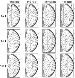
These issues affect a wide range of experiment objectives for ECH/ECCD, so the motivation is to do as well as possible for the highest priority experiments—off-axis current drive and MHD stability improvement—without unduly jeopardizing the important but lower priority experiments. A true optimization can be done only for very narrowly defined objectives; instead, a range of effective operation is needed. Many of the tradeoffs can be immediately recognized from the matrix of toroidal fields and gyrotron frequencies shown in Figure 4. At 2.16 T, 110 GHz is a poor choice because the interaction with the resonance is unavoidably on the low field side, with concomitant loss of current drive efficiency. On the other hand, 120 GHz is a poor choice at 1.7 T because up-shifted third harmonic absorption at the edge will be quite significant. Also, the smallest minor radius where heating can be done is =0.6, which is too far out for many purposes.
1.7 T
110 GHz
2 3 2 3 2 3 2 3
115 GHz 117.5 GHz 120 GHz
1.9 T
2.16 T
Fig. 4. DIII-D equilibria with toroidal field 1.7, 1.9, and 2.17 T (rows) and for gyrotron
frequencies of 110, 115, 117.5, and 120 GHz. The vertical lines are the 2nd and 3rd harmonic
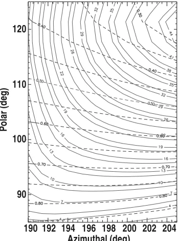
An acceptable accommodation to the conditions listed above is to use 117.5 GHz gyrotrons. Figure 5 shows contours of the minor radius and the driven current as a function of the two steering angles. Current drive from =0.3 to 0.8 is possible, with 25 kA/MW at r=0.5 for the conditions of
this calculation. A design of the 117.5 GHz 1.5 MW gyrotron has been completed at CPI. The proposed plan to upgrade the ECH system is described in detail in [6].
190 90 100 110
Po
la
r (
d
eg
)
120
192 194 196 Azimuthal (deg)
198 200 202 204
Fig. 5. Contours of the r location of maximum heating (dashed lines) and contours of the magnitude of the total driven current (kA/MW), as a function of the vertical steering angle (polar angle) and toroidal steering angle (azimuthal angle). The applied frequency is 117.5 GHz, the toroidal field is -1.9 T, the central density is 5.5x10¹⁹ m-3 and the central electron temperature is 7.3 keV.
Acknowledgment
This work was supported by the US Department of Energy under DE-FC02-04ER54698, DE-AC02-09CH11466, and DE-FG02-04ER54761.
References
1. R. Prater, Phys. Plasmas 11, 2349 (2004)
2. M.R. Wade, et al., Fusion Sci. Tech. 48, 1199 (2005) 3. R. Prater, et al., Nucl. Fusion 47, 371 (2007)