Implementation of Islanding Detection Using Phase-Locked
Loops in Three-Phase Electrical Grid-Interface Power Convertors
Mahesh Thati
& Mahesh Jonnala
1Assistant Professor, Dept of EEE, Institute of Aeronautical Engineering college, Dundigal, Hyderabad.
E-mail:[email protected]
2Masters in Power Electronic Systems from Osmania University, Hyderabad.
E-mail:[email protected]
ABSTRACT:In order to encounter the necessities for gridinterconnection, it is essential that the control of DistributedPower Generation systems (DPGSs) should be improved.Therefore, grid synchronization algorithms play a vital rolefor Distributed Power Generation
Systems (DPGSs).Phase locked loop and
synchronization techniques are one of the most important issues for operating grid-interfaced converters inpractical applications, which involve Distributed Power Generation Systems, Flexible AC Transmission Systems (FACTS), and High Voltage DirectCurrent (HVDC) Transmission, and so on.This paper proposes a systematic PLL modeling anddesign approach to evaluate different frequency-based islandingdetection
methods. Two different types of PLL-based
islandingdetection solution are discussed, accounting for a majority ofthe existing methods. The first method is to modify the PLL toconstantly move the stable equilibrium point. The second methodis to modify the PLL small-signal characteristics to achieve amonotonic instability behavior under the islanded conditions.The design procedures of these methods are presented using theproposed PLL modeling approach.
KEYWORDS-Converter stability, distributed generation (DG),islanding detection, phase-locked loop (PLL).
I. INTRODUCTION
Renewable energy resources are being widely used now
adays for power generation. Three phase
inverterimplemented in the unified control strategy is effective andgives the better inductor current [1]. Distributed generation(DG) is emerging as a viable alternative when renewable ornonconventional energy resources are available, such as windturbines, photovoltaic arrays, fuel cells, micro turbines [2], [4].
Most of these resources are connected to the utility throughpower electronic interfacing converters, i.e., three-phaseinverter. Moreover, DG is a suitable form to offer high reliableelectrical power supply, as it is able to operate either in thegrid-tied mode or in the islanded
mode [3]. In the grid-tiedoperation, DG deliveries power to the utility and the localcritical load. Upon the occurrence of utility outage, theislanding is formed. Under this circumstance, the DG must betripped and cease to energize the portion of utility as soon aspossible according to IEEE Standard 929-2000 [5]. However,in order to improve the power reliability of some local criticalload, the DG should disconnect to the utility and continue tofeed the local criticalload [6]. The load voltage is key issue of these two operationmodes, because it is fixed by the utility in the grid-tiedoperation, and formed by the DG in the islanded mode,respectively. Therefore, upon the happening of lonely i.e.,islanding, DG must take over the load voltage as soon aspossible, in order to reduce the transient in the load voltage.And this issue brings a challenge for the operation of DG.Droop-based control is used widely for the power sharing ofparallel inverters [12], [13], which is called as voltage modecontrol in this paper, and it can also be applied to DG torealize the power sharing between DG and utility in the gridtied mode [14]. In this situation, the inverter is alwaysregulated as a voltage source by the voltage loop, and thequality of the load voltage can be guaranteed during thetransition of operation modes. However, the limitation of thisapproach is that the dynamic performance is poor, because thebandwidth of the external power loop, realizing droop control,is much lower than the voltage loop. Moreover, the gridcurrent is not controlled directly, and the issue of the inrushgrid current during the transition from the islanded mode tothe grid-tied mode always exists, even though phase lockedloop (PLL) and the virtual inductance are adopted. In thehybrid voltage and current mode control, there is a need toswitch the controller when the operation mode of DG ischanged. During the interval from the occurrence of utilityoutage and switching the controller to voltage mode, the loadvoltage is neither fixed by the utility, nor regulated by the DG,and the length of the time interval is determined by theislanding detection process.
microgrids that operatewith multiple distributed generators (DGs) and loadscannot be controlled by a traditional synchronizer. It isnecessary to control multiple distributed generators andenergy storage systems in a coordinated way for themicrogrid synchronization. Power converter system can beoperated in islanded or standalone mode. In idealcondition, the output voltage parameters like amplitude,frequency and phase cannot be controlled for a gridtogether where multiple DGs are working in parallel;whereas the same parameters for standalone inverter to beconnected to grid can be controlled by means of the variouscontrol strategies [1].
General structure of distributed powersystem [1]
Therefore, the main issue in thisapproach is that it makes the quality of the load voltageheavily reliant on the speed and accuracy of the islandingdetection method [7]-[11].Therefore, it is necessaryand also our intention to investigate the inherent mechanismand the converter output frequency dynamic behaviors usinga systematic approach, which can be eventually applied tomultiple-inverter conditions.This paper is dedicated to the modeling and design procedures for frequency-based islanding detection.
The Inverter which working in standalone modeand is ready for synchronization to go for grid connectedmode, has to closely track the grid frequency [2]. Normallygrid frequency is varying according to load variations [3].Any mismatch on frequency may lead to generateunwanted circulating currents and may lead to damageelectronic devices. In this regard use of PLL is widelypreferred technique that enables tracking the grid frequency[4].Various techniques of synchronization of theinverter based on the Phase Locked Loop (PLL)
aredescribed in the second section named
Methodology.Different issues and solutions related to different PLLmethods are also described in it.
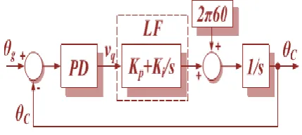
Fig. 1. Synchronous reference frame PLL linear model.
Fig. 2.Typical PLL linear model.
Two typesof PLL-based islanding detection methods will be discussedand compared with the typical PLL. Figs. 1 and 2 show thetypical SRF PLL structure and its linear model. The closedloop response is shown in (1), where the phase-detectorgainkPD equals the input ac voltage amplitude Vg.
II. ISLANDING DETECTION BASED ON
PLLLARGE-SIGNAL STABILITY
Fig. 3.Three-phase grid-interface power converter system.
The nonlinear PLL modelunder the islanded condition is shown in Fig. 4. Under theislanded condition, the PLL still tracks the inverter terminalvoltage produced by the inverter’s current flowing to ZL.Therefore, there is a self-synchronization loop shown in themodel.
Fig. 4.SRF PLL model under the islanded condition.
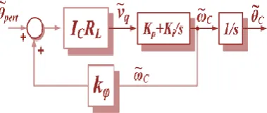
This nonlinear PLL model can be linearized around the linefrequency to obtain the small-signal model [5], as shown in Fig. 5. IcRL is considered as kPD.
Fig.5. Linearized small-signal PLL model under islanded condition.
If the equilibrium point changes, the PLL output will automatically react to this change. Therefore, many islanding-detectionmethods are proposed to actively perturb the equilibrium point.Fig. 6 shows an example of PLL-based islanding detectionusing such a way.An additional large-signal feedback loop is introduced andmultiplied by a gain kpt (a 0.5 or 1 Hz small triangular signalbetween 0 and kmax). This additional
feedback loop constantlyshifts the equivalent resonant frequency. Thus, the PLL outputfrequency will keep moving all the time.As shown in Fig. 7, the output frequency will follow theinput injection signal kpt. Eventually, the average value ωavofthe PLL output will stay lower than 60 Hz to ensure F = 0.
Fig. 6.Modified PLL with a large-signal feedback for islanding detection.
According to Fig. 7, the PLL output ωC can be directlymonitored to detect the islanding condition, and a low-passfilter (LFP) is used to eliminate the high-frequency noise.The islanding-detection protection signal is set when ωC islower than the ωth or the variation range of ωC is beyond thethreshold.The only design parameter is kpt, because it is a very lowfrequency signal, much lower than the PLL bandwidth. Theoutput of the PLL can be assumed to be at the steady state allthe time.
Fig. 7. First PLL output behavior when the islanding condition occurs.
as shownin Fig. 9.
Fig. 9.Modified PLL model under the stiff grid-connected condition.
III. ISLANDING DETECTION BASED ON
PLLSMALL-SIGNAL STABILITY
The PLL cannot detect the paralleled RLC load, becausethe PLL is stable according to (5). Therefore, the equilibriumpoint itself can be modified to be unstable. With this idea, thePLL can be modified as shown in Fig. 15. An additional smallsignal feedback term is introduced with a constant gain N.Then, the equivalent small-signal PLL model aroundthe equilibrium point at the islanded condition is shown
in Fig. 16
Fig. 15. Modified PLL with a small-signal feedback for islanding detection.
Fig. 16. Small-signal model of the modified PLL for islanding detection.
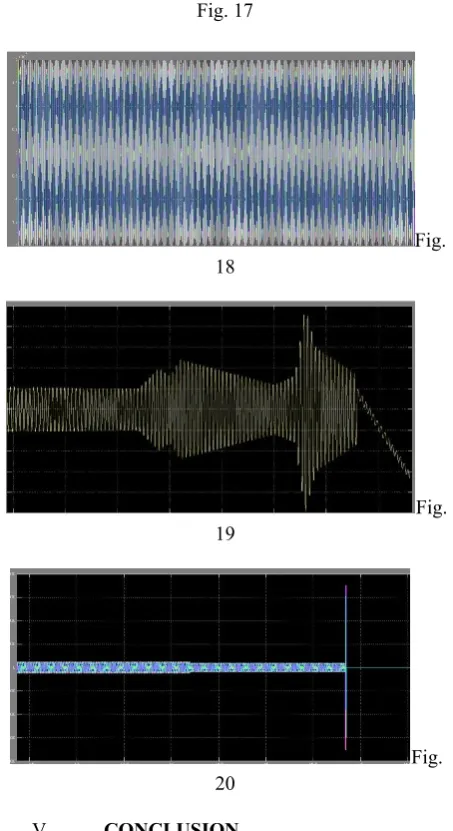
IV. SIMULATION RESULTS
The PLL behavior is verified in a 2.5 kW two-level three-phase PWM converter system shown below
Fig. 17
Fig. 18
Fig. 19
Fig. 20
V. CONCLUSION
bandwidth, thereby requiring a low-frequency, for example, 1 Hz, signal injection. For the small-signal instabilitybased method, the proposed small-signal PLL model showsthat the additional small-signal loop gain design is determined by the local load power quality factor and its resonantfrequency to ensure islanding-detection performance.
.REFERENCES
[1] “Renewables 2007 Global Status Report,”
Paris:REN21Secretariatand Washington, DC:
Worldwatch Institute, REN21. 2008.
[2] IEEE Standard for Interconnecting Distributed Resources withElectric Power System, IEEE standard 1547, 2003
[3] L. Kumpulainen, K. Kauhaniemi, P. Verho, and O. Vähämämäki,“New Requirements for System Protection Caused by DistributedGeneration,” 18th International Conference on Electricity Distribution,Turin, Jun. 2005.
[4] J. M. Lee, “Islanding detection methods for microgrids,” M.S. thesis,Dept. Elect. Comput. Eng., Univ. Wisconsin-Madison, Madison, WI,USA, 2011.
[5] D. Dong, “Ac-dc bus-interface bi-directional converters in renewableenergy systems,” Ph.D.
dissertation, Dept. Elect. Comput. Eng.,
VirginiaPolytechn. Inst. State Univ., Blacksburg, VA, USA, 2012.
[6] T. N. Thacker, “Phase-locked loops, islanding detection and microgrid operation of single-phase converter systems,” Ph.D. dissertation,Dept. Elect. Comput. Eng., Virginia Polytechn. Inst. State Univ.,Blacksburg, VA, USA, 2009.
[7] Z. Ye, A. Kolwalkar, Y. Zhang, P. Du, and R. Walling, “Evaluationof anti-islanding schemes based on nondetection zone concept,” IEEETrans. Power Electron., vol. 19, no. 5, pp. 1171–1176, Sep. 2004.
[8] Z. Ye, R. Walling, L. Garces, R. Zhou, L. Li, and T. Wang, “Studyand development of anti-islanding control for grid-connected inverters,” Dept. Energy, Nat. Renew. Energy Lab., Golden, CO, USA,Tech. Rep. NREL/SR-560–36243.
[9] T. Thacker, F. Wang, R. Burgos, and D. Boroyevich, “Implementationof control and detection algorithms for utility interfaced power conversion systems,” in Proc.
IEEE Appl. Power Electron. Conf. Exposit.,Mar. 2006, pp. 1745–1750.
[10] Y. Jung, J. Chio, B. Yu, J. So, and G. Yu, “A novel active frequencydrift method of islanding prevention for the grid-connected photovoltaicinverter,” in Proc. IEEE Power Electron. Specialists Conf., Jun. 2005,pp. 1915– 1921.
[11] M. Moeneclaey. The optimum closed-loop transfer function of aphase-locked loop used for synchronization purposes. IEEE Trans.Communications. Vol.31, No.4, pp.549-553, 1983.
[12] M. T. Hill, “A frequency steered phase-locked loop”. IEEE Trans.Communications. Vol. 45, No.6, pp. 737-743, 1997.
[13] Nikos Margaris, Vassilios Petridis, D. Efthymiatos. “Phase- lockedloop control of a nonlinear DC motor”. IEEE Trans.IndustrialElectronics, Vol. 29, No.1, pp 91-93, 1982.
[14] Ching-Tsai Pan, Emily Fang, “A phase-locked- loop-assistedinternal model adjustable speed controller for BLDC motors”. IEEETrans. Industrial Electronics, Vol. 55, No.9, pp 3415- 3425, 2008.
[15] Mu-Ping Chen, Jan-Ku Chen, Katsuaki Murata, et al. “Surgeanalysis of induction heating power supply with PLL”. IEEE Trans.Power Electronics, Vol. 16, No.5, pp. 702-709, 2001.
[16] Hidekazu Miura, Shinsuke Arai, Fumihiro Sato, et al. “Asynchronous rectification using a digital PLL technique forcontactless power supplies”. IEEE Trans. Magnetics, Vol. 41, (10),pp. 3997-3999. 2005.
[17] M. K. Ghartemani, M. R. Iravani. “A nonlinear adaptive filter foronline signal analysis in power systems applications” IEEE Trans.Power Delivery, 2002, Vol. 17, No.2, pp. 617-622, 2002.
[18] MasoudKarimi-Ghartemani and M. Reza
Iravani,”Robust andFrequency-Adaptive Measurement of Peak Value”IEEE transactionson power delivery, vol. 19, no. 2,pp. 481-489, april 2004.
[20] M. K. Ghartemani, M. R. Iravani. “A method for synchronization ofpower electronic converters in polluted and variable frequencyenvironments” IEEE Trans. Power Systems, Vol. 19, No.3, pp.1263-1270, 2004.
BIODATA
Mahesh Thati, a teaching experience of 6 years i.e. from 2012 to 2017 and currently Working as Assistant Professor in Institute of Aeronautical Engineering college, Dundigal, Hyderabad.