274 | P a g e
DIRECT TORQUE AND FIELD ORIENTED CONTROL
OF PMSM USING SVPWM TECHNIQUE
Gangadhar Chandaka
1, G Prasanth
2,
1PG Student [P.E & D],
2Assistant Professor, Department .of EEE,
Avanthi's Research &Tech Academy, VSKP (India)
ABSTRACT
In recent years, variable speed drives using synchronous motors operating from static frequency converter have
become very versatile and a real competitor to both DC and IM drives, especially in high power, low speed range.
Unlike the IM, the synchronous motor can be operated at variable power factor (leading, lagging or unity) as
desired. So, there is an increasing use of synchronous motors as adjustable speed drives. Different types of control
schemes have been suggested for variable speed AC drives fed from static power sources. Static power sources are
now available with DC link inverters of voltage source (VSI) or current source (CSI) type and cyclo converters. The
use of pulse width modulation (PWM) technique in case of VSI drives allows efficient and smooth operation, free
from torque pulsations and cogging, lower volume and weight and provides a higher frequency range compared to
CSI drives. Even for voltage source inverter, the commutation circuit is not needed, if the self-extinguishing
switching devices are used. This project initially discusses the problems associated with different motors and why
we are adapting the permanent magnet synchronous motor (PMSM). It presents the PMSM mathematical model
based on the rotor reference frame. Later, it discusses about the control strategies which are used for controlling the
PMSM. They are scalar control and vector control considering the consistency of selecting the optimal control of
PMSM we go for Field Oriented Control and Direct Torque Control which are of vector type. In this work, we found
the PWM technique which is suitable for generating pulse to the Voltage Source Inverter such that maximum
voltage is utilized. The total work mainly concentrates on optimum control of PMSM with maximum voltage
utilization with less switching losses. Key words: Permanent magnet synchronous motor, Mathematical modeling,
Field
Keywords: Oriented Control, Direct Torque Control, Pulse Width Modulation, Voltage Source
Inverter.
I INTRODUCTION
Electrical ac machines have been playing an important role in industry progress during the last few decades. All
275 | P a g e
conveyor belts, robot arms, cranes, steel process lines, paper mills, waste water treatment and so on. With the
advances in power semiconductor devices, converter topologies, microprocessors, application specific ICs (ASIC)
and computer-aided design techniques since 1980s, ac drives are currently making tremendous impact in the area of
variable speed motor control systems. Nowadays, as in every area of the technology, a development process has
been proceeded in industrial driving systems. The improvement of the switching speeds of the switching equipment
has enabled control techniques which have high switching frequency and feasibility of high efficiency driving
systems.
Among the ac drives, permanent magnet synchronous machine (PMSM) drives have been increasingly applied in a
wide variety of industrial applications. The reason comes from the advantages of PMSM: high power density and
efficiency, high torque to inertia ratio, and high reliability. Recently, the continuous cost reduction of magnetic
materials with high energy density (e.g., samarium cobalt and neodymium-boron iron) makes the ac drives based on
PMSM more attractive and competitive. In the high performance applications, the PMSM drives are ready to meet
sophisticated requirements such as fast dynamic response, high power factor and wide operating speed range.
Control methods for electric motors can be divided into two main categories depending upon what quantities they
control. The control algorithm, Scalar Control controls only magnitude. In scalar control the relationship between
voltage/current and frequency are kept constant through the motors speed range. In scalar control we have poor
dynamic performance of the drive system. In vector control with control of both magnitude and the angle of the flux
it is possible to achieve higher dynamic performance of the drive system than scalar control can offer. Vector control
techniques have made possible the application of PMSM for high performance applications where traditionally only
dc drives were applied. The vector control scheme enables the control of the PMSM in the same way as a separately
excited DC motor operated with a current-regulated armature supply where then the torque is proportional to the
product of armature current and the excitation flux. Similarly, torque control of the PMSM is achieved by
controlling the torque current component and flux current component independently.
It is now recognized that the two high-performance control strategies for PMSM are field-oriented control (FOC)
and direct torque control (DTC).
II CONTROL STRATEGIES FOR PMSM
276 | P a g e
With control of both magnitude and the angle of the flux it is possible to achieve higher dynamic performance of the
drive system than scalar control can offer. Two different types of strategies exist for vector control, Field Oriented
Control and Direct Torque Control.
III DIRECT TORQUE CONTROL (DTC)
The torque of the permanent magnet synchronous motor is controlled by inspecting the armature current since
electromagnetic torque is proportional to the armature current. For high dynamic performance, the current control is
applied on rotor flux (dq) reference system that is rotated at synchronous speed. In this system, if the change of the
back electromotor force (emf) and the inductance are sinusoidal, armature circuit inductance and magnet magnetic
flux are constant. The main principle of DTC is to select the appropriate voltage vectors according to the stator
magnetic flux, difference between the reference and real torque. The current control circuit that is constituted with
the pulse width modulation (PWM) comparator circuit is not used in DTC. Therefore, if the DTC method is
compared to PWM current control, it yields advantages such as; less parameter dependence and fast torque response
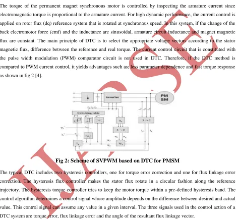
as shown in fig 2 [4].
Fig 2: Scheme of SVPWM based on DTC for PMSM
The typical DTC includes two hysteresis controllers, one for torque error correction and one for flux linkage error
correction. The hysteresis flux controller makes the stator flux rotate in a circular fashion along the reference
trajectory. The hysteresis torque controller tries to keep the motor torque within a pre-defined hysteresis band. The
control algorithm determines a control signal whose amplitude depends on the difference between desired and actual
value. This control signal can assume any value in a given interval. The three signals used in the control action of a
DTC system are torque error, flux linkage error and the angle of the resultant flux linkage vector.
IV FIELD ORIENTED CONTROL (FOC)
The field oriented control method is used in most of the AC motor drives to obtain high torque bandwidth and
control performance. The principle of field oriented control of electrical drives is based on the control of both the
277 | P a g e
currents and voltages are represented by vectors. In this control technique, some projections which transform a
three-phase speed dependent system into a two co-ordinate (d and q co-ordinates) time invariant system are used to
provide great simplification in expression of control equations. These transformations lead to a structure similar to
that of a DC machine control In Field Oriented Control the goal is to control the direct and quadrature axis current id
and iq to achieve the requested torque.
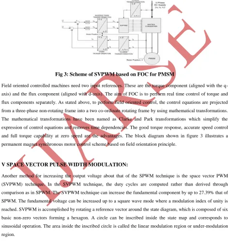
Fig 3: Scheme of SVPWM based on FOC for PMSM
Field oriented controlled machines need two input references. These are the torque component (aligned with the
q-axis) and the flux component (aligned with d-q-axis). The aim of FOC is to perform real time control of torque and
flux components separately. As stated above, to perform field oriented control, the control equations are projected
from a three-phase non-rotating frame into a two co-ordinate rotating frame by using mathematical transformations.
The mathematical transformations have been named as Clarke and Park transformations which simplify the
expression of control equations and removes time dependencies. The good torque response, accurate speed control
and full torque capability at zero speed are the advantages. The block diagram shown in figure 3 illustrates a
permanent magnet synchronous motor control scheme based on field orientation principle.
V SPACE VECTOR PULSE WIDTH MODULATION:
Another method for increasing the output voltage about that of the SPWM technique is the space vector PWM
(SVPWM) technique. In the SVPWM technique, the duty cycles are computed rather than derived through
comparison as in SPWM. The SVPWM technique can increase the fundamental component by up to 27.39% that of
SPWM. The fundamental voltage can be increased up to a square wave mode where a modulation index of unity is
reached. SVPWM is accomplished by rotating a reference vector around the state diagram, which is composed of six
basic non-zero vectors forming a hexagon. A circle can be inscribed inside the state map and corresponds to
sinusoidal operation. The area inside the inscribed circle is called the linear modulation region or under-modulation
278 | P a g e
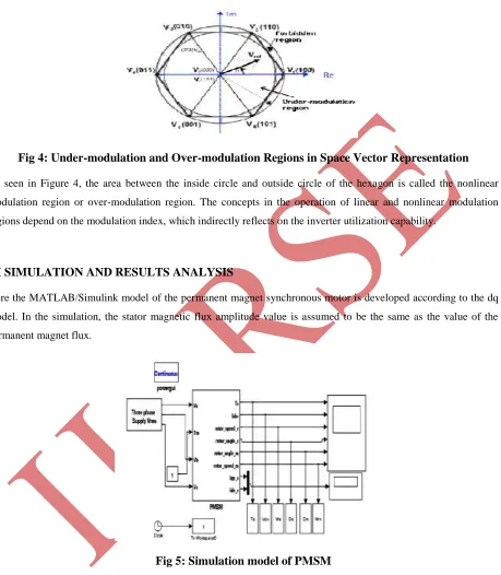
Fig 4: Under-modulation and Over-modulation Regions in Space Vector Representation
As seen in Figure 4, the area between the inside circle and outside circle of the hexagon is called the nonlinear
modulation region or over-modulation region. The concepts in the operation of linear and nonlinear modulation
regions depend on the modulation index, which indirectly reflects on the inverter utilization capability.
VI SIMULATION AND RESULTS ANALYSIS
Here the MATLAB/Simulink model of the permanent magnet synchronous motor is developed according to the dq
model. In the simulation, the stator magnetic flux amplitude value is assumed to be the same as the value of the
permanent magnet flux.
Fig 5: Simulation model of PMSM
CASE 1: SIMULATION MODELS OF FIELD ORIENTED CONTROL FOR PMSM BASED ON
279 | P a g e
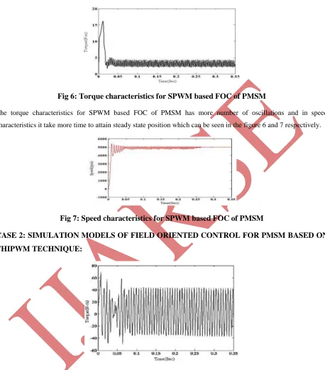
Fig 6: Torque characteristics for SPWM based FOC of PMSM
The torque characteristics for SPWM based FOC of PMSM has more number of oscillations and in speed
characteristics it take more time to attain steady state position which can be seen in the figure 6 and 7 respectively.
Fig 7: Speed characteristics for SPWM based FOC of PMSM
CASE 2: SIMULATION MODELS OF FIELD ORIENTED CONTROL FOR PMSM BASED ON
THIPWM TECHNIQUE:
Fig 8: Torque characteristics for THIPWM based FOC of PMSM
The torque characteristics for Third Harmonic Injection PWM based FOC of PMSM has more number of
oscillations compared to Sine PWM and in speed characteristics it has never attained a steady state position, as
280 | P a g e
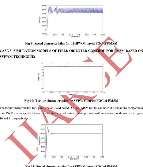
Fig 9: Speed characteristics for THIPWM based FOC of PMSM
CASE 3: SIMULATION MODELS OF FIELD ORIENTED CONTROL FOR PMSM BASED ON
SVPWM TECHNIQUE:
Fig 10: Torque characteristics for SVPWM based FOC of PMSM
The torque characteristics for Space Vector PWM based FOC of PMSM has less number of oscillations compared to
Sine PWM and in speed characteristics it has attained a steady state position with in no time, as shown in the figure
10 and 11 respectively.
Fig 11: Speed characteristics for SVPWM based FOC of PMSM
CASE 4: SIMULATION MODEL OF DIRECT TORQUE CONTROL FOR PMSM BASED ON
281 | P a g e
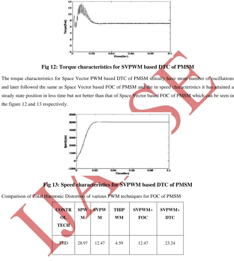
Fig 12: Torque characteristics for SVPWM based DTC of PMSM
The torque characteristics for Space Vector PWM based DTC of PMSM initially have more number of oscillations
and later followed the same as Space Vector based FOC of PMSM and the in speed characteristics it has attained a
steady state position in less time but not better than that of Space Vector based FOC of PMSM which can be seen in
the figure 12 and 13 respectively.
Fig 13: Speed characteristics for SVPWM based DTC of PMSM
Comparison of Total Harmonic Distortion of various PWM techniques for FOC of PMSM
CONTR OL TECH
SPW M
SVPW M
THIP WM
SVPWM+ FOC
SVPWM+ DTC
THD 28.97 12.47 4.59 12.47 23.24
VII CONCLUSION
Two control strategies are proposed for PMSM drive, field oriented control (FOC) using SVPWM, SPWM and
Third Harmonic Injection PWM and direct torque control (DTC) using SVPWM. The field oriented control (FOC)
field-282 | P a g e
oriented control, the reference currents of PMSM are calculated in terms of minimum torque ripples and fixed speed
operation. Thereupon, the difference between estimated and calculated reference currents are applied to choose a
proper switching vector based on SVPWM, and so as with the SPWM. But while considering the Third Harmonic
Injection PWM it is highly non-linear, so it increases the non-linearity of the system, so it cannot be used in
controlling the PMSM. While in direct torque control (DTC) method the flux and torque are calculated and
compared with the reference values using hysteresis comparators. Thereupon, the difference between estimated and
calculated reference torque values are applied to choose a proper switching vector using flux table based on
SVPWM, which is used to feed the inverter pulses so as to control the PMSM.
Several numerical simulations using MATLAB/SIMULINK have been carried out in steady-state and transient-state.
According to the results, the proposed techniques are able to reduce torque ripple, minimize speed error, and lessen
time to reach transient-state at abrupt mechanical load changes. In addition, we could have some other advantages
like, constant switching frequency, fast transient response, and tunable output torque and speed with lower error. But
considering the consistency of selecting the control technique for PMSM, on comparing both the techniques FOC
shows better performance in both torque and speed dynamics.
REFFERENCES
[1] M. S. Merzoug, and F. Naceri “Comparison of Field-Oriented Control and Direct Torque Control for Permanent Magnet Synchronous Motor (PMSM)” World Academy of Science, Engineering and Technology 21 2008
[2] S.Vaez-Zadeh, „High performance Control of Permanent Magnet Synchronous Motors‟, Tutorial Proposal for
MED 2007 Conference.
[3] Raja Ram Kumar, Sunil Kumar, Alok Yadav “Comparison of PWM Techniques and Inverter Performance,”
IOSR Journal of Electrical and Electronics Engineering (IOSR-JEEE), ISSN: 2278-1676 Volume 4, Issue 1
(Jan. - Feb. 2013), PP 18-22.
[4] Kiran Boby, Prof.Acy M Kottalil, N.P.Ananthamoorthy “Mathematical Modeling of PMSM Vector Control
System Based on SVPWM with PI Controller Using MATLAB” International Journal of Advanced Research in
Electrical, Electronics and Instrumentation Engineering Vol. 2, Issue 1, January
[5] M. Malek, J. Vittek, V. Vavrúš, M. Štulrajter ”Application Of Space Vector Modulation in Direct Torque Control Of PMSM” Advances in Electrical and Electronic Engineering.
[6] Jorge O. Estima and A. J. Marques Cardoso, „Impact of Inverter Faults in the Overall Performance of Permanent Magnet Synchronous Motor Drives‟, IEEE transactions, 2009.\
[4] Kiran Boby, Prof.Acy M Kottalil, N.P.Ananthamoorthy “Mathematical Modeling of PMSM Vector Control
System Based on SVPWM with PI Controller Using MATLAB” International Journal of Advanced Research in
283 | P a g e
[5] M. Malek, J. Vittek, V. Vavrúš, M. Štulrajter ”Application Of Space Vector Modulation in Direct Torque Control Of PMSM” Advances in Electrical and Electronic Engineering.
[6] Jorge O. Estima and A. J. Marques Cardoso, „Impact of Inverter Faults in the Overall Performance of Permanent Magnet Synchronous Motor Drives‟, IEEE transactions, 2009.
[7] M. Malek, J. Vittek, V. Vavrúš, M. Štulrajter ”Application Of Space Vector Modulation in Direct Torque Control Of PMSM” Advances in Electrical and Electronic Engineering.
[8] Joachim Boecker, „Modeling and Control of Permanent Magnet Synchronous Motors‟, Tutorial Proposal
EPE-PEMC, 2006.
[9] P. Brandstetter, P. Rech, and P. Simonik, „Sensorless Control of Permanent Magnet Synchronous Motor Using
Luenberger Variable Structure Speed Control System Using a Self-Controlled Synchronous Motor‟, IEEE
transactions on industrial electronics, APRIL 1990.Observer‟, PIERS Proceedings, Cambridge, USA, July 5-8,
2010.
[10] Pradeep K. Nandam, AND Paresh C. Sen, „A Comparative Study of a Luenberger Observer and Adaptive
Observer-Based
[11] Joohn-,Sheok Kim and Seung-,Ki SUI, „High Performance PMSM Drives without Rotational Position Sensors
Using Reduced Order Observer‟, IEEE transactions, 1995.
[12] Lennart Harnefors, Hans-Peter Nee, “A General Algorithm for Speed and Position Estimation of AC Motors”,
IEEE TRANSACTIONS ON INDUSTRIAL ELECTRONICS, VOL. 47, NO. 1, FEBRUARY 2000.
[13] P.Ramana, B.Santhosh Kumar, K.Alice Mary and M.Surya Kalavathi “Direct Torque Control Inverter Fed PMSM Drive using SVM” IJAIEM, Vol.2, Issue.7, pp.2928-2936.
AUTHOR 1:
Gangadhar Chandaka received his Bachelor of technology from EEE- Avanthi Institute of engineering & technology
(JNTUK, Kakinada), Vizag in 2011. He is currently pursuing Masters in Avanthi's Research &Tech Academy in the
department of Power Electronics and Drives. His area of interests are FACTs, Special Machines and Power
Electronics.
AUTHOR 2:
G Prasanth working as Assistant Professor at Avanthi's Research &Tech Academy, Vizag. He received his Masters
from Gayatrri Vidya Parishath, Vizag. He guided several UG projects PG projects. His areas of interests power