Theoretical and Simulation Studies on Water-Loaded Metal Diagonal
Horn Antenna for Hyperthermia Application
Soni Singh and Surya P. Singh*
Abstract—This paper is a continuation of our previous published work in which a water-loaded metal diagonal horn antenna has been designed at 2450 MHz for hyperthermia application and simulated results are compared with those measured. In the present study, theoretical investigations of Specific Absorption Rate (SAR) distribution in a homogeneous biological phantom (muscle) due to direct contact water-loaded metal diagonal horn antenna at 915 and 2450 MHz for hyperthermia application is presented. It is estimated theoretically that, at both the operating frequencies, a reasonable impedance matching is achieved at the interface between the antenna aperture and the biological phantom, where a computation of aperture admittance and reflection coefficient has been performed. Furthermore, it is confirmed through theoretical and simulation studies that the proposed horn antenna gives circularly symmetric SAR distribution in transverse plane in the biological phantom at 915 and 2450 MHz. The simulated and theoretical SAR distributions at 2450 MHz are compared with those determined at 915 MHz. In addition, thermal simulation results based on Pennes’ Bio-heat equation (BHE) are applied to the realistic muscle model at 915 and 2450 MHz. The reduction of blood flow rate on temperature distribution is also studied.
1. INTRODUCTION
Hyperthermia is one of the therapeutic non-invasive modalities considered for cancer treatment. Clinical trials have shown that a temperature in the range of 42–50◦C is required for hyperthermia treatment of cancer, while a temperature below 42◦C is preserved for surrounding healthy tissues. In the last few years, the focusing ability of microwave radiation has aroused considerable research interest in the bio-medical applications, including hyperthermia. Currently, various types of applicators are available for hyperthermia, but localized heating of larger tumors at greater depth needs to be further investigated [1– 14].
Recently, experimental and simulation studies of water-loaded metal diagonal horn antenna have been performed at 2450 MHz for hyperthermia application. It has been proved that the water-loaded horn antenna provides a circularly symmetric Effective Field size (EFS) [15]. Previous work performed measurements and simulation study on the diagonal horn antenna for hyperthermia at 2450 MHz. Furthermore, to heat larger spherical/near spherical tumors situated at greater depth, the applicator’s study can be performed at the lower ISM frequency of 915 MHz. The present investigation emphasizes on the theoretical estimation of SAR distributions in the muscle phantom and other related antenna parameters at two ISM frequencies of 915 MHz and 2450 MHz. A more rigorous thermal simulation study is also reported in the present paper.
Considering the foregoing statements, we have investigated the water-loaded diagonal horn applicator further. The objectives of this work are (i) to investigate theoretically, as well as through simulations, the SAR distribution in a biological phantom when a diagonal horn operating at 915 and
Received 6 May 2015, Accepted 2 July 2015, Scheduled 13 July 2015
* Corresponding author: Surya Pal Singh ([email protected]).
2450 MHz is applied, (ii) to compute theoretically the aperture admittance and hence the reflection coefficient, at the interface between the antenna and the phantom. These parameters are relevant in terms of coupling of electromagnetic energy with the biological phantom, (iii) to assess that the proposed horn antenna provides effective localized heating of the biological phantom.
All simulation studies have been carried out by using the software Computer Simulation Technology Microwave Studio (CST MWS) 2011, which is based on finite integration numerical technique [16]. The theoretical investigation of fields in the planar biological phantom due to water-loaded diagonal horn antenna makes use of plane wave spectral technique for computation of SAR distribution in the biological phantom. The theoretical field components, aperture admittance and SAR distributions were numerically evaluated by using MATLAB software. The results of SAR distributions obtained through theoretical investigations have been compared with those given in Ref. [15]. Additionally, the effects of input power and blood flow rate on the temperature distribution in a more realistic muscle model have also been simulated at both 915 and 2450 MHz.
2. MATERIALS, METHODS AND THEORY
2.1. Horn Antenna Design
The water-loaded metal diagonal horn antennas have been designed at 915 and 2450 MHz following the procedure similar to Love [17] for empty horn and that given in reference [15]. The complex permittivity of water has been taken to be 77 −j12.09 and 78 −j3.09 [12] at 915 and 2450 MHz respectively. Water-loaded horn antennas for operation at 915 and 2450 MHz have been assumed excited with higher frequency water-filled metal rectangular waveguides WR-112 and WR-34 [15] respectively.
The aperture dimension (d) of the water-loaded diagonal horn antenna has been selected for required gain (G), which can be found from the following relation [17]:
G= 10 log4πηd
2
λ2
w
(1)
whereηis the efficiency of the horn antenna, which can be taken equal to 0.81 [17], andλw(=λ/(
εrw) is the effective wavelength at the design frequency of the horn antenna, and εrw is the real part of the relative permittivity of water. Each horn antenna was designed for 15 dB gain.
The aperture dimension ‘d’ of the horn antenna has been computed using Equation (1). The dimension optimization of each water-loaded diagonal horn antenna has been carried out using CST MWS software.
The aperture of each diagonal horn antenna has been assumed to be surrounded by a conducting ground plane of copper inxy-plane so that the fringing electric field outside the aperture becomes zero. The dimensions of the conducting ground plane are 25×25×0.2 cm3, and 15×15×0.2 cm3 for the
diagonal horn antennas designed at 915 MHz and 2450 MHz respectively. TE10 mode propagates in
each input rectangular waveguide at the operating frequency. The input end of rectangular waveguide section of each horn antenna has been short circuited. Each diagonal horn antenna has been assumed to be excited with the help of coaxial probe inserted through a small hole cut in the middle of the broad wall of rectangular waveguide section at a distance of λgε/4 from the short-circuited end, whereλgε is
the guide wavelength in water-loaded input rectangular waveguide for TE10 mode given by the relation
λgε =
λw
1−
fc10 f
2 (2)
where fc10 (= c/2a
εrw) is the cut off frequency for TE10 mode, c (= 3×10⁸m/s) is the velocity of
microwave in free space, a is the broad dimension of the input rectangular waveguide, and f is the operating frequency.
d
x
y
z
L1
T1 T2
L d1
L2 L3 Probe
location
(a) (b) (c)
t3
t2 t1
Conducting ground plane Biological phantom
Figure 1. Structure of metal diagonal horn antenna. (a) Top view. (b) Side view. (c) Terminated in a biological phantom.
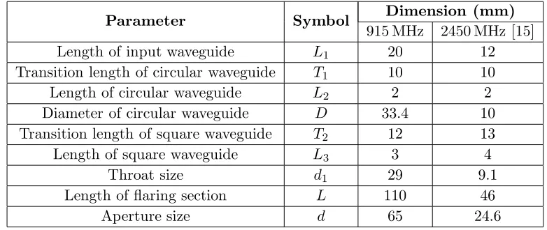
Table 1. Design parameters of water-loaded metal diagonal horn antenna.
Parameter Symbol Dimension (mm)
915 MHz 2450 MHz [15] Length of input waveguide L1 20 12
Transition length of circular waveguide T1 10 10
Length of circular waveguide L2 2 2
Diameter of circular waveguide D 33.4 10 Transition length of square waveguide T2 12 13
Length of square waveguide L3 3 4
Throat size d1 29 9.1
Length of flaring section L 110 46
Aperture size d 65 24.6
2.2. Theory
2.2.1. Analysis of Field Components inside the Biological Phantom (Muscle)
In order to quantify the induced electric field in a biological phantom (muscle) due to the known field distribution at the aperture of water-loaded diagonal horn antenna terminated in the bi-layered media consisting of muscle and free space layers, theoretical analysis has been presented. In the present analysis, the muscle layer is considered to be of finite thickness ‘t3’ followed by infinite free space layer.
Muscle phantom and free space layers have relative permittivities of ε∗1 andε2 respectively. The values
of complex relative permittivity of the biological phantom are 55.00−j19.00 [18] and 50.00−j16.00 [15] at 915 MHz and 2450 MHz respectively. The analysis of fields in bi-layered media presented here follows the plane wave spectral technique discussed by Compton [19] and Harrington [20].
Previously, plane wave spectral technique was used to estimate the induced field components in the biological phantom due to the box-horn [12] for which aperture field varies along one direction only, while the field remains constant along the transverse direction as given in [12, 19, 20]. However, in case of the proposed horn antenna, aperture field varies in bothx- andy-directions due to the propagation of TE10 and TE01 orthogonal modes. The aperture of the proposed horn antenna is assumed to be
surrounded by conducting ground plane in xy-plane, so that the fringing field outside the aperture becomes zero and back lobes disappear. The proposed horn is a multimode horn antenna in which TE10
and TE01modes are present at the aperture. In the present theoretical analysis, it is assumed that only
TE10 and TE01 mode fields are present at the aperture and also aperture phase error is zero.
is represented by
Ex1(x, y,0) =a10(1 + Γ) cos
πy
d
(3)
Ey1(x, y,0) =a01(1 + Γ) cos
πx
d
(4) where a10 and a01 are amplitude coefficients, and Γ is reflection coefficient at the interface between
water-loaded diagonal horn antenna and biological phantom (muscle).
When the aperture electric field is given by Equations (3) and (4), the field in the bi-layered media (muscle and free-space layers) are everywhere TE to x and TE to y [19]. Through the use of ‘plane wave spectral technique’ as given in references [19, 20], spectral integral representations of the fields in the different layers are obtained. Thex-, andy-components of electric and magnetic fields in the muscle layer and free space layer are obtained as given in the reference [12] are reproduced below.
Ex1(x, y, z) =
1 2π2
∞ −∞ ∞ −∞
−jkz1Iψ1e−jkz1z+jkz1Rψ1ejkz1z e−jkxxe−jkyydkxdky (5)
Ey1(x, y, z) =
1 2π2
∞ −∞ ∞ −∞
jkz1Iφ1e−jkz1z−jkz1Rφ1ejkz1z e−jkxxe−jkyydkxdky (6)
Hx1(x, y, z) =
1 2π2
∞ −∞ ∞ −∞
k21−k2x jωμ0
Iφ1e−jkz1z+Rφ1ejkz1z
−kxky jωμ0
Iψ1e−jkz1z+Rψ1ejkz1z e−jkxxe−jkyydkxdky (7)
Hy1(x, y, z) =
1 2π2
∞ −∞ ∞ −∞
k21−k2y jωμ0
Iψ1e−jkz1z+Rψ1ejkz1z
−kxky jωμ0
Iφ1e−jkz1z+Rφ1ejkz1z e−jkxxe−jkyydkxdky (8)
Similarly, thez-component andx-,y- andz-components of electric and magnetic fields in the biological phantom and free space layers are derived.
By taking the inverse Fourier transform of Equations (5) and (6) atz= 0, we get
jkz1 [−Iψ1+Rψ1] =f (9)
where,
f=
d/2
−d/2
d/2
−d/2
a10(1+Γ) cos
πy
d
ejkxxejkxydxdy=4πda10(1+Γ)
kx
π2−k2
yd2
sin
kxd
2
cos
kyd
2
jkz1[Iφ1−Rφ1] =g
(10)
where,
g=
d/2
−d/2
d/2
−d/2
a01(1 + Γ) cos
πx
d
ejkxxejkxydxdy= 4πda01(1 + Γ)
ky(π2−kx2d2)
sin
kyd
2
cos
kxd
2
By applying the boundary condition, i.e., the continuity of tangential electric and magnetic fields at ‘z = t3’ (the interface between muscle and free-space), remaining four equations are determined as
follows:
jkz1Iφ1e−jkz1t3−jkz1Rφ1ejkz1t3=jkz2Tφ1e−jkz2t3 (12)
k12−k2xIφ1e−jkz1t3+Rφ1ejkz1t3 −kxky
Iψ1e−jkz1t3+Rψ1ejkz1t3 =k22−kx2Tφ1e−jkz2t3−kxkyTψ1e−jkz2t3 (13)
k2
1−k2y
Iψ1e−jkz1t3+Rψ1ejkz1t3 −kxky
Iφ1e−jkz1t3+Rφ1ejkz1t3 =k22−k2x
Tψ1e−jkz2t3−kxkyTφ1e−jkz2t3 (14)
The expressions for Rψ1 and Rφ1 obtained from Equations (9) and (10) are substituted into
Equations (11)–(14) and the resulting equations are expressed as follows:
A11Iφ1+A12Iψ1 =B11 (15)
A21Iφ1+A22Iψ1 =B22 (16)
A11=
k12−kx2kz2coskz1t3+j
k22−k2xkz1sinkz1t3 (17)
A12=A21=−kxky(kz2coskz1t3+jkz1sinkz1t3) (18)
A22=
k12−ky2kz2coskz1t3+j
k22−ky2kz1sinkz1t3 (19)
B11=−2j
gkz2 kz1e
jkz1t3k2 1−k2x
+kxkyf ejkz1t3+f kxkykkzz21ejkz1t3+gejkz2t3
k22−k2x(20)
B22=j2
fkz2 kz1e
jkz1t3k2 1−k2y
+gkxkykkzz21ejkz1t3+gkxkyejkz1t3+f ejkz2t3
k2 2 −ky2
(21)
Iφ1 =
B11 A12
B22 A22
A11 A12
A21 A22
, Iψ1 =
A11 B11
A21 B22
A11 A12
A21 A22
(22)
Once the solution for Iφ1 and Iψ1 are obtained by using Equation (22), other plane wave spectra such
asRψ1,Rφ1,Tψ1 and Tφ1 can be determined using Equations (11)–(14).
The x-, y- and z-components of electric field in the muscle layer can then be found by using Equations (5)–(6). The resultant electric field intensity in the muscle phantom is given by
|E|2=|Ex1|2+|Ey1|2+|Ez1|2 (23)
The Specific Absorption Rate (SAR) in the phantom muscle can be evaluated by
SAR= σ|E|
2
2ρ (24)
where, |E|is the magnitude of total induced electric field strength inside the biological phantom, and
σ and ρ are the conductivity and density of the biological phantom respectively.
2.2.2. Determination of Aperture Admittance and Reflection Coefficient at the Interface between Antenna Aperture and Biological Phantom
The aperture admittance of water-loaded diagonal horn antenna terminated in a phantom muscle is given by [19]
YA= d/2
−d/2
d/2
−d/2
Ex1(x, y,0)·Hy∗1(x, y,0)−Ey1(x, y,0)·Hx∗1(x, y,0)
dxdy (25)
where, Ex1(x, y,0), Ey1(x, y,0) and Hx∗1(x, y,0), Hy∗1(x, y,0) are electric and magnetic fields at the
aperture (z= 0) respectively, which can be obtained by using Equations (5), (6), (7) and (8).
Reflection at any interface (separating the two media) is the result of impedance mismatch, which occurs due to change in physical properties of two media. Therefore, the reflection coefficient at the interface between proposed horn antenna and biological phantom can be written as:
Γ = ZA−Z0
ZA+Z0
(26)
whereZA(= 1/YA) is the aperture impedance of the antenna,Z0 (= 120π
μ∗w ε∗w ·
λgε
λw) is the characteristic
3. RESULTS AND DISCUSSION
3.1. SAR Distribution in the Biological Phantom
The applicator’s design data along with dielectric properties of biological phantom discussed in Section 2.1, and given in Table 1 have been used in the estimation of theoretical and simulated SAR distributions at the two operating frequencies of 915 and 2450 MHz. The density of biological phantom was chosen to be 1050 kg/m3. In the present analysis, biological phantom (muscle layer) is considered to be of finite thickness. The theoretical relative SAR distributions in the muscle phantom were obtained by numerically solving the equations given in Section 2.2 using MATLAB software and the results are given in Figures 2 and 3. In order to validate the circular symmetric behavior of SAR distribution in the biological phantom due to the proposed horn antenna at 2450 MHz, normalized SAR distribution inxy -plane was obtained through theoretical analysis atz= 1 cm and the results are shown in Figure 3. These results clearly demonstrate the circular symmetry property of the SAR distribution in the biological phantom. Normalized SAR distribution at 915 MHz inxy-plane can be found, but is omitted here for the sake of brevity.
The simulated relative SAR distributions inside the biological phantom (muscle phantom) of size
t1×t2×t3 (= 200×200×150 mm3 at 915 MHz and 112×112×80 mm3 at 2450 MHz [15]) due to the
water loaded diagonal horn antennas were determined using CST MWS software. Initially, power fed to the antenna was assumed to be 1 W in the simulation study. The relative SAR distributions in the phantom muscle phantom were obtained by normalizing the SAR values with respect to the maximum value of SAR that occurs in the muscle phantom.
It can be seen from Figure 2 that the simulated and theoretical SAR distributions are nearly in agreement with each other. Thus, the validity of plane wave spectral technique is proved through simulated SAR distributions. It can also be observed from Figure 2 and Table 2 that theoretical results of SAR distribution are deviating to a smaller degree from the corresponding simulated results. The
i o l o g i c a l p h a n
0 10 20 30 40 50 Depth inside the biological phantom (mm)
Theoretical 2450 MHz Simulated 2450MHz [15] Theoretical 915 MHz Simulated 915 MHz
-40 -20 0 20 40 Along x-/y-directions (mm)
Theoretical 2450 Simulated 2450 MHz [15] Theoretical 915 MHz Simulated 915 MHz
(a) (b)
0 0.2 0.4 0.6 0.8 1
Normalized SAR
0 0.2 0.4 0.6 0.8 1
Normalized SAR
MHz
Figure 2. Relative SAR distributions inside the biological phantom due to water loaded metal diagonal horn antenna at 915 MHz and 2450 MHz along (a)z-direction (x=y= 0). (b)x-/y-direction atz= 1 cm (y-/x-= 0).
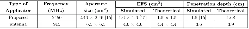
Table 2. SAR parameters in the biological phantom due to the proposed horn antenna at 915 and 2450 MHz.
Type of Applicator
Frequency (MHz)
Aperture size (cm2)
EFS (cm2) Penetration depth (cm) Simulated Theoretical Simulated Theoretical Proposed
antenna
2450 2.46×2.46 [15] 1.6×1.6 [15] 1.5×1.5 1.5 [15] 1.68
Normalized SAR
Biological phantom
Figure 3. Theoretical SAR distribution inside the biological phantom at 2450 MHz due to water-loaded metal diagonal horn antenna inxy-plane at
z= 1 cm.
0 15 30 45 60
0 10 20 30 40
Absolute SAR (W/kg)
Depth inside the biological phantom (mm) 2 W 10 W
Figure 4. Simulated absolute SAR distributions inside the biological phantom due to water loaded metal diagonal horn antenna at 915 MHz alongz -direction (x=y= 0) by taking input power as a parameter.
deviation in the results may be due to the factors given in the following. In theoretical analysis, conducting ground plane surrounding the proposed horn antenna aperture extends upto infinity while finite size of the conducting ground plane has been taken in simulation studies. The effect of generation of higher order modes near the discontinuity regions including the aperture of the proposed horn antenna is not considered in the theoretical analysis. Although these factors individually may not cause much effect on the SAR value, but when taken collectively, they may become significant cause of deviation between the theoretical and simulated SAR values.
Figure 2(a) illustrates the relative SAR distribution in the homogeneous biological phantom in
z-direction due to the water-loaded diagonal horn antennas operating at 915 MHz and 2450 MHz. The theoretical and simulated values of penetration depth in biological phantom (depth where SAR value is down to 13.5 percent of the maximum in the muscle) extracted from Figure 2(a) are given in Table 2 for diagonal horn antenna designed at 915 and 2450 MHz. It can also be observed from Table 2 that penetration depth is higher for the antenna designed at lower frequency.
The EFS is defined as the area that is enclosed within 50% SAR contour inside the biological phantom. Resolution of the applicator in transverse directions is represented by EFS and for high transverse resolution, the value of EFS must be small. The simulated and theoretical values of EFS extracted from Figure 2(b) due to the proposed horn antenna at each frequency are given in Table 2. It can be observed from Figure 2(b) and Table 2 that theoretical and simulated values of EFS are small and exhibit circular symmetry at 915 and 2450 MHz. The diagonal horn which is a multimode horn antenna supporting TE10and TE01modes has identical aperture field distribution inE- andH-planes.
That is why, circularly symmetric EFS is obtained due to the proposed horns at both the frequencies. It can also be seen from Table 2 that the simulated and theoretical values of EFS are significantly higher at 915 MHz as compared to those at 2450 MHz.
Figure 4 depicts the simulated absolute SAR distributions along z-direction in the biological phantom at 915 MHz by taking input power level as a parameter. It can be observed from Figure 4 that peak SAR value increases with input power level and SAR value decays exponentially at a rate equal to twice the decay rate for electric field.
Therefore, it can be inferred from the present study that the lower frequency applicator can be used for effective heating of spherical/near spherical tumors situated at greater depth.
3.2. Applicator’s Characteristics
Table 3. Estimated parameters from theoretical analysis.
Parameter Frequency (MHz)
2450 915
Aperture admittance (mho) 0.0178 +j0.0019 0.0185 +j0.0028 Aperture impedance (Ω) 55.59−j5.78 52.95−j8.097 Aperture reflection coefficient
(at the interface of aperture and biological phantom)
0.131−j0.05 0.0919−j0.07
interface of the proposed horn antenna and muscle phantom indicates that reasonably good impedance matching between the horn aperture and the biological phantom is achieved at both the frequencies, though matching is better at 915 MHz.
The simulated values of input reflection coefficient of the proposed antenna terminated in a biological phantom are−33 dB (= 0.02) and−17 dB (= 0.14) at 915 MHz and 2450 MHz [15] respectively, which indicates good matching of the applicator to the feed at both operating frequencies.
3.3. Simulation of Temperature Distribution
The applicator’s hyperthermia performance is characterized by the resulting temperature distribution in the realistic muscle medium. The heat generated due to the electromagnetic energy absorbed in the muscle medium is proportional to SAR. The bio-heat equation represents the relationship between the rate of electromagnetic energy absorbed into the tissue and the increase in tissue temperature. Therefore, the temperature distribution inside the realistic muscle model can be evaluated by using Pennes’ bio-heat equation (BHE) [21], which can be written as
ρC∂T
∂t =∇ ·(K∇T) +A0+ρSAR−B(T−TB) (27)
where ρ is the muscle density,C is the specific heat of muscle, K the muscle thermal conductivity,A0
the metabolic heat production, B the heat exchange mechanism due to capillary blood perfusion, and
TB the blood temperature assumed to be a constant (= 37◦C) equal to normal body temperature. The
thermal parameters used in Equation (27) are defined in Table 4.
In order to characterize the hyperthermia treatment system, the proposed applicator was used to feed microwave power to the muscle medium at 915 and 2450 MHz as shown in Figure 1(c). The thermal simulation was performed using CST multi-physics simulator [16] software by taking initial muscle temperature of 37◦C. The thermal parameters of the muscle used in simulation are listed in Table 4.
To observe the effect of blood flow rate on temperature distribution produced in the muscle phantom due to the proposed horn antenna at 915 and 2450 MHz, three kinds of muscle models were considered. First model involves the tissue with normal blood flow rate B of 2700 W/m3◦C. In the second model the muscle tissue was assumed to have reduced blood flow rate ofB/2, while in the last tissue model, blood flow rate is reduced to B/4 (tumor tissue) [8]. Simulation was performed for input power of 2 W at 2450 MHz while input power levels of 2 W and 10 W were assumed for simulation at 915 MHz.
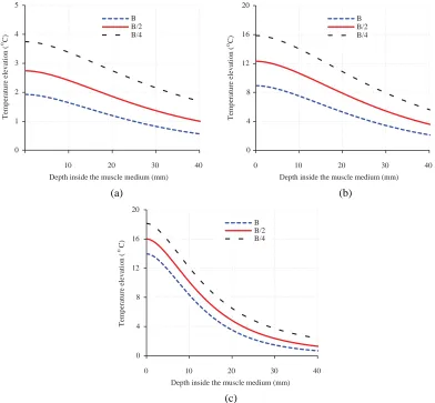
Figures 5(a), 5(b) and 5(c) show the profiles of temperature elevation at 915 and 2450 MHz due to the proposed horn antenna as functions of depth in the realistic muscle medium by taking blood flow rate as a parameter. It can be seen from Figure 5(a) and Table 5 that temperature elevation in
Table 4. Thermal parameters of muscle for the BHE [22].
ρ (kg/m3) C (KJ/Kg◦C) K (W/m◦C) A0 (W/m3) B (W/m3◦C)
10 20 30 40 Depth inside the muscle medium (mm)
B B/2 B/4
0 10 20 30 40
Depth inside the muscle medium (mm) B B/2 B/4
0 10 20 30 40
Depth inside the muscle medium (mm) B B/2 B/4
(a) (b)
(c)
0 1 2 3 4 5
Temperature elevation ( C)
0 4 8 12 16 20
0 4 8 12 16 20
Temperature elevation ( C)
o
o
Temperature elevation ( C)
o
Figure 5. Temperature elevation distribution in the realistic muscle medium heated by proposed horn antenna (normal surface temperature was assumed to be 37◦C) designed at (a) 915 MHz (input power = 2 W) (b) 915 MHz (input power = 10 W) (c) 2450 MHz (input power = 2 W).
Muscle medium Muscle medium Muscle medium
x x
y
x y y
Blood flow=B/2
Blood flow=B Blood flow=B/4
Muscle medium
x y
Blood flow=B
Muscle medium
x y
Blood flow=B/2
Muscle medium
x y
Blood flow=B/4 (a)
(b)
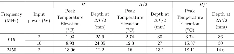
Table 5. Temperature elevation in the realistic muscle model due to the proposed applicator designed at 915 and 2450 MHz.
Frequency (MHz)
Input power (W)
B B/2 B/4
Peak Temperature
Elevation (◦C)
Depth at ΔT/2 (mm)
Peak Temperature
Elevation (◦C)
Depth at ΔT/2 (mm)
Peak Temperature
Elevation (◦C)
Depth at ΔT/2 (mm)
915 2 1.93 25.9 2.74 30 3.74 36
10 8.93 24.05 12.3 27 15.87 30
2450 2 13.96 12.2 16 13.1 18.11 14.6
the tissue due to the proposed horn antenna designed at 915 MHz and fed with 2 W input power is not sufficient for proper hyperthermia performance. Hence power inputted to the applicator designed at 915 MHz was increased to 10 W to raise the temperature of cancerous tissue (situated at greater depth) adequately for effective hyperthermia (Figure 5(b) and Table 5).
It is noticed from Figures 5(a), 5(b) and 5(c) that at a given frequency, temperature elevation in the muscle tissue increases with decrease in blood flow rate. Further, temperature elevation decreases exponentially with depth in the muscle medium at a given frequency. The values of peak temperature elevation and the depth at which temperature elevation reduces to half of the maximum extracted from Figures 5(a), 5(b) and 5(c) are also given in Table 5.
Figures 6(a) and 6(b) show the profiles of temperature distribution inside the realistic muscle medium at z= 1 cm for optimum input power levels (10 W at 915 MHz and 2 W at 2450 MHz) due to the proposed applicator. Symmetrical temperature distribution in the biological phantom due to the proposed applicator can be observed in the transverse xy-plane.
These results corroborates the annotation that spherical/near spherical tumor volume (in which scanty blood flow is there) can be effectively heated as compared to normal tissue using an applicator of the sort proposed here. From this study, it can be said that cancerous tissue can be heated to higher temperature as compared to normal tissue for same input power.
4. CONCLUSION
Water-loaded metal diagonal horn antenna has been investigated through simulation and theoretically for hyperthermia application at 915 and 2450 MHz. The study involves determination of theoretical SAR distributions in the muscle phantom due to the proposed applicator designed at 915 MHz and 2450 MHz and comparison with the corresponding simulated ones. The water loaded diagonal horn antenna designed at 915 MHz gives higher penetration depth and lower transverse resolutions inside the phantom muscle as compared with the diagonal horn antenna designed and developed at 2450 MHz. Results obtained through theoretical study indicates that reasonably good impedance matching between the antenna aperture and the biological phantom has been obtained at both the frequencies. In addition results obtained through thermal simulation on realistic muscle model suggests that heating pattern could be controlled by varying the input power and blood flow rate. Also, the temperature distribution obtained in muscle tissue through thermal simulation indicates that the proposed horn antenna can be used as effective hyperthermia applicator for spherical tumors in superficial regions of the body assuming that blood flow in the tumor region is significantly reduced as compared with normal tissue region. The study presented here can be used to design an appropriate diagonal horn applicator for hyperthermia.
REFERENCES
2. Lehmann, J. F., A. W. Guy, J. B. Stonebride, and B. J. DeLateur, “Evaluation of a therapeutic direct contact 915 MHz microwave applicator for effective deep-tissue heating in humans,” IEEE Trans. Microw. Theory Tech., Vol. 26, 556–563, 1978.
3. Stuchly, M. A., S. S. Stuchly, and G. Kantor, “Diathermy applicators with circular aperture and corrugated flange,” IEEE Trans. Microw. Theory Tech., Vol. 28, 267–271, 1980.
4. Van Rhoon, G. C., P. J. Rietveld, and J. Van der Zee, “A 433 MHz lucite cone waveguide applicator for superficial hyperthermia,”Int. J. Hyperthermia, Vol. 14, 13–27, UK, 1998.
5. Lin, J. C., G. Kantor, and A. Ghods, “A class of new microwave therapeutic applicators,” Radio Science, Vol. 17, 119S–123S, 1982.
6. Nikawa, Y., H. Watanabe, M. Kikuchi, and S. Mori, “A direct-contact microwave lens applicator with a microcomputer-controlled heating system for local hyperthermia,” IEEE Trans. Microw. Theory Tech., Vol. 34, 626–630, 1986.
7. Kantor, G. and D. M. Witters, “A 2450 MHz slab-loaded direct contact applicator with choke,”
IEEE Trans. Microw. Theory Tech., Vol. 28, 1418–1422, 1980.
8. Nikawa, Y. and F. Okada, “Dielectric-loaded lens applicator for microwave hyperthermia,” IEEE Trans. Microw. Theory Tech., Vol. 39, 1173–1177, 1991.
9. Uzunoglu, N. K., E. A. Angelikas, and P. A. Cosmidis, “A 432 MHz local hyperthermia system using an indirectly cooled water-loaded waveguide applicator,”IEEE Trans. Microw. Theory Tech., Vol. 35, 106–111, 1987.
10. Nikita, K. S. and N. K. Uzunoglu, “Analysis of the power coupling from a waveguide hyperthermia applicator into a three-layered tissue model,” IEEE Trans. Microw. Theory Tech., Vol. 37, 1794– 1800, 1989.
11. Gupta, R. C. and S. P. Singh, “Analysis of the SAR distributions in three layered bio-media in direct contact with a water-loaded modified box-horn applicator,” IEEE Trans. Microw. Theory Tech., Vol. 53, 2665–2671, 2005.
12. Gupta, R. C. and S. P. Singh, “Development and analysis of a microwave direct contact water-loaded box-horn applicator for therapeutic heating of bio-medium,” Progress In Electromagnetics Research, Vol. 62, 217–235, 2006.
13. Ebrahimi-Ganjeh, M. A. and A. R. Attari, “Study of water bolus effect on SAR penetration depth and effective field size for local hyperthermia,” Progress In Electromagnetics Research B, Vol. 4, 273–283, 2008.
14. Kantor, G., D. M. Witters, and J. W. Greiser, “The performance of a new direct-contact applicator for microwave diathermy,”IEEE Trans. Microw. Theory Tech., Vol. 26, 563–568, 1978.
15. Singh, S. and S. P. Singh, “Water-loaded metal diagonal horn applicator for hyperthermia,” IET Microwaves, Antennas and Propagation, Vol. 9, No. 8, 814–821, 2014.
16. CST [MWS], Online, Available: http://www.cst.com.
17. Love, A. W., Electromagnetic Horn Antennas, IEEE Press, New York, 1976.
18. Gabriel, C., “Compilation of the dielectric properties of body tissues at RF and microwave frequencies,” Tech. Rep. AL/OE-TR-1996-0037, Brooks AFB, TX, 1996.
19. Compton, R. T., “The admittance of aperture antenna radiating into lossy media,” Rep. 1691-5, Antenna Laboratory Ohio State University Research Foundation Columbus, Ohio, 1964.
20. Harrington, R. F., Time-harmonic Electromagnetic Field, McGraw-Hill Book Company, 123–135, New York, 1961.
21. Pennes, H. H, “Analysis of tissue and arterial blood temperatures in the resting human forearm,”
J. Appl. Physiol., Vol. 85, 5–34, 1998.
22. Gong, Y. and G. Wang, “Superficial tumor hyperthermia with flat left-handed metamaterial lens,”