Study of Multi-Band Circularly Polarized Microstrip
Antenna with Compact Size
Kun Wei*, Jian-Ying Li, Ling Wang, Zi-Jian Xing, and Rui Xu
Abstract—In some satellite navigation receiver systems, there is not enough space to settle several antennas for multi-port multi-band application generally. A triple-deck circularly polarized antenna with three ports for receiving and sending satellites signal is studied in this paper. The design idea in this paper is to place several single-feed microstrip antennas layer by layer for saving space. All patch antennas are probe-fed, and the probe connected with the upper patch goes through the clear hole in lower substrates. The structure of the multi-band antenna is investigated thoroughly. How to tune this kind of antenna is a big problem in application, and one special parameter is given to adjust the performance of the antenna. The designed triple-deck antenna works at the bands of GPS, BDS and 1.66 GHz independently. The formal two bands are RHCP, and the third band is LHCP, so it can receive and send signals at the same time. Both simulated and measured results show that all three working bands can cover the system use differently. Axial ratio less than 3 dB at center frequency is obtained, and absolute gain at center frequency is more than 4 dBic. The advantages of this antenna are compact in size for multi-port multi-band use and easy fabrication.
1. INTRODUCTION
Over the last few years, the applications of Global Positioning System (GPS) and BeiDou Navigation Satellite System (BDS) have increased considerably, such as geodetic surveying, aircraft landing control, and satellite attitude determination. The multi-band circular polarization antenna is becoming more and more important in systems as in [1, 2]. And multi-port multi-band CP microstrip antenna is needed in those multi-functional systems for application.
There are many kinds of circular polarization (CP) antennas introduced as in [3]. One popular CP antenna is microstrip antenna, which is widely used in both military and civil applications because of the advantages as: small size, low cost, easy manufacture, and convenience in expanding into arrays. Studies on CP microstrip antenna have been reported in [4, 5].
The structure of CP microstrip antenna can be mainly classified into three categories: single-fed antenna in [6], dual-fed microstrip antenna in [7] and sequential array in [8]. Single-fed CP microstrip antenna is with the simplest structure among the three types, because it does not require external circuitry to excite CP mode.
Multi-band CP microstrip antenna can be attained by stacked patches, trim slotted patch, etc. However, the stacked antenna operating at three working bands in [9] is linear polarization. Stacked antennas which are circularly polarized in several bands in [10] and antenna in paper [11] are with only one port. Multi-layer microstrip antenna in [12] is with only one port and not circularly polarized. Trim slotted antenna in [13] is with three resonators sharing single common feed, and short-circuit probe is not circularly polarized. Trim slotted triple-band CP antenna in [14] is with complex design. Dual-frequency dual-polarized slot-coupled compact microstrip antenna for communication systems is
Received 29 April 2015, Accepted 5 June 2015, Scheduled 19 June 2015
* Corresponding author: Kun Wei ([email protected]).
presented in [15], but not for multi-port application. Dual-band microstrip antenna with shorting pin in [16] is compact in size and with a simple structure, but it is not circularly polarized.
The study in this paper focuses on multi-port multi-band stacked CP microstrip antenna for practical application. Truncated corner microstrip antenna is taken into consideration because of its simplest structure. Software HFSS is employed for studying the new designed multi-port multi-band stacked CP microstrip antenna. A dual-band stacked antenna is studied to show that each layer resonates and works independently. And a triple-band antenna is designed by using the same structure. Both simulated and measured results show that all three working bands can cover the system use differently. Absolute gain at center frequency is more than 4 dBic, and axial ratio less than 3 dB at center frequency is obtained.
This paper is organized as follows. Some background about the satellite system and the research of multi-band CP microstrip antenna are placed in Section 1. The structure and analysis of the designed antenna are showed in Section 2. Simulated and measured results of designed antenna can be found in Section 3. Section 4 is about the conclusion of this paper.
2. ANALYSIS OF THE MULTI-BAND ANTENNA
The goal of the design in this paper is the compact-size multi-port multi-band CP microstrip antenna. The antenna works at three bands and covers three different systems applications, namely F1: BDS; F2: GPS-L1; F3: 1.66 GHz. The F1 and F2 bands require right-hand circularly polarized (RHCP), and the F3 band is left-hand circularly polarized (LHCP). The new designed antenna contains three layers. The bottom layer works at F1 band; middle layer works at F2 band; top layer works at F3 band.
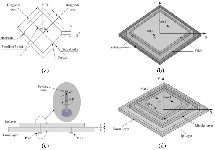
Circular polarization can be achieved with a single feed patch. Figure 1(a) shows the structure of a classical truncated corner single-feed microstrip antenna which is to trim the ends of two opposite corners of a square patch. Feeding the patch at a single point excites two orthogonal degenerate modes of ideally equal amplitudes, one mode increasing with frequency while the orthogonal mode will decrease with frequency by the same amount. By proper design, the field of one mode can lead by 45 deg while that of the other can lag by 45 deg, because a 90 deg phase difference for circular polarization will be obtained.
(a) (b)
(c) (d)
In the broadside direction of the patch, there is an electric linearly polarized far-fieldEx in the x direction and an electric linearly polarized far-field Ey in the y direction. In order to achieve circular polarization, the magnitude of the axial ratio must be unity while the phase must be±90 deg. Feeding the element along the diagonal one, ideally left-hand circular polarization is yielded. Right-hand circular polarization can be achieved by feeding along the opposite diagonal two. So if the feeding point rotates 135 deg or 315 deg counterclockwise from positive X axle, then the antenna will be LHCP, and the antenna will be RHCP if the feeding point rotates 45 deg or 225 deg counterclockwise.
The dielectric constant isε; thickness of the substrate is T; size of the patch isS; position of the feeding point isP; the length of the truncated corner isL. The angle (A) discussed in this paper is the feeding point which rotates around center point.
Figure 1(b) shows the dual-band patch antenna works at F1 and F2 bands. The bottom layer antenna works at F1 band, and top layer antenna works at F2 band. The top layer of the dual-band antenna is fed using a probe electrically connected to the top square patch through a clearance hole of radius r = 0.5 mm in both top and bottom substrates as shown in Figure 1(c), and a circle radius
R = 3 mm is trimmed off from the bottom layer patch for avoiding unnecessary coupling, so two layered antennas are resonating and working independently. Port1 and port2 rotate 45 deg and 225 deg counterclockwise from positiveX axle differently, so both bottom and top layer antennas are RHCP as discussed before. The substrates of the two layers are selected with the same dielectric constant ε= 3 and same thickness T = 4 mm.
The structure of the designed triple-band antenna is the same as the dual-band antenna shown in Figure 1(d), just adding a third microstrip patch on the top of the dual-band antenna. And feeding probe of top layer goes through the clearance holes in the three layered substrates. circles radiiR= 3 mm are trimmed off from both bottom and middle layer patches. And port3 rotates 135 deg counterclockwise
(a) (b)
Figure 2. (a)S11 of the BDS antenna. (b)S11 of the GPS antenna when L2 is with different values.
(a) (b)
(a) (b)
Figure 4. (a) AR of the BDS antenna. (b) AR of the GPS antenna whenL2 is with different values.
Figure 5. S11 of the upper layer when A3
changes.
Figure 6. AR of the upper layer when A3
changes.
from positiveX axle, so top layer is LHCP. For simplicity, using 1, 2, 3 to indicate bottom, middle, top layers of the triple-band CP microstrip antenna, respectively.
The analysis of L2 (length of the truncated corner) of the dual-band antenna is discussed in the
paper because it is the key parameter to generate circular-polarized wave. Performances of S11, gain
and axial ratio of the dual-band antenna, whenL2 is given several values, are shown from Figure 2 to
Figure 4. When the value of L2 is changed, there is barely effect on the bottom layer. Parameter L2
only affects the axial ratio of F2 band antenna, so L2 is independent from F1 band antenna. And F2
band antenna works best when L2= 5.5 mm.
The process of tuning the antenna is to adjust each layer from bottom to top one by one. The bottom and middle layers have the same characteristics as the dual-band antenna mentioned before. So the faced challenge is how to tune the top layer. It is difficult to get great performance of the LHCP characteristic of the F3 band. Parameter A3 is brought up to overcome this difficulty.
Figure 5 and Figure 6 show S11 and axial ratio of the top layer change with the frequency when
A3 is with different values. The working frequency band moves to the top frequency whenA3 becomes
bigger, and the best performance point of the axial ratio moves to lower frequency at the same time. So the value of A3 is optimized for adjustingS11 and axial ratio of the up layer antenna.
3. DESIGN AND MEASUREMENT
The optimized parameters of the designed triple-band antenna are: the bottom layer, S1 = 73.5 mm,
P1 = 17 mm, A1 = 45 deg, L1 = 6.5 mm; the middle layer (works at F2 = 1.57542 GHz band),
S2 = 55.6 mm, P2 = 11.3 mm, A2 = 225 deg, L2 = 3.5 mm; the top layer (works at F3 = 1.66 GHz
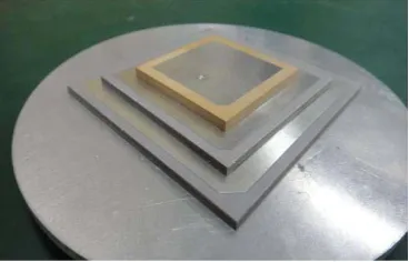
band), S3 = 35 mm, P3 = 9.2 mm, A3 = 127 deg, L3 = 3.5 mm. Object of the designed triple-band
Figure 7. The designed antenna object.
(a) (b)
Figure 8. (a) SimulatedS11, (b) measuredS11 of the designed triple-band antenna.
Figure 9. S12of the designed triple-band antenna.
Figure 8(a) shows the simulatedS11 of the triple-band stacked antenna. The simulated bandwidth
(S11<−10 dB) of the bottom layer is 50 MHz, and those of the middle and top layers are 30 MHz and
90 MHz, respectively, which can cover system application because each usable frequency band is less than 20 MHz. Figure 8(b) shows the measuredS11, and the middle layer works in two bands, but the
bottom one is spurious because of the coupling effect from the bottom layer because both bottom and middle layers are RHCP.
By loading the substrate, compact size of the designed antenna is obtained, but that will affect the performance of single layer antenna. S12 of the designed antenna is shown in Figure 9. S12 at the
(a) (b) (c)
Figure 10. Simulated radiation pattern of the (a) bottom layer, (b) middle layer, (c) top layer.
(a) (b)
(c) (d)
Figure 11. Current density graphs of the bottom layer patch.
(a) (b)
(c) (d)
Figure 12. Current density graphs of the middle layer patch.
(a) (b)
(c) (d)
working frequency occurs. Loading the substrate will also affect the performance of AR and radiation pattern, so adjusting the size of each layer antenna to make sure each layer works properly is needed.
Figure 10 shows the simulated radiation patterns at three bands. The result is as expected. In Figure 10(a) and Figure 10(b), the RHCP radiation pattern is dominant, so the bottom and middle layers are right-hand circularly polarized. While LHCP radiation pattern in Figure 10(c) is dominant, the top layer is left-hand circularly polarized.
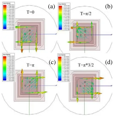
Figure 11 shows the current density graphs of bottom patch at time T = 0, π/2, π and π∗3/2 from subgraph (a) to subgraph (d). Figure 12 and Figure 13 show the current density graphs of middle and top patches, respectively. The vector of the current density on bottom and middle layer patches is traced in a counterclockwise sense as time increases, so F1 and F2 bands are RHCP. And F3 band will
(a) (b)
Figure 14. (a) Simulated AR and (b) measured AR of the designed triple-band antenna.
(a) (b) (c)
Figure 15. (a) Simulated Gain patterns at phi = 0 deg plane. (b) Measured gain patterns at phi = 0 deg plane. (c) Measured gain patterns at phi = 90 deg plane.
be LHCP because vector of the current density on the top layer patch is traced in clockwise sense. Figure 14 shows that the simulated and measured axial ratios change with theta from−180 deg to 180 deg on the phi = 0 deg plane. Both simulated and measured axial ratios of the three resonate bands are less than 3 dB at vertical direction.
Figure 15 shows that the simulated and measured gain patterns change with theta from−180 deg to 180 deg on the phi = 0 deg and phi = 90 deg plane. And the peak gain is more than 4 dBic. The peak gain at F1 band of the antenna is 7.0 dBic, and directivity is 7.2 dBic. So efficiency of the antenna is about 95.6%, which is 95.1% and 95.3% at F2 and F3 bands, respectively.
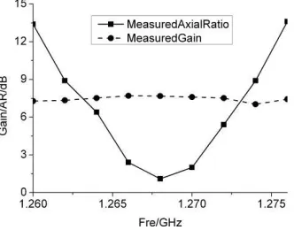
Figure 16 shows that the measured AR and gain pattern of the bottom layer change with frequency at phi = 0 deg, theta = 0 deg plane. The measured circular bandwidth is about 6 MHz, and the gain is more than 6 dBic in F1 band. Circular bandwidths of middle and top layers are both 8 MHz.
4. CONCLUSION
A compact-size triple-band stacked multi-port CP microstrip antenna is proposed in this paper. The measured results agree well with the simulated ones. S11 of all three bands can cover the system
application, and axial ratio at center band is smaller than 3 dB at vertical direction in both simulated and measured results. Peak gain of three center bands is more than 4 dBic.
ACKNOWLEDGMENT
This work was supported in part by the National Natural Science Foundation of China (Nos. 61271416 and 61301093), Fundamental Research Funds for the Central Universities (No. 3102014KYJD027), and NPU Foundation for Fundamental Research (No. JCY20130132).
REFERENCES
1. Siakavara, K., “A compact fractal microstrip antenna for GPS and terrestrial radio services,” International Journal of Electronics, Vol. 94, 277–283, 2007.
2. Eissfeller, B., G. Ameres, V. Kropp, and D. Sanroma, “Performance of GPS, GLONASS and Galileo,” 185–199, 2007.
3. Haneishi, M. and Y. Suzuki, “Circular polarization and bandwidth,” Handbook of Microstrip Antennas, J. R. James, P. S. Hall, Peter Peregrinus, London, 1989.
4. Ferrero, F., C. Luxey, G. Jacquemod, and R. Staraj, “Dual band circular polarized microstrip antenna for satellite applications,” IEEE Antennas and Wireless Prop. Lett., Vol. 4, 13–15, 2005. 5. Yang, S. S., K. F. Lee, A. A. Kishk, and K. M. Luk, “Design and study of wideband single feed
circularly polarized microstrip antennas,” Progress In Electromagnetics Research, Vol. 80, 45–61, 2008.
6. Sharma, P. C. and K. C. Gupta, “Analysis and optimized design of single feed circularly polarized microstrip antennas,” IEEE Trans. Antennas Propag., Vol. 31, 949–955, 1983.
7. Elhefnawy, M., W. Ismail, and J. S. Mandeep, “Circular polarisation diversity with small size microstrip antenna,”International Journal of Electronics, Vol. 96, 1197–1205, 2009.
8. Yang, S. L. S., R. Chair, A. A. Kishk, K. F. Lee, and K. M. Luk, “Study on sequential feeding networks for sub arrays of circularly polarized elliptical dielectric resonator antenna,”IEEE Trans. Antennas Propag., Vol. 55, 321–333, 2007.
9. El Hajj, W., F. Gall´ee, and C. Person, “Tri-access tri-band reconfigurable stacked patch wire-plate antenna,” 6th European Conference on Antennas and Propagation, 3574–3578, 2012.
11. Heidari, A. A., M. Heyrani, and M. Nakhkash, “A dual-band circularly polarized stub loaded microstrip patch antenna for GPS applications,” Progress In Electromagnetics Research, Vol. 92, 195–208, 2009.
12. Vasistha, P. and B. R. Vishvakarma, “Some studies on two-layer electromagnetically coupled microstrip antenna with dielectric cover,” International Journal of Electronics, Vol. 86, 991–998, 1999.
13. Alkanhal, M. A. S., “Composite compact triple-band microstrip antennas,” Progress In Electromagnetics Research, Vol. 93, 221–236, 2009.
14. Ahdi Rezaeieh, S. and M. Kartal, “A new triple band circularly polarized square slot antenna design with crooked T and F-shape strips for wireless applications,” Progress In Electromagnetics Research, Vol. 121, 1–18, 2011.
15. Binoy, G. S., C. K. Aanandan, P. Mohanan, and K. Vasudevan, “Dual-frequency dual-polarized slot-coupled compact microstrip antenna for communication systems,” International Journal of Electronics, Vol. 89, 191–195, 2002.