AN APPROACH TO EQUIVALENT CIRCUIT MODELING OF RECTANGULAR MICROSTRIP ANTENNAS
M. Ansarizadeh and A. Ghorbani
Department of Electrical Engineering Amirkabir University of Technology 424 Hafez Ave., Tehran, Iran
R. A. Abd-Alhameed
Mobile and Satellite Communication Centre University of Bradford
Bradford BD7 1DP, U.K.
Abstract—Computation of the broadband matching potential of a microstrip antenna requires the wideband lumped equivalent circuit of the antenna. The general topology of the equivalent circuit of rectangular microstrip patch antennas has been used to model the feed-point impedance of microstrip antennas over a wide frequency band and equivalent circuit parameters are determined using optimization techniques. The proposed procedure overcomes the problems of physical realizability of the equivalent circuit and estimation of the starting values of the optimization. Applying this technique, wideband lumped equivalent circuits of a rectangular and E-shaped microstrip antenna have been computed which are in good agreement with measurement data from 0.1 to 6 GHz.
1. INTRODUCTION
applying the Fano or Youla gain-bandwidth theory to the lumped equivalent circuit of the antenna [4–6]. Although impedance matching networks can enhance the impedance bandwidth of a microstrip antenna [7–9], the resulting bandwidth is always smaller than the maximum theoretical bandwidth which is given by the Fano or Youla theory [5, 6].
The narrowband equivalent circuit of a rectangular microstrip patch antenna (RMPA) has been related to the physical dimensions of the antenna [10]. Kajfez proposed a systematic approach to calculate the equivalent circuit of double resonant microstrip antennas [11]. Later, Kim devised a procedure to calculate the wideband equivalent circuit of broadband antennas [12]. However, the singular value decomposition technique utilized in [12] has failed to converge to physically realizable circuits in case of rectangular and wideband E-shaped microstrip antennas. In this paper, the topology of the equivalent circuit is fixed and thus, this issue has been resolved in case of rectangular and wideband E-shaped microstrip antennas.
In general, wideband equivalent circuits of microstrip antennas are determined by using optimization techniques [11–14]. In case of the equivalent circuit that models double resonant microstrip antennas, Kajfez devised a systematic approach to calculate the starting values of the involving optimization [11]. On one hand, no systematic method has been provided to estimate the starting values of the optimization process in case of wideband equivalent circuits that model antennas in more than two radiation resonances, on the other hand, as the number of resonances that equivalent circuits of antennas should model increases, the number of the parameters of the equivalent circuit increases too and thus, the convergence and computation cost of the involving optimization technique becomes critically sensitive to the starting values of the optimization such that optimization methods will not converge unless starting values are “close enough” to the final parameters of the equivalent circuit. The proposed method overcomes this problem, as well.
2. EQUIVALENT CIRCUIT TOPOLOGY
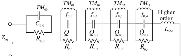
The general topology of the wideband lumped equivalent circuit of RMPAs is determined as shown in Fig. 1 by applying the modified mode expansion technique to the advanced cavity model of RMPAs [15]. This topology has been used in case of the E-shaped microstrip antenna reported in [16] and its slot-less form which are depicted in Fig. 2. The generated modes in the wideband E-shaped antenna [16– 18] are basically perturbed versions of the modes that are excited in conventional RMPAs and the radiating modes are modeled as the series connection of parallel resonant sections [15]. The slots on the patch contribute to perturbations in radiating modes which can expand the antenna bandwidth or generate dual-band functionality [16–23].
0,1
R
eqZ
0, 0
C
0, 0
R
00
TM
0,1
Q
0,1
f
01
TM
0, 2
R
0, 2
Q
0, 2
f
10
TM
0, 3
R
0, 3
Q
0, 3
f
02
TM
0, 4
R
0, 4
Q
0, 4
f
11
TM
L Higher
order
Figure 1. General topology of the equivalent circuit of rectangular microstrip antennas.
3. CALCULATION OF CIRCUIT PARAMETERS
The geometries of the wideband E-shaped microstrip antenna reported in [16] and its slot-less form are depicted in Fig. 2. Physical dimensions of these antennas are illustrated in Fig. 2 and the values of dimensions are given by:
(L, W, H)=(70,45,10),(Xf, Yf) = (35,7),(Ls, Ws, Ps) = (35,4,9) (1)
(L, W, H)=(70,45,10),(Xf, Yf) = (35,7) (2)
where dimensions are in millimeter.
Top View Side View Top View Side View
(a) (b)
Figure 2. Geometries of a rectangular and the E-shaped microstrip antenna reported in [16].
0 2 4 6
0 50 100 150 200
Frequency, GHz
Ohm
Re[Zm] Im[Zm]
0 2 4 6
0 50 100 150 200
Frequency, GHz
Ohm
Re[Zm] Im[Zm]
(a) (b)
Figure 3. Measured values of the feed-point impedance of the rectangular and E-shaped microstrip antennas depicted in Fig. 2.
The parameters of the equivalent circuit shown Fig. 1 are determined by the nonlinear curve-fitting optimization technique such that the resulting circuit parameters minimize the error function defined by:
∆zrms≡ 1
Z0
1
N
N
k=1
Re [Zm(fk)−Zeq(fk)]2+Im[Zm(fk)−Zeq(fk)]2
where Z0 is the reference impedance and is set to 50 Ω, Zm and
Zeq are respectively the measured and equivalent circuit values of the feed-point impedance of the antenna, fk is the kth frequency of measurement andN is the number of measurement samples.
Referring to Fig. 1, R0,0 is the conduction loss of the substrate
material for theT M00mode which is negligible for low-loss substrates,
such as air. With this assumption, we arrive at the general form of the input impedance of the equivalent circuit of microstrip antennas:
Zeq(f) =j2πf L∞+
1
j2πf C0,0
+ M
i=1
R0, i
1 +jQ0, i
f f0, i −
f0, i
f
(4)
where L∞ and C0,0 specify the asymptotic behavior of the
feed-point impedance of the antenna at the higher and lower edges of the frequency band of modeling, respectively;M is the number of radiation resonances in the frequency band of interest; And f0, i, Q0, i and R0, i are the resonant frequency, Q-factor and radiation resistance of theith radiating mode, respectively.
The input impedance of the antenna at sufficiently low frequencies can be approximated by:
lim
f→0Zeq(f) = limf→0
1
j2πf C0,0
+jf
2πL∞+ M
i=1 R0, i
Q0, if0, i
= 1
j2πf C0,0
(5)
By computing the first order derivate of (5) with respect to frequency, it’s found that C0,0 is estimated by:
C0,0 ≈ lim
f→0
1
2πf2∂I m [Zm(f)] ∂f
≈ 6
πf32∆fI m [Zm(f1)−8Zm(f2) + 8Zm(f4)−Zm(f5)]
(6)
where ∆f = f2 −f1 is the sampling frequency interval. The right
hand side of (6) should be evaluated at frequencies in which the effect of C0,0 constitutes the dominant term in (4). Similarly, at sufficiently
high frequencies, the effect ofL∞constitutes the dominant term of the input impedance of the antenna and (4) can be approximated by (7) and thus,L∞ can be estimated by the slope of the input reactance of the antenna as given by (8).
lim
f→∞Zeq(f) =j2πL∞f + 1
jf
1 2πC0,0
+ M
i=1
R0, if0, i
Q0, i
L∞≈ lim f→∞
∂I m [Zm(f)] 2π∂f
≈I m [Zm(fN−4)−8Zm(fN−3)+8Zm(fN−1)−Zm(fN)]
24π∆f (8)
Practically, (8) is evaluated at frequencies that are higher than all resonant frequencies of the parallel resonant sections such that the slope of the real part of the input impedance of the antenna versus frequency as shown in Fig. 3, becomes negligible.
In order to estimatef0, i,Q0, i and R0, i for each parallel resonant section in Fig. 1, we assume that these parameters are such that at
f = f0,i, the contribution of the remaining parallel sections in (4)
is negligible so that the radiation resistance and Q-factor of the ith radiating mode can be approximated by (9) and (10), respectively.
R0, i ≈ Re [Zm(f)]|f=f0, i (9)
Q0, i ≈ −
f0, i 2R0, i ×
Im
∂Zm(f)
∂f
f=f0, i
(10)
The resonant frequencies of the parallel sections in Fig. 1 are considered to be every frequencyfk, at which the following equations are satisfied:
∂Re [Zm(f)]
∂f
f=fk−1
× ∂Re [Zm(f)]
∂f
f=fk+1
< 0 (11)
∂I m [Zm(f)]
∂f
f=fk
< 0 (12)
∂Re [Zm(f)]
∂f
f=fk−1
< 0 (13)
where k = 3,4, . . . , N −2 because the first order derivates of the smoothed impedance data are evaluated by the numerical central difference which is chosen to be of O(∆f)4.
Before calculating the derivatives of measurement data with respect to frequency in (10)–(13), it’s necessary to note that measurement data are often corrupted by noise from various sources and thus, it is necessary to smooth the real and imaginary components of the measured input impedance prior to any differentiation. In this paper, a moving average method is applied to measurement data in MATLAB to minimize effects of noise while estimating the starting values of the optimization.
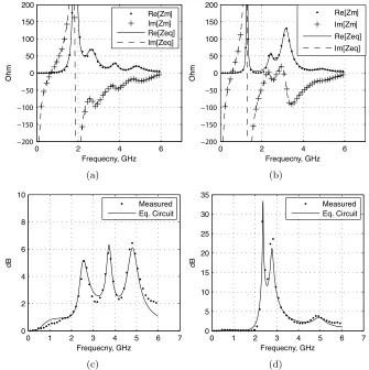
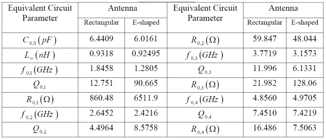
values of the parameters of the equivalent circuits are obtained using (6) and (8)–(13). The exact values of these parameters are calculated by altering the starting values through the non-linear curve-flitting optimization such that the error function defined by (3) is minimized. The optimization process converged to circuit parameters that are given in Table 1 and correspond to ∆zrms = −19.66 dB and ∆zrms = −7.73 dB for the rectangular and E-shaped microstrip antenna, respectively. The input impedance and return loss of the resulting equivalent circuits are compared with measurement data in Fig. 4.
0 2 4 6
0 50 100 150 200
Frequecny, GHz
Ohm
Re[Zm] Im[Zm] Re[Zeq] Im[Zeq]
0 2 4 6
0 50 100 150 200
Frequecny, GHz
Ohm
Re[Zm] Im[Zm] Re[Zeq] Im[Zeq]
(a) (b)
0 1 2 3 4 5 6 7 0
2 4 6 8 10
Frequecny, GHz
dB
Measured Eq. Circuit
0 1 2 3 4 5 6 7 0
5 10 15 20 25 30 35
Frequecny, GHz
dB
Measured Eq. Circuit
(c) (d)
Table 1. The parameters of the equivalent circuits of the rectangular and E-shaped microstrip antennas depicted in Fig. 2.
Table 1 reveals thatC0,0 andL∞ are relatively independent from
the parallel slots on the patch. Moreover, incorporation of parallel slots reduces the resonant frequencies of the T M01, T M10 and T M02
modes that are excited in the structure of RMPAs.
Figure 4 also shows good agreement between the measured and equivalent circuit values of the input impedance and return loss of the rectangular and E-shaped microstrip antennas depicted in Fig. 2, in a frequency band that starts from zero and includes up to four radiating modes.
4. CONCLUSIONS
REFERENCES
1. Ghorbani, A. and R. A. Abd-Alhameed, “An approach for calculating the limiting bandwidth — Reflection coefficient product for microstrip patch antennas,” IEEE Trans. Antennas Propag., Vol. 54, No. 4, 1328–1331, Apr. 2006.
2. Ghorbani, A. and M. A. Ansarizadeh, “The bode-fano integrals as an objective measure of antenna bandwidth reflection coefficient product limit,”2006 International RF and Microwave Conference Proceedings, Putrajaya, Malaysia, Sept. 12–14, 2006.
3. Zhu, L. and Y. Qi, “A novel approach to evaluating the gain-bandwidth potential of antennas,” Antennas and Propagation SocietyInternational Symposium, AP-S. Digest, Vol. 3, 2058– 2061, Jul. 1996.
4. Gustafsson, M. and S. Nordebo, “Bandwidth, Q factor, and resonance models of antennas,” Progress In Electromagnetics Research, PIER 62, 1–20, 2006.
5. Fano, R. M., “Theoretical limitations on the broadband matching of arbitrary impedances,”J. Franklin Institution, Vol. 249, 57–83, 139–155, Jan./Feb. 1950.
6. Youla, D. C., “A new theory of broadband matching,” IEEE Trans. on Circuit Theory, Vol. 11, 30–50, Mar. 1964.
7. Khalaj-Amirhosseini, M., “Wideband or multiband complex impedance matching using microstrip nonuniform transmission lines,” Progress In Electromagnetics Research, PIER 66, 15–25, 2006.
8. Liu, S.-F., X.-W. Shi, and S.-D. Liu, “Study on the impedance-matching technique for high-temperature superconducting mi-crostrip antennas,” Progress In Electromagnetics Research, PIER 77, 281–284, 2007.
9. Abdelaziz, A. A., “Bandwidth enhancement of microstrip antenna,”Progress In Electromagnetics Research, PIER 63, 311– 317, 2006.
10. Abboud, F., “Simple model for the input impedance of coax-fed rectangular microstrip patch antenna for CAD,”IEE Proceedings, Vol. 135, Pt. H, No. 5, Oct. 1988.
11. Kajfez, D., “Deembedding of lossy foster networks,”IEEE Trans. Antennas Propag., Vol. 53, No. 10, 1328–1331, Oct. 2005.
13. Wang, Y., J. Li, and L.-X. Ran, “An equivalent circuit modeling method for ultra-wideband antennas,” Progress In Electromagnetics Research, PIER 82, 433–445, 2008.
14. Yarman, B. S., A. Kilinc, and A. Aksen, “Immitance data modelling via linear interpolation techniques: A classical circuit theory approach,” International Journal of Circuit Theoryand Applications, Vol. 32, 537–563, 2004.
15. Richards, W., “An improved theory for microstrip patches,”IEE Proc., Vol. 132, Pt. H, 93–98, 1985.
16. Yang, F., X.-Z. Zhang, and Y. R. Samii, “Wideband E-shaped patch antennas for wireless communications,”IEEE Trans. Antennas Propagat., Vol. 49, No. 7, Jul. 2001.
17. Ang, B.-K. and B.-K. Chung, “A wideband E-shaped microstrip patch antenna for 5–6 GHz wireless communications,”Progress In Electromagnetics Research, PIER 75, 397–407, 2007.
18. Ansari, J. A. and R. B. Ram, “E-shaped patch symmetrically loaded with tunnel diodes for frequency agile/broadband operation,”Progress In Electromagnetics Research B, Vol. 1, 29– 42, 2008.
19. Jolani, F., A. M. Dadgarpour, and H. R. Hassani, “Compact M-slot folded patch antenna for WLAN,”Progress In Electromagnet-ics Research Letters, Vol. 3, 35–42, 2008.
20. Sadat, S., M. Fardis, F. G. Kharakhili, and G. Dadashzadeh, “A compact microstrip square-ring slot antenna for UWB applications,” Progress In Electromagnetics Research, PIER 67, 173–179, 2007.
21. Khodae, G. F., J. Nourinia, and C. Ghobadi, “A practical miniaturized U-slot patch antenna with enhanced bandwidth,”
Progress In Electromagnetics Research B, Vol. 3, 47–62, 2008. 22. Sadat, S., M. Houshmand, and M. Roshandel, “Design of a
microstrip square-ring slot antenna filled by an H-shape slot for UWB applications,” Progress In Electromagnetics Research, PIER 70, 191–198, 2007.
![Figure 2. Geometries of a rectangular and the E-shaped microstripantenna reported in [16].](https://thumb-us.123doks.com/thumbv2/123dok_us/1904828.1249497/4.612.100.428.312.475/figure-geometries-rectangular-e-shaped-microstripantenna-reported.webp)