Mitigation of Harmonics in 3-phase 3-wire System by using
Fuzzy Logic Controlled Shunt Active Filter
Siva Santosh Kumar Dakamari & T.Ramesh Babu
M-tech Student Scholar Dept of Electrical & Electronics Engg, Sanketika Vidya Parishad Engg. College, P.M.Palem, Visakhapatnam (Dt); A.P, India.
E-Mail: [email protected]
M.Tech Assistant Professor Dept of Electrical & Electronics Engg, Sanketika Vidya Parishad Engg. College,
P.M.Palem, Visakhapatnam (Dt); A.P, India. E-Mail:[email protected]
.
Abstract-Most of the pollution issues created in power systems are due to the non-linear characteristics and fast switching of power electronic equipment. Due to this harmonics are produced and reactive power compensation is required, so that system efficiency is less and power factor is poor. Active power filters have been developed over the years to solve these problems to improve power quality. Among which shunt active power filter is used to eliminate and load current harmonics and reactive power compensation. The advantage of fuzzy control is that it provides linguistic values such as low, medium, high that are useful in case where the probability of the event to occur is needed. Advancement in semiconductor devices has fuelled an increase in the use of non-linear loads which are the main causes of harmonic distortion in three-phase, three-wire distribution systems. Mitigation of harmonics in three-phase, three-wire electrical power distribution systems that supply balanced and unbalanced non-linear loads was therefore conducted. In order to protect the supply system from current harmonics, we have to use the active power filters. Simulink model is developed for three phase three wire system under balanced source condition and three phase three wire system for unbalanced source condition. The performance of both balanced source and unbalanced source is done using Fuzzy Logic Controller and PI controller and their Simulink results is compared. Simulation results obtained shows that the performance of fuzzy controller is found to be better than PI controller.
Keywords: Shunt active power filter, P-Q theory, Voltage source inverter, Current source inverter, Harmonics compensation.
I. INTRODUCTION
The non-linear characteristics and fast switching of power electronic equipment is the main source of power system problems. The more the use of special electronic components in the equipment used in the generation and distribution creates new phenomenon which makes interest in the area of power quality. But this newer phenomenon reduces the quality of power [1-2]. Electric Power quality is the measure of consumer satisfaction in using the equipment of serves the need. Power quality issues are becoming stronger due to the usage of the sensitive equipment that will in turn continuously pollute the system more and more. Both power suppliers and end users are concerned about this
power quality problem and compensation techniques [3-4]. The power electronic equipment includes adjustable speed motor drives, DC motor drives, battery chargers, electronic ballasts all causes a rise in PQ related problems. These controllers are used in HV dc systems and renewable electrical power generation [5]. These are the non-linear loads (NLL) which draws current not linearly with voltage are the prime source of harmonic distortion in a distribution system [6]. The distorted current contains multiples of sine waves at multiples of fundamental frequency. These are called current harmonics. These current harmonics are injected into distribution system at the point of common coupling (PCC). Hence harmonic voltage is produced which combines the pure source voltage cause distortion in source voltage [7]. This is fed to the electrical equipment connected to the same bus. It is a form of electrical pollution which declines the quality of electrical supply. In a three phase systems, they could cause unbalance and draw excessive neutral current. They even disturb the adjacent consumers connected to the bus and cause interference in nearby communication. Harmonic distortion can be reduced by two ways. One is the conventional method of filtering using the reactive storage components like R, L, C components to mitigate harmonics. Basically there are two types of passive filter. Shunt passive which uses L and C in parallel to the grid and the series passive filter which uses L and C in series to the supply [8-9].
conditions and Simulink models also has been developed for the same for different parameters and operating conditions [12].
II. Classification of Active Power Filters
Mainly there are three types of active power filter: Based on the converter type
1. VSI Inverter 2. CSI Inverter Based on topology
1. Active Shunt Filter 2. Active series Filter Hybrid filter
Based on supply system 1. 1-Phase-2 wire system 2. 3-Phase -3 wire system 3. 3-Phase-4 wire system
Fig.1 (i) CSC and (ii) VSC type shunt active power filter.
The main difference between these two topologies is energy storage element connected at DC link side. In fig.1(i) CSC type shunt active power filter, the converter is formed by six controllable switches in series with diodes and LfCf filter is connected in
between the PWM converter and supply mains and it is used to suppress ripples in output of the converter. In fig.1(ii) VSC type shunt active power filter, the converter is formed by six controllable switches in shunt with diodes and Lf filter is connected in between the PWM converter and supply mains and it is used to suppress ripples in output of the converter [6]-[8]. This project presents the VSC type shunt active power filter. Basically the shunt active power filter is connected at point of common coupling, the basic principle of the active power filter is injected the reference harmonic currents in phase opposition to current harmonics produced by the non-linear loads. Due to that cancellation of current harmonics, we will get sinusoidal waveform at point of common coupling.
III.3-PHASE, 3-WIRE SAPF TOPOLOGY
A. Instantaneous real active and reactive power method:
The basic block diagram of 3-phase, 3-wire shunt active power filter is shown in Fig.2 [11]. Here the source is connected to the non-linear load, these non-linear loads always generates current harmonics. Due to these current harmonics, distorted waveform is appeared at point of common coupling. For getting sinusoidal waveform at point of common coupling we have to connect the shunt active power filter [7], [8]. These shunt active power filter consists of Lf filter and voltage source converter which is having six controllable switches in parallel with the diodes. Here the shunt active power filter takes the harmonic currents information from the nonlinear load, it gives the information to the PWM circuit, these PWM circuit generates the gating signals to the voltage source inverter. In the voltage source inverter, the switches are operating according to the generation of gating signals [9], [10].
Fig.2The basic block diagram of three phase three wire shunt active power filter.
The output of the voltage source inverter is passing through the Lf filter. These Lf filter is used to add the reference signals in phase opposition to the actual current harmonics generated by the non-linear load. These shunt active power filter can be operated with the help of real and reactive power control strategy.
Fig.3Active filter controller block diagram.
diagram as shown in Fig.3. Former days the calculations of power flow were consequential from the average powers or root mean square values of voltages and currents. Akagi. H, proposed one method for calculating reference compensation currents called the instantaneous P-Q method (i.e., instantaneous real active and reactive power theory) [12]. These reference compensation currents are required to inject into the network, where nonlinear loads are connected. This P-Q theory is based on time domain analysis. By using of this P-Q theory, information of both load line currents and source voltages converters α-β-0coordinates with the help of instantaneous power calculation [11]. So the P-Q theory has been used the transformation called Clarke transformation. It is used to plot the three phase supply/source instantaneous voltages and output/load line currents into α-β-0coordinates. The transformation matrices C and C⎯¹ for transformation of Clarke and back transformation are given respectively in equations.
( 𝑉𝑖𝑛0 𝑉𝑖𝑛𝛼 𝑉𝑖𝑛𝛽 ) = 𝐶 ( 𝑉𝑎 𝑉𝑏 𝑉𝑐 ) (1) ( 𝑉𝑖𝑛0 𝑉𝑖𝑛𝛼 𝑉𝑖𝑛𝛽
) =√2
3 (
1 √2⁄ 1 √2⁄ 1 √2⁄
1 −1 2⁄ −1 2⁄
0 √3 2⁄ −√3 2⁄
) ( 𝑉𝑎 𝑉𝑏 𝑉𝑐 ) (2) ( 𝑉𝑎 𝑉𝑏 𝑉𝑐
) = 𝐶−1(
𝑉𝑖𝑛0 𝑉𝑖𝑛𝛼 𝑉𝑖𝑛𝛽 ) (3) ( 𝑉𝑎 𝑉𝑏 𝑉𝑐
) =√2
3 (
1 √2⁄ 1 0
1 √2⁄ −1 2⁄ √3 2⁄ 1 √2⁄ −1 2⁄ −√3 2⁄
) ( 𝑉𝑖𝑛0 𝑉𝑖𝑛𝛼 𝑉𝑖𝑛𝛽 ) (4) The equations (1), (2), (3), and (4) are shown above. These are given as voltage wave but they are also applicable for current waves. Here “0” represents the zero sequence component of voltage wave/current wave. In three phase three wire system, zero sequence components can’t flow. So that zero sequence components, from above equations (1), (2), (3) and (4) are eliminated and the α-β axes transforming into three phase balanced -linear system.
(𝑄𝑃𝑟 𝑟) = ( 𝑉𝑖𝑛𝛼 𝑉𝑖𝑛𝛽 𝑉𝑖𝑛𝛽 −𝑉𝑖𝑛𝛼) ( 𝐼𝑜𝑝𝛼 𝐼𝑜𝑝𝛽) (5) Rearranging equation (5)
(𝐼𝐼𝑜𝑝𝛼
𝑜𝑝𝛽) =
1 𝑉𝑖𝑛𝛼2 + 𝑉
𝑖𝑛𝛽2 (𝑉𝑉𝑖𝑛𝛼 𝑉𝑖𝑛𝛽 𝑖𝑛𝛽 −𝑉𝑖𝑛𝛼) ( 𝑃𝑟 𝑄𝑟) (6) 𝑃𝑟= 𝑃𝑟+ 𝑃̅𝑟 (7) 𝑄𝑟= 𝑄𝑟+ 𝑄̅𝑟 (8) From equations (7) and (8), Pr be the instantaneous real power is the sum of average and oscillating real powers and Qr be the instantaneous imaginary power is the sum
of average and oscillating reactive powers. For linear load, Pr and Qr are having only DC/constant/average
values. However if load may be bridge rectifier as a non-linear load, the current waveform should enclose not only the 50 Hz/fundamental frequency component but also the multiple of 50 Hz/fundamental frequency components. Then the instantaneous Pr and Qr should include constant dc or average component and fluctuating or oscillating component as decomposing in equations (7) and (8) The average component of real Pr and reactive Qr can’t to exist as reference powers so that oscillating components of real Pr and imaginary power Qr must have to chosen as reference powers, if the shunt active power filter is deliberate for compensation current harmonics or circulating currents. From the active power filter controller block diagram, the low pass filter (LPF) is used to absorb the average/constant dc component/element and selecting the fluctuating/oscillating component/elements in equations (7) and (8) and back transformation is used to get the desire compensation reference currents (𝑖𝑐𝑎∗ ,𝑖𝑐𝑏∗ ,𝑖𝑐𝑐∗ ) in the form of a-b-c coordinates in Fig.4.
Fig.4. Calculation of current reference based on P-Q theory.
B. Importance of DC capacitor
The voltage of DC capacitor may be restricted by a DC voltage regulator. A low –pass filter is used it anesthetized to the fundamental (50 Hz) voltage frequency oscillations. The clean voltage variation occurs, according to the subsequent equations regulation of voltage (∈𝑟) is given as,
∈𝑟= −1; 𝑉𝑑𝑐< −0.05𝑉𝑑𝑐 𝑟𝑒𝑓
(9)
∈𝑟=
𝑉𝑑𝑐
−0.05𝑉𝑑𝑐 𝑟𝑒𝑓
; −0.05𝑉𝑑𝑐 ≤ 𝑉𝑑𝑐≤ −0.05𝑉𝑑𝑐 𝑟𝑒𝑓
(10)
∈𝑟= 1; 𝑉𝑑𝑐> 0.05𝑉𝑑𝑐 𝑟𝑒𝑓
(11) If Vdc< Vref_dc; the pulse width Modulated inverter
should be collect the energy from ac main to the dc capacitor. If Vdc>Vref_dc; the pulse width modulated
inverter should be carrying the energy from dc capacitor to ac main.
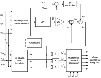
Fig.5. generating gate signals for shunt active filter.
The above Fig.5 shows that PWM control circuit of shunt active power filter based on generation of current references contains active power measurement, PI – controller, low pass filter, reference current generator and hysteresis (Iopa, Iopb, Iopc), the voltages at point of
coupling (Vina,Vinb,Vinc) and DC link voltage Vdc are
sensed signals, and these are used as feedback signals. The bigger current references are getting as a result of modifiable the dc link voltage. The error signal is obtained from comparing the actual dc link voltage with Vref_dc (reference DC voltage). The DC bus error voltage is given as
𝑉
𝑑𝑐 𝑒𝑟𝑟= 𝑉
𝑑𝑐~𝑉
𝑑𝑐 𝑟𝑒𝑓(12) Here the PI – controller is used for DC bus control. So When the error signal is flowing by the way of PI controller, its controls the DC bus current signal, which will give the greater value of supply current included with the controller and is thus made accessible at zero crossing only. The output result of the PI controller is greater value of supply current that is the classified into of two elements/components.
Those are
(1). Fundamental element/component of active output/load current of SHAF and
(2). Loss element/component of active output/load current of SHAF.
The greater value of the current is multiply with sinusoidal waveform in phase with input/source voltage to get compensating reference current waves. These compensating reference wave currents compared with the help of actual current waves in the hysteresis band, which will give the slipup signal to the modulation technique [5], [6]. Then this error signal will choose the action of voltage source inverter switches, these are generates the reference harmonic currents injected with the help of voltage source inverter.
V.FUZZY CONTROLLER
Figure.6 shows the internal structure of the control circuit. The control scheme consists of Fuzzy controller,
limiter, and three phase sine wave generator for reference current generation and generation of switching signals. The peak value of reference currents is estimated by regulating the DC link voltage. The actual capacitor voltage is compared with a set reference value. The error signal is then processed through a Fuzzy controller, which contributes to zero steady error in tracking the reference current signal. A fuzzy controller converts a linguistic control strategy into an automatic control strategy, and fuzzy rules are constructed by expert experience or knowledge database. Firstly, input voltage Vdc and the input
reference voltage Vdc-ref have been placed of the angular
velocity to be the input variables of the fuzzy logic controller. Then the output variable of the fuzzy logic controller is presented by the control Current Imax. To
convert these numerical variables into linguistic variables, the following seven fuzzy levels or sets are chosen as: NB (negative big), NM (negative medium), NS (negative small), ZE (zero), PS (positive small), PM (positive medium), and PB (positive big) as shown in Figure 7.
The fuzzy controller is characterized as follows: 1) Seven fuzzy sets for each input and output; 2) Fuzzification using continuous universe of dis-course;
3) Implication using Mamdani's ‘min’ operator; 4) De-fuzzification using the ‘centroid’ method.
Fig.7. (a) Input Vdc normalized membership function; (b) Input Vdc-ref Normalized Membership Function; (c) Output Imax Normalized
Membership Function.
Fuzzification: the process of converting a numerical variable (real number) convert to a linguistic variable (fuzzy number) is called fuzzification.
De-fuzzification: the rules of FLC generate required output in a linguistic variable (Fuzzy Number), according to real world requirements, linguistic variables have to be transformed to crisp output (Real number).
Database: the Database stores the definition of the membership Function required by fuzzifier and defuzzifier.
Rule Base: the elements of this rule base table are determined based on the theory that in the transient state, large errors need coarse control, which requires coarse in-put/output variables; in the steady state, small errors need fine control, which requires fine input/output variables. Based on this the elements of the rule table are obtained as shown in Table, with ‘Vdc’ and
‘Vdc-ref’ as inputs.
Table Rules for Fuzzy System
VI. MATLAB/SIMULINK RESULTS Case 1: 3-phase 3-wirebalanced source
Fig.8. Simulink circuit for balanced 3-phase 3-wire system.
Fig.10.FFT Analysis for Source Current.
Case 2: 3-phase 3-wire unbalanced source
Fig.11.Simulation results for unbalanced system.
Fig.12. FFT analysis source current Case 3: 3-phase 3-wire non sinusoidal source
Fig.13.Simulation results for non sinusoidal source.
Fig.14.FFT analysis for source current.
Case 4: balanced three phase with dynamic load changes.
Fig.16.FFT analysis for source current.
Case 5: unbalanced three phase with dynamic load changes.
Fig.17. Simulation results for unbalanced three phase with load changes.
Fig.18.FFT analysis for source current.
Case 6: 3-phase 3-wire non-sinusoidal source with Dynamic Load change.
Fig.19. Simulation results for non-sinusoidal source with dynamic load change.
Fig.21. Matlab/Simulink Model of Proposed 3-phase 3-Leg SHAF system With Fuzzy Logic Control.
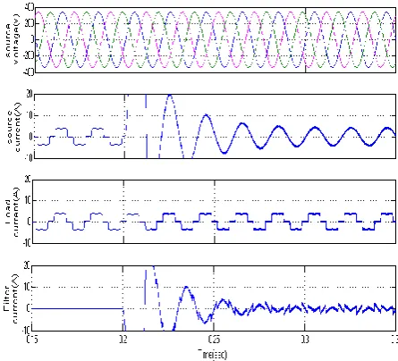
Fig.22. Simulation results for SHAF with fuzzy logic Controller of unbalanced with Dynamic load (a) Source Voltage. (b) Source
Current (c) Load current (d) Filter current
Fig.23. FFT Analysis for Source Current.
VIII.CONCLUSION
In this paper when the load may be balanced/unbalanced, linear/nonlinear, the source must be sinusoidal. Because of this we can proposed this shunt active filter with PQ theory done in various types of conditions, those are balanced, unbalanced and non-sinusoidal conditions under the PI-controller by the using of simulink/matlab software. Both PI controllers based and fuzzy logic controller based Shunt active power filter are implemented for harmonic and reactive power compensation of the non-linear load. A model has been developed in MATLAB SIMULINK and simulated to verify the results. The performance of both the controllers has been studied and compared. The fuzzy controller based shunt active power filter has a comparable performance to the PI controller in steady state except that settling time is very less in case of fuzzy controller. The proposed controller based shunt active power filter performs perfectly for mitigate the harmonics and FLC is better than other controllers.
REFERENCES
[1] H. Akagi “New trends in active filters for powerconditioning,”IEEE Trans. Ind. Appl.,Vol. 32, No. 6, pp. 1312-1322, Nov./Dec.1996.
[2] F. Z. Peng, G. W. Ott Jr., D. J. Adams, “Harmonic and reactive power compensation based on the generalized instantaneous reactive power theory for three-phase four-wire systems” IEEE Trans. Power Electron.,Vol. 13, No. 5, Nov. 1998.
[3] Fang Zheng Peng and Akagi, (1990), “A NewApproach to harmonic Compensation in PowerSystems A combined System of Shunt Passive andSeries Active Filters”, IEEE Transactions onIndustrial Applications, Vol. 26, pp-6-11.
[4] IEEE Std. 519-1992, “IEEE Recommended Practices and Recquirements for Harmonic Control in Electric Power Systems”. [5] H. Akagi, Y. Kanazawa, A. Nabae,; “Generalize theory of the Instantaneous Reactive Power inThree-Phase Circuits”, IPEC'83 - Int. Power Electronics Conf.,Tokyo, Japan,1983, pp.: 1375 1386. [6] H..R.silva, j.s.martins J.l. Afonso; “Active filters for power quality improvement” IEEE power Tech’2001, Porto,Portugal [18]10-13 sept.2001.
[7] A.nab, H. akagi Y. kanazawa,; “Instantaneous Reactive Power Compensator Comprising Switching Devices without Energy Storage Components”, IEEE Trans. Industry Applic., vol. 20, May/June 1984. [8] IEEE Stc. 519-1981 “Guide for Harmonic Control and Reactive Power Compensation of Static Power Converter”.
[9] R.m. stephan, M. aredes, E.H.watanabe; “New concepts of Instantaneous Active and Reactive Powers in Electrical Systems with generic loads”,IEEE Trans. Power Delivery,vol l.: 8, no: 2, April 199 pp. 697-703.
[10] Z. peng, G.Ott, and D.J. Adams; “Harmonic and Reactive Power Compensation Based on the Generalized reactive Power Theory for Three Phase Four Wire System”, IEEE Transl. Power Eectronics., vol.:13, no:.5, pp.: 1174-1181, N ov.1998.