ISSN 2348 – 7968
Study of Flow Characteristics of Contracted Sharp Crested
Rectangular Weir
Rahul Pandey1, Dr.S.K.Mittal2 and Prof. M.K.Choudhary3
1
M.Tech Student, Department of Civil Engineering, MANIT Bhopal (M.P.), India
2Professor in Department of Civil Engineering, MANIT Bhopal (M.P.), India
3
Associate Professor in Department of Civil Engineering, MANIT Bhopal (M.P.), India
ABSTRACT
Sharp crested rectangular weirs are widely used as discharge measuring device in laboratories, industries and irrigation channels. Analysis of water surface profile and measurement of head over the weir crest are the important aspects in discharge analysis. Width of the weir opening (b) and the weir height (P) affect the coefficient of discharge and thereby the discharge also.
In the present work, an experimental study has been carried out in a rectangular channel of dimensions (9.4 m x 0.6 m x 0.6 m) with contracted sharp crested rectangular weir, by varying the weir width (b) and the weir height (P). The experiment has been conducted in a horizontal channel of width (B). For each weir width, readings are taken for four different weir heights (100 mm, 200 mm, 300 mm and 400 mm.). By varying the discharge for every weir plate, the effect of weir width (b) and weir height (P), has been analyzed in the present study. Variation of coefficient of discharge (Cd) has been analyzed in terms of Reynolds Number (Re) by plotting graphs.
A unique relationship has been developed for estimation of a coefficient K (=0.943 Cd) in terms of modified Reynolds number, 〖Re〗^*={(Re/〖10〗^4 ) 〖C_1〗^2.6 } and the discharge obtained by that equation lies in the range of ±5%. A procedure has also been developed for the estimation of discharge (Q), if head (H) over the weir crest and b/B ratio is known.
Key words: Open Channel Flow, Sharp Crested Weir, Reynolds number, Coefficient of Discharge,
1. INTRODUCTION
Measurement of discharge in open channels plays a vital role in the equal distribution of water among the users in field and accordingly charging correct amount from them by metering the flow. The measurement of flow in open channels is generally made by means of weirs or sluice gates. Various methods are available for the determination of discharge in open channel and can be broadly classified into two groups:
(i) Direct determination
(ii) Indirect Determination
The direct determination of discharge includes various methods like area velocity method, dilution techniques, electromagnetic method and ultrasonic method. The indirect determination of discharge includes hydraulic structures like weirs, flumes, gated structure, end depth ratio method and
slope area method.
Weirs are used to measure discharge in open channels by using the principle of rapidly varied flow. They are extensively used in open channels in irrigation canals, laboratories, industries, and also used as dam instrumentation device. Weirs are most commonly used due to their simplicity and ease in construction, durability and accuracy in measurement.
2. WEIR
Weir is a standard device for the measurement of flow in open channel since last two centuries. It is an obstruction in the path of flow that causes the flow to rise behind the weir and then flows over it. By measuring the head of water over the weir the quantity of discharge can be estimated by using well established head-discharge relationship.
If the jet of liquid passing over the weir springs free as it leaves the upstream face, the weir is known as sharp crested weir, while broad crested weirs are those which support the falling nappe over its crest, in the longitudinal direction and critical depth occurs over the weir.
On the basis of shape, the weirs can be classified as the rectangular, triangular, trapezoidal, parabolic, etc. and are given below:
Sharp crested rectangular weir
Broad crested weir
V-notch weir
Labyrinth weir
Compound weir
Minimum energy loss weir
Sutro weir
Amongst the above mentioned weirs, sharp crested rectangular weir, v-notch and broad crested weir are the most common.
3. SHARP CRESTED RECTANGULAR WEIR
Sharp crested rectangular weir is a thin vertical plate provided in an open channel to estimate the discharge. The edge of the sharp crested weir is bevelled on the downstream side to give a minimum contact with the flowing water. The thickness of weir at the crest is about 0.2 times the thickness of the weir plate and overall thickness of plate is taken about 2 mm. In the downstream side the bevelled surfaces should make an angle between 450 to 600.
The rate of flow is determined by measuring the head (H) over the weir crest at a distance sufficiently upstream at least three to four times the head to be used[2].
The pattern of flow over thin plate weir is very complex and cannot be analyzed theoretically alone. This is due to the non hydrostatic pressure distribution, turbulence, and frictional effects, and the approach flow conditions. The effect of viscosity and surface tension also becomes important at low heads. Therefore the analytical relation between Q and H is obtained after some simplifying assumptions and suitably modifying by experimentally determined coefficients (Cd).
4. Contracted Rectangular Weir: When the width of the crest (b) of a rectangular weir is less than the width of the channel (B), then there will be contraction of the nappe in lateral direction also so that the length of the nappe is less than the channel width. Such types of weirs having end contractions are called as contracted weirs.
TYPES OF SHARP CRESTED RECTANGULAR WEIRS
Full width weirs: It is a weir which extends across the full width of the rectangular approach channel (B/b=1.0). In literature this weir is frequently referred to as a rectangular suppressed weir or Rehbock weir. For suppressed rectangular weir, discharge equation can be derived and is given below[22]:
𝑄=23𝐶𝑑�2𝑔𝐵𝐻3/2 (1)
Where, Q is discharge through weir in m3/s, g is acceleration due to gravity in m/s2, B is width of weir in m, H is the head over weir crest in m and Cd is coefficient of discharge. However for contracted weir, B is replaced by b.
Partially contracted weir: It is a weir in which the contraction of weir is not fully developed due to the proximity of the walls and the bottom of the approach channel, is called as partially contracted weir.
Fully contracted weirs: A sharp crested weir which has an approach channel whose bed and walls are sufficiently remote from the weir crest and sides for the channel boundaries to have no significant influence on the contraction of the nappe. For fully contracted rectangular weir discharge is given as [22 pp. 756]:
𝑄=23𝐶𝑑�2𝑔(𝑏 −0.1𝑛𝐻)𝐻3/2 (2)
Where, b is contracted width of the weir and n is number of end contractions and in present case it (n) is taken as 2.0.
5. BRIEF LITERATURE REVIEW
Till now a lot of works have been carried out by various investigators on sharp crested weirs with different shapes. In case of rectangular sharp crested weirs, many experimental and theoretical works have been carried out and these are summarized in brief as follow:
Rehbock [32] in 1929 carried out experimental work with full width sharp crested rectangular weirs. He concluded that
the discharge coefficient Cd depends upon the head over the weir crest (H) and the weir height (P), while neglecting the viscous and surface tension effects. The empirical equation for discharge coefficient (Cd) is given below:
𝐶𝑑= 0.611 + 0.08𝐻𝑃+1000𝐻 (3)
Kandaswamy et al.[23] in 1936 obtained discharge coefficients on the basis of their experimental results. The results of their study was based on three different ranges of H/P, i.e. H/P ≤ 5, 5< H/P <15 and H/P ≥15. They proposed the following equation for discharge coefficient in the range of H/P ≥ 15:
Cd= 1.06�1 +Hp� 1.5
(4)
Kindsvater and Carter [24] in 1957 made extensive study about rectangular sharp crested weirs. They introduced number of equations for discharge coefficient as a function of H/P and b/B ratios. They introduced a parameter Ce (effective discharge coefficient) which is free from the effect of surface tension and viscosity due to the contraction of water at the weir. According to them the discharge equation is given as follows:
Q = Ce23�2gbeHe
3
2 (5)
In equation (2.4), effective discharge coefficient (Ce) is given by:
Ce= 0.602 + 0.075HP11 (For full width weirs)
The effective width (be) is given as:
be= bc+ Kb (6)
And the effective head (He) is:
He= H1+ Kh (7)
Where, Kb and Kh represent the combined effects of the several phenomena attributed to viscosity and surface tension. The value of Kb is recommended as 0.001 m for all the values of b0/B1 and H1/B1. Where b0 and B1 are the weir width and the channel width respectively.
Ranga Raju and Asawa, [31] carried out experimental studies and they in 1977 found that the pattern of flow over a thin plate weir is very complex and cannot be analysed theoretically alone. This is due to the non-hydrostatic pressure variation, turbulence, frictional effects and the approach flow conditions. The effect of surface tension and viscosity become important at low heads. Following this approach, they obtained the following discharge equation for suppressed thin plate rectangular weir
Q = �23�0.611 + 0.075WH
1�b�2gH
3/2�K
1 (8)
Where W1 is the Weber number and K1 is the Correction factor to account for the effects of viscosity and surface tension.
over a rectangular sharp crested weir in the weir range of
(0 <HP< 10) and the sill range of �10≤P
H≤ ∞� can be
related to the weir parameter H/P semi empirically. They proposed following expression for Cd as follows:
Cd=34
⎩ ⎪ ⎨ ⎪ ⎧�1+HP
H P
�
2
(1−Kf)−Kb�YbH�2
β �YbH �−�
H P 1+HP�
⎭ ⎪ ⎬ ⎪ ⎫ 1 2
(9)
Swamee P.K.[39] in 1988 made extensive experimental studies on rectangular sharp crested weir and proposed a full range expression for Cd in terms of B/b and H/P ratios as follows:
Cd =0.611+2.23�B b� −1�
0.7
1+3.8�B b� −1�0.7 +
0.075−0.011�B b� −1�1.46 1+4.8(B� −1b )^1.46
H
P (10)
Aydin et al [2] in 2002 proposed the concept of slit weir (b/B≤0.25) generally used for measuring the low discharges (up to 0.005 m3/s). They found that the coefficient of discharge (Cd) is a function of Reynolds number (Re) and proposed following equation :
Cd= 0.562 +11√Re.354 (11)
But his equation has certain limitations i.e. b≤0.005 m and b/B≤0.25.
Aydın et al. (2006) [3] modified their above equation (11) to increase the working range of slit weirs for small values of H/b ratio. They carried out experiments for b ranging from 0.005 to 0.075 m in a channel of width 0.30 m with different values of P. The experimental data covers the range of 0.28≤H/b≤55.80. They proposed an equation for Cd as follows:
Cd= 0.562 +
10�1−exp�−�2Hb�2��−1
Re0.45 (12) For H/b≥2, a simplified form for Cd is:
Cd = 0.562 +Re100.45 (13)
Ramamurthy et al.[30] in 2007 proposed the multi-slit concept to remove the limitation on the measuring range of slit weir. The idea was to construct a number (n) of slit weirs side by side so that the discharge of any magnitude can be measured with sufficient accuracy of a slit weir by operating only enough number of slits and closing the others. The minimum spacing required between each slit to prevent any interaction was investigated. They concluded that discharge coefficient depends on Reynolds number for smaller values of R. But for large values of Reynolds number inertia forces are high and viscous forces are negligible, which means that Cd does not depend on Reynolds number. They also showed that the multislit weir can be used to measure wide range of discharge rates. They proposed a functional relation for Cd and discharge equation as follows:
Cd= f(nbB ,Hb,HP, R, W, n) (14)
Q =23Cdnb�2gH
3
2 (15)
PRESENT STUDY
A lot of work has been carried out in the field of contracted rectangular sharp crested weir till now, However, further an attempt has been made in the present study to analyze the flow characteristics of contracted rectangular weir.
In the present work, an experimental analysis has been carried out in rectangular open channel for contracted sharp crested weir.
A very wide range of data has been collected in present study by carrying out experiment. Initially, experiments is conducted for constant width (b) and varying weir heights (P) in order to determine a correlation between discharge coefficient (Cd) and H/P ratio. Then keeping weir height as constant, different weir openings are investigated for weir width ranging from 250 mm to 550 mm. Total sixteen weir plates of different dimensions are investigated.
EXPERIMENTAL PROGRAMME
The experiment was carried out in a rectangular open channel present in the Hydraulics Laboratory of MANIT Bhopal. The rectangular channel was 9.45 m long with a cross section of 60cm x 60 cm as shown in the Fig 1. The side walls of the channel were made of plexi-glass with whole unit resting on three points. A gear mechanism was provided with the channel to change the slope by rotating the gear arrangement. However, in the present case, the slope was kept as horizontal. Three perforated steel sieves were welded just after the entrance of water to the channel to achieve a relatively turbulence free flow. Water was supplied through a centrifugal pump (20HP motor) and a Venturimeter of dimension 6”× 3” was connected to measure the actual discharge. A rolling pointer gauge was provided at the top of railing of the open channel to measure the depth of flow at any section of the channel.
First of all, experiment was carried out with a weir plates of particular width (b) and varying weir heights (P). For each weir plate, further discharge was varied about twelve times by adjusting the inlet valve opening. Then the experiment was repeated with other widths and heights of weir plates. The measurement were taken in terms of head over the weir plate (H) and corresponding reading (h) in U-tube manometer connected to Venturimeter to obtain the actual discharge.
Fig 1 - Experimental set up in the Hydraulics Laboratory of the Civil Engineering Department
RESULTS AND DISCUSSIONS
CALIBRATION CURVE FOR DISCHARGE
A calibration curve is drawn on log-log scale for discharge (Q) versus head (H) over the weir crest and is shown in Fig.2.
It shows four different straight lines parallel to each other corresponding to weir widths (b) 250 mm, 350 mm, 450 mm, and 550. It seems that the effect of weir height (P) and coefficient of discharge (Cd) is absorbed, herein.
DISCHARGE (Q) VERSUS bH3/2
As it is clear from the calibration curve (Fig.2) that four different parallel lines corresponding to different values of weir widths. Another figure is prepared to include the weir width (b) with head over the weir (H) because discharge is proportional to bH3/2 and is shown in Fig.3. All the discharge data falls in a narrow band and it may be due to the inclusion of ‘b’ with H3/2 which is clear from the discharge equation (1).
Fig.3 Discharge (Q) versus bH3/2 for all value of b and P
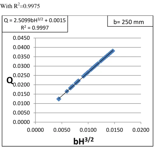
It also appears from Fig.3, that the discharge (Q) versus bH3/2 data falling on two different straight lines. It is further clear from Fig.4, in which Q versus bH3/2 data were plotted for weir width, b=250 mm, and Fig.5, in which data were plotted for weir widths, b=350 mm, 450 mm, and 550 mm. This phenomenon may be due to very large lateral curvature of streamlines for weirs with very narrow width b ≤ 250 mm. The corresponding best fit equation for b=250 mm is:
Q=2.5099bH3/2+0.0015 (16)
With coefficient of correlation R2 = 0.9997
And for b=350 mm, 450 mm and 550 mm, the best fit equation (Fig.5) is:
Q=2.7743bH3/2+0.0006 (17)
With R2=0.9975
Fig. 4 Discharge (Q) versus bH3/2 for all P and b=250 mm
Q = 2.6448bH3/2 + 0.0014
R² = 0.9864
0.01 0.015 0.02 0.025 0.03 0.035 0.04
0.0000 0.0050 0.0100 0.0150 0.0200
Q
bH
3/2Q = 2.5099bH3/2 + 0.0015
R2 = 0.9997
0.0000 0.0050 0.0100 0.0150 0.0200 0.0250 0.0300 0.0350 0.0400 0.0450
0.0000 0.0050 0.0100 0.0150 0.0200
bH
3/2
Q
b= 250 mm
FIG.2 CALIBRATION CURVE: DISCHARGE (Q) VERSUS HEAD (H) OVER THE RECTANGULAR WEIR
HEAD OVER THE WEIR CREST (H)
The fitted equation (7) and equation (8) shows an excellent matching as R2 is very near to unity. However, a best fit equation for all widths (b=250 mm, 350 mm, 450 mm and 550 mm) has been shown in Fig.3 and is given below:
Q=2.6448bH3/2+0.0014 (18)
With R² = 0.9864, which shows a very good matching of data.
Fig.5 Q versus bH3/2 for b = 350 mm, 450 mm and 550 mm and for all values of P.
VARIATION OF K (AS A FUNCTION OF DISCHARGE COEFFICIENT, Cd)
Define a new coefficient K, as a function of coefficient of discharge Cd and is given below:
𝑘=23√2𝐶𝑑 = 0.9428𝐶𝑑 (19)
Define also Reynolds number (Re) for open channel flow as follows:
𝑅𝑒=𝑔
1 2𝐻32
𝜈 (20)
The Reynolds number (Re) is further modified to:
Re*= 𝑅𝑒
104𝐶1 (21)
Where C1 is based on b/B ratio and is given in Table 1 [32 pp. 162].
Table 1 Variation of constant C1
S .No. b/B 𝐶1
1. 0.4166 0.035
2. 0.5833 0.046
3. 0.7500 0.055
4. 0.9166 0.068
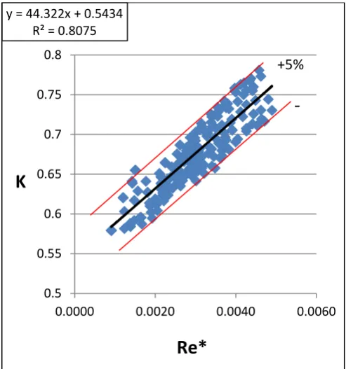
A graph between coefficient K versus Reynolds number Re* has been plotted in Fig.6 for all values of b/B and H/P ratios. In this Fig.6, a line of ± 5% is also drawn.
The best fit curve equation of K versus Re* is given below:
K = 44.322Re* + 0.5434 (22)
With a coefficient of correlation R2=0.8075. This fitted equation (13) shows a good correlation.
Fig.6 K versus Re* for all b and all P
PROCEDURE TO ESTIMATE DISCHARGE
The discharge over the sharp crested contracted rectangular weir can be estimated by measuring the head over the crest of the weir. The procedure for the estimation of the discharge is as follows:
1. Measure the head (H) over the crest of the weir. 2. Determine the constant C1 from the Table 1
corresponding to b/B ratio.
3. Calculate the Reynolds number (𝑅𝑒=𝐻�𝑔𝐻
𝜈 ).
4. Calculate the 𝑅𝑒∗=�𝑅𝑒
104� 𝐶12.6
5. Find the value of constant K using the equation (22).
6. Find 𝐶𝑑= 𝐾
0.9428
7. Estimate the discharge from the equation (2).
Q = 2.7743bH3/2 + 0.0006
R² = 0.9975
0.0000 0.0050 0.0100 0.0150 0.0200 0.0250 0.0300 0.0350 0.0400
0.0000 0.0050 0.0100 0.0150
bH
3/2Q
y = 44.322x + 0.5434 R² = 0.8075
0.5 0.55 0.6 0.65 0.7 0.75 0.8
0.0000 0.0020 0.0040 0.0060
K
+5%
Re*
CONCLUSIONS
From the present work following conclusions can be drawn:
1. Calibration curves (Q versus H) have been developed corresponding to b/B = 0.416, 0.583, 0.750 and 0.916.
2. A single curve between Q and bH3/2 has been prepared with correlation coefficient (R2=0.9864) near to unity, which shows that the relationship is independent of b/B and H/P ratios.
3. A unique expression for Coefficient K a function of coefficient of discharge (Cd) versus Reynolds Number
�𝑅𝑒∗= 𝑅𝑒
104𝐶12.6� is developed for all values of b/B
and H/P ratios.
4. A procedure has been developed to estimate the discharge (Q). The accuracy of the estimated discharges is within ± 5% for the range of present experimental data.
REFERENCES
[1] Asawa G.L. (2000). “Irrigation Engineering” New Age International (P) Limited, Publishers. Second Edition.
[2] Aydin I., Ger A.M., Hincal O. (2002). “Measurement of small discharges in open channels by slit weir”, Journal of Hydraulics Engineering, ASCE; Vol.128 (2):234–237.
[3] Aydin I., Sakarya A.B., Ger A.M. (2006). “Performance of slit weir”; Journal of Hydraulics Engineering, ASCE; Vol. 132(9):987–989.
[4] Aydin I., Sakarya A.B., Sisman Cigdem (2011). “Discharge formula for rectangular sharp crested weir”, Flow Measurement and Instrumentation; Vol. 22(2):144– 151.
[5] Aydin I., Gharahjeh S., Sakarya A.B., (2014). “Weir velocity formulation for sharp crested rectangular weirs”; Flow Measurement and Instrumentation”; Vol. (41):50-56.
[6] Baddour R.E. (2008). “Head discharge equation for sharp crested polynomial weirs”, Journal of Irrigation and Drainage Engineering; ASCE; Vol. (2):260-262.
[7] Bagheri S., Heidarpour M., (2010). “Application of free vortex theory to estimating discharge coefficient for sharp-crested weirs”; Bios stems engineering; Vol. 105: 423–427.
[8] Bagheri S., Heidarpour.M. (2010). “Flow over rectangular sharp-crested weirs” Journal of Irrigation Science; Vol. 28:173–179.
[9] Bagheri S., Heidarpour M. (2011). “Characteristics of flow over rectangular sharp crested side weirs”, Journal of
Irrigation and Drainage Engineering, ASCE; Vol. 138(6):541–547.
[10] Bagheri S., Kabiri S.A.R., Heidarpour M. (2014). “Discharge coefficient of rectangular sharp-crested side weirs, Part I: Traditional weir equation” Flow Measurement and Instrumentation; Vol. 35:109-115.
[11] Bansal R.K. (2010). “A Textbook of Fluid Mechanics and Hydraulic Machines” Laxmi Publications Ltd. New Delhi.
[12] Borghei S.M., Jalili M.R., Ghodsian M. (1999). “Discharge coefficient for sharp-crested side weirs in subcritical flow”, Journal of Hydraulic Engg. ASCE; Vol. 125(10):1051–1056.
[13] Bos M.G. (1989). “Discharge measurement structures” Wageningen: International Institute for Land Reclamation and Improvement, ILRI.
[14] Cheong H.F. (1991). “Discharge coefficient of lateral diversion from trapezoidal channel”. Journal of Irrigation and Drainage Engineering, ASCE; Vol. 117(4):461–475.
[15] Chow V.T. (2009). “Open Channel Hydraulics” Tata McGraw-Hill Publication.
[16] Coleman G.S., Smith D. (1923). “The discharging capacity of side weirs” In: Proceedings of the Institution of Civil Engineering, London, Selected Engineering Paper No.6.
[17] Ferro V. (2012). “New Theoretical Solution of the Stage Discharge relationship for Sharp Crested and Broad Weirs”. Journal of Irrigation and Drainage Engineering,
ASCE; Vol. 138 (3): 257-265.
[18] Franzini J.B. and Finnemore E.J. (1998). “Fluid Mechanics with Engineering Applications” Tata McGraw-Hill Publication, Eighth Edition.
[19] Garde R.J. and Mirajgaoker A.G. (2002). “Engineering Fluid Mechanics including Hydraulic Machines” Nem Chand and Bros. Roorkee, Second Edition (Reprint).
[20] Hager W.H. (1987). “Lateral outflow over side weirs”. Journal of Hydraulics Division, ASCE; Vol. 113 (4):491– 504.
[21] Hincal O. (2000). “Discharge Coefficient for Slit Weirs”. M.Sc. Thesis, Department of Civil Engineering; Middle East Technical University, Ankara Turkey.
[22] Jain A.K. (2009). “Fluid Mechanics and Hydraulic Machines” Khanna Publishers, Tenth Edition.
[23] Kandaswamy P.K., Rouse H. (1936). “Characteristics of flow over terminal weirs and sills”. Journal of Hydraulic Division ASCE, Vol. 83(4):1–13.
[24] Kindsvater C.E., Carter R.W. (1957). “Discharge characteristics of rectangular thin-plate weirs”. Journal of Hydraulic Division, ASCE, Vol. 83(6):1–36.
[25] Martinez R.E., Reca J., Morillas M.T., Lopez J.G. (2005). “Design and Calibration of Compound Sharp crested Weir”, Journal of Hydraulic Engineering; ASCE, Vol.131 (2):112-116.
[26] Nadesamoorthy T., Thamson A. (1972). “Discussion of ‘Spatially varied flow over side weirs”. Journal of Hydraulics Division; Vol. 98 (12):2234–2235.
[27] Pati S.K. (2010). “A Textbook of Fluid Mechanics and Hydraulic Machines”. Tata McGraw-Hill Publication, New Delhi. (Second Edition).
[28] Rajaratnam, N., and Muralidhar, D. (1971). “Pressure and velocity distribution for sharp-crested weirs.” Journal of Hydraulic Resources, ASCE; Vol. 9(2), 241–248.
[29] Ramamurthy A.S., Tim US, Rao M.V.J. (1987). “Flow over sharp crested plate weirs”. Journal of Irrigation and Drainage Engineering, ASCE; Vol. 113(2):163–172.
[30] Ramamurthy A. S., Qu J., Zhai C. and Vo D. (2007). “Multi slit weir characteristics”. Journal of Irrigation and Drainage Engineering, ASCE; Vol. 133(2):198–200.
[31] Ranga Raju K.G., Prasad B., Gupta S.K., (1979). “Side weirs in rectangular channels”. Journal of Hydraulics Division” ASCE; Vol. 105(5):547–554.
[32] Ranga Raju K.G. (2013). “Flow through Open Channels”. Tata McGraw-Hill Publications New Delhi Second Edition.
[33] Rehbock, T. (1929). “Discussion of Precise measurements by Schoder F.W. and Turner K.B.”, Trans ASCE; Vol. 93 :1143–1162.
[34] Shrivastava Rajesh (2013). “Flow Through Open Channels”, Oxford University Press, Second Edition.
[35] Sisman H.C. (2009). “Experimental Investigation on Sharp Crested Rectangular Weirs”; M.Sc. thesis: Department of Civil Engineering, Middle East Technical University Ankara (Turkey).
[36] Subramanya, K., (2011). ENGINEERING HYDROLOGY, 3rd edition, Tata McGraw Hill.
[37] Subramanya, K. (2011). “Flow in Open Channels”, Tata McGraw-Hill Publication, Third Edition.
[38] Subramanya K, Awasthy S.C. (1972). “Spatially varied flow over side weirs” Journal of Hydraulics Division, ASCE; Vol. 98(1):1–10.
[39] Swamee P.K. (1988). “Generalized rectangular weir equations”. Journal of Hydraulic Engg. Vol. 114(8):945– 949.
[40] Swamee P.K. (1988). “Discharge equations for rectangular sharp crested weirs”. Journal of Hydraulic Engg. Vol. 114(8):1082–1087.
[41] Swamee, P. K., Pathak, S. K., Agarwal, M., and Ansari, A. S. (1991). “Alternative linear weir design.” Journal of Irrigation and Drainage Engineering, ASCE Vol. 117 (3): 311–323.
[42] Swamee P.K., Pathak S.K., Mohan M., Agrawal S.K., Ali M.S. (1994). “Subcritical flow over rectangular side weir” Journal Irrigation and Drainage Engineering”, ASCE; Vol. 120(1):212–7.
[43] Swamee P.K. (1998). “Discharge equation for rectangular slots” Journal of Hydraulic Engineering, ASCE; Vol. 124(9):973-974.
[44] Vatankhah, A. R., and Kouchakzadeh, S. (2009). “Discussion of Head-Discharge Equation for sharp-crested polynomial weir by R. E. Baddour. ” Journal of Irrigation and Drainage Engineering, ASCE, Vol. 10; 393–395.
[45] Vatankhah, A. R. (2010). “Flow measurement using circular sharp-crested weirs.” Flow Measurement and Instrumentation, Vol. 21(2), 118–122.
[46] Vatankhah Ali R., (2012). “Head Discharge equation for Sharp Crested Weir with Piecewise-linear Sides”, Journal of Irrigation and Drainage Engineering, ASCE, Vol. 138(11):1011-1018.
[47] Zhang, Xin (2010). “Hydraulic relations for clinging flow of sharp crested weirs”. Journal of Hydraulic Engineering, ASCE; Vol. 136 (6):385-390.
First Author Rahul Pandey has obtained his M.Tech degree in Water Resources Engineering (2015) from MANIT, Bhopal. Presently he is working as JE in Military Engineer Services at Bamrauli Allahabad.
Second Author Prof. S. K. Mittal is working as Professor in Civil Engineering department of MANIT, Bhopal. He has published nearly 100 papers in international journals and conferences. His major area of research is hydraulics, irrigation, and fluid mechanics.
Third Author Prof. M.K.Choudhary is working as Associate Professor in Civil Engineering department of MANIT, Bhopal. He has published nearly 25 research papers in international journals and conferences. His major area of research is surface water hydrology.