MAINTAINING THE COMFORT TEMPERATURE OF
SYSTEM BY USING EAHE
Snehil Tripathi
1, Ajay Kumar Tiwari
2, Ashutosh Kumar Singh
3 1, 2Research Scholar,
3Professor, Millennium Institute of Technology, RGPV Bhopal (India)
ABSTRACT
An earth-air heat exchanger (EAHE), also known as an earth tube heat exchanger or Canadian well, is a system
for cooling and heating buildings using the ground as a heat sink/source. The earth–air heat exchanger (EAHE)
is a promising technique which can effectively be used to reduce the heating/cooling load of a building by
preheating the air in winter and vice versa in summer. In the last two decades, a lot of research has been done
to develop analytical and numerical models for the analysis of EAHE systems. Many researchers have
developed sophisticated equations and procedures but they cannot be easily recast into design equations and
must be used by trial-and-error. The method to calculate the earth’s undisturbed temperature (EUT) and more
recently developed correlations for friction factor and Nusselt number are used to ensure higher accuracy in the
calculation of heat transfer. The developed equations enable designers to calculate heat transfer, convective
heat transfer coefficient, pressure drop, and length of pipe of the EAHE system. A longer pipe of smaller
diameter buried at a greater depth and having lower air flow velocity results in increase in performance of the
EAHE system.
Keywords: EAHE, Fins, Reynolds’s No., EUT, Heat Transfer.
I.INTRODUCTION
An earth-to-air heat exchanger draws air through covered pipes. As temperature of the ground below 2.5 m to 4
m is practically constant, it considerably reduces ambient air temperature variation. It therefore provides space
conditioning during the year, with the incoming air being heated in the winter and cooled in the summer by
means of earth coupling.
Earth tubes are low technology, sustainable flaccid cooling-heating systems utilized mostly to preheat air intake.
Due to ground properties the air temperature at the pipe outlet maintains moderate values all around the year.
Temperature fluctuates with a time lags (from some days to a couple of months) mainly relative to the depth
considered. Temperature remains in the comfort level range (15-27 c).
In recent years, ground heat source heat pump systems have become increasingly popular for use in residential
and commercial buildings. These systems include several different variations, all of which reject heat and/or
extract heat from ground:
(1) ground-coupled heat pump (GCHP) systems;
(2) Surface water heat pump (SWHP) systems;
a. Standing column well (SCW) systems;
b. Open loop groundwater systems.
This technology is not recommended for cooling of humid climates due to moisture reaching dew pint and often
remaining in the tubes. However, in southern European coastal regions as in Greece where the climate remains
dry and hot. In such locations these systems could have exciting results.
The material of a pipe can be anything from plastic, metal or concrete. However concrete should be avoided in
order not to be dependent on carbon filtration UV sterilization for the stuffy air coming out of concrete earth
tubes.
1.2 Working Principle of Earth Air Heat Exchanger
Earth air heat exchanger exchanges heat between air and ground by the process of convection and by conduction
it transfers heat to the tube wall.
1.2.1 Summer Conditions
Fig 1 Working of EAHE in summer condition
i) Hot air enters into the tube ii) Air loses heat to the ground iii) Cool air enters into the house
1.2.2 Winter Conditions
Fig 2 Working of EAHE in winter condition
1.3 DESIGN PARAMETERS OF EARTH AIR HEAT EXCHANGER
1.3.1 Location
If the purpose of the system is to heat, then it must be located in the sunny area. If the purpose of the system is
to cool, then it should be located near shaded area of a lake or river.
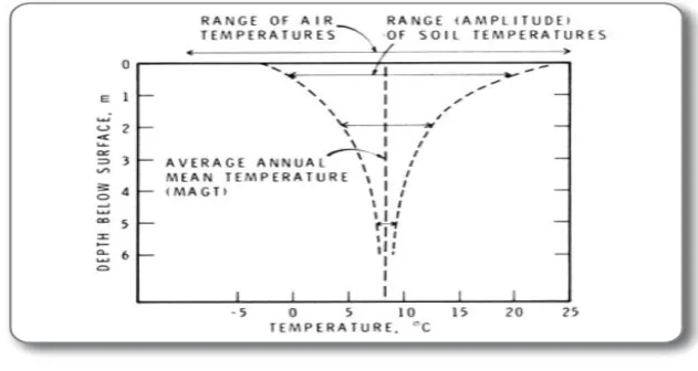
1.3.2 Depth of Pipe
Fig 4 Temperature v/s Depth
Pipe should be buried as deep as possible but favorable depth can vary from 1.5 m to 3 m. A system designed
for cooling requires more depth of pipe than a system designed for heating in same location.
II. PROBLEM FORMULATION
The main objective of my experimental work is to study the variation in cooling effects caused by Earth Air
Exchanger in summer climate condition by using fins and without fins in series connection. In summer climate
conditions, ground temperature is lower than atmospheric temperature. Hence air flowing through the buried
pipe exchange heat with underground earth surface in summer climate condition. In this experiment, blower
sucks atmospheric air into the pipe and circulates through the buried pipe, due to which air gets cooled. The
cooled air is circulated into the delivery pipe for cooling in summer.We compare whether fins arrangement is
better or without fins for horizontal series arrangement.
III. EXPERIMENTAL SETUP
The setup consists of without fins and fins arrangement of pipe along with inlet and outlet section, control valve,
Fig. 5 Experimental setup of series connection (2.5 m) without covered soil
The Earth Air Heat Exchanger in series conncetion as shown in fig. consists of horizontal pipe of inner diameter
of 64 mm with total length of 19 m. Three pipes made up of GI of length 3 m each are connected in series and
buried at a depth of 2.5 m in ground with dry soil. The series arrangement of GI pipe is connected to a common
intake and outlet maniforld for air passage. Atmospheric air was sucked during the pipe by means of centrifugal
blower by a 3 phase, 2 hp, 230 V and 2800 rpm motor. The blower is used to suck the hot ambient air through
the pipelines and delivered the cold air for required place. The mass flow rate of air was measured by orifice
meter.
Fig 6 Experimental setup of series connection (2.5 m) without covered soil with fins
IV. METHODOLOGY
As we have discussed the data is collected experimentally by using different components. The flow of air
changes by using control value. The data obtained through experiment has been used to determine the Nusselt
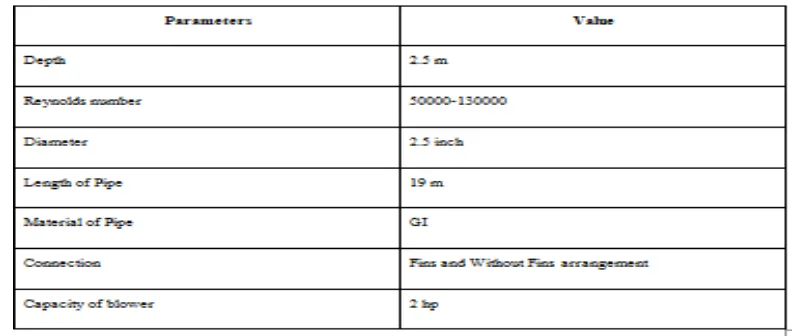
4.1 Experimental Conditions
Table 1 : Experimental Parameter Range
4.1 Data Reductions
Mean bulk air temperature (Tfav)
Simple arithmetic mean of measured inlet and exit temperatures of air under testing
Tfav = (Ti + To)/2 Where, Ti = Inlet temperature of air in Celsius
Te = Outlet temperature of air in Celsius
Mean Pipe air temperature (Tpav)
Thermocouple wires are arranged at equal distance on pipe. Hence average reading of all points are
Tpav = (T1 + T2 + T3 + T4 + T5 + T6)/6
Where,
Tpav = temperature of pipe at different locations of pipe
Pressure drop across the orifice plate (
P
o)5
/
1
81
.
9
P
h
mWhere,
h
= difference of mercury level in U tube manometerm
Mass flow rate measurement (m in kg/s) 5 . 0 4
]
)
1
(
/
)
(
2
[
C
A
p
p
m
dWhere,
=d2/d1Cd = coefficient of discharge of orifice meter i.e. 0.62
A= Area of orifice plate, m2
p= density of air in kg/m3
Velocity of air (V)
V = m/(
A
)
Where,
A = area of pipe in m2
Reynolds number (Re)
Re = V Dh/
Where,
= kinematic viscosity of air at t in m2/s
Heat transfer rate (Q)
Qa = m x Cp x (To-Ti)
Where,
m = mass flow rate
Cp = heat capacity
Ti = initial temperature
To = final temperature
Heat transfer coefficient (h)
h = Qz / Ap (tpav - tfav)
Ap is the heat transfer area assumed to be the corresponding pipe area
Nusselt Number (Nu)
Nu = h Dh / k
Where,
k = thermal conductivity
Dh = hydraulic diameter
Coefficient of Performance
Cop = Qa / W
Where,
Qa = Heat Transfer Rate
W = Work done by Blower
VI. RESULTS
6.1 Obsevation Tables
Serial
No.
Mercury
deflection
(cm)
Inlet air
temp.
(Celsius)
Outlet air
temp.
(Celsius)
Pipe Temp.
(Celsius)
Avg. air
temp.
(Celsius)
Temp.
Difference
1 1 42.51 37.32 35.11 39.91 5.19
2 2 39.22 35.09 34.13 37.15 4.13
3 3 36.76 33.50 32.03 35.13 3.26
4 4 34.12 30.85 29.71 32.52 3.38
Table 2 Observation table for series combination 2.5 inch GI pipe without fins
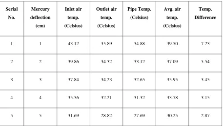
Serial No. Mercury deflection (cm) Inlet air temp. (Celsius) Outlet air temp. (Celsius) Pipe Temp. (Celsius) Avg. air temp. (Celsius) Temp. Difference1 1 43.12 35.89 34.88 39.50 7.23
2 2 39.86 34.32 33.12 37.09 5.54
3 3 37.84 34.23 32.65 35.95 3.45
4 4 35.36 32.21 31.32 33.78 3.15
5 5 31.69 28.82 27.69 30.25 2.87
Table 3 Observation table for series connection 2.5 inch GI pipe with fins
Serial
No.
Reynolds
No. Re
Velocity Mass flow
rate Kg/s Heat transfer Q in watt Convective heat transfer
coeff. h In W
m2/k
Nusselt
number
No.
Cop
1 55268.30 12.91 0.0507 265.44 14.59 26.49 0.1779
2 79026.28 18.91 0.0718 298.73 26.11 65.27 0.200
3 96791.97 22.40 0.0879 285.55 24.57 61.42 0.1933
4 112490.60 25.86 0.101 343.76 32.29 82.02 0.230
Table 4 Results of different parameters of 2.5 inch series connection without fins
Serial
No.
Reynolds No.
Re
Velocity Mass flow
rate Kg/s
Heat
transfer Q
in watt
Convective
heat transfer
coeff. h In W
m2/k
Nusselt
number No.
Cop
1 55265.30 12.90 0.0506 368.39 21.02 52.56 0.2469
2 79026.11 18.93 0.0718 400.50 31.125 77.81 0.2684
3 96759.23 22.44 0.088 305.72 24.454 61.13 0.2049
4 112492.60 25.85 0.102 323.54 34.71 86.79 0.2168
5 125775.40 28.90 0.110 317.90 32.779 81.94 0.2130
Table 5 Results of different parameters of 2.5 inch series connection with fins
6.2 Comparison of Cop of The Set Up With or Without Fin
Fig.8 Comparing Nusselt number and Reynolds number for with and without combination
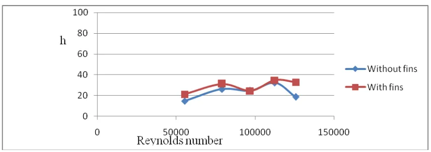
Fig 9 Comparing Convective heat transfer and Reynolds number for with and without fins
REFERENCE
[1]. Bansal Vikas, Misra Rohitm, Agrawal Ghanshyam Das, Mathur Jyotirmay. Performance analysis of
earth-pipe air heat exchanger for winter heating. Enegry and Building 2009; 41:1151-4.
[2]. Bansal Vikas, Misra Rohitm, Agrawal Ghanshyam Das, Mathur Jyotirmay. Performance analysis of
earth-pipe air heat exchanger for summer cooling. Enegry and Building 2010; 42:645-8.
[3]. Bansal NK, Sodha MS. Bhardwaj SS. Performance of earth-air tunnel system. Energy Research 1983;
7(4):333-41.
[4]. Manoj kumar Dubey, Dr. J.L.Bhagoria, Dr. Atul lanjewar , Earth Air Heat Exchanger in Parallel
Connection
[5]. M. Santamouris, A. Argiriou, M. Vallindras, Design and operation of a low energy consumption passive
solar agriculture greenhouse, Solar Energy 52 (1994) 371-378.
[6]. A. Tombazis, A Argirion, M. Santamouris, Performance evaluation of passive and hybrid cooling
[7]. A.K. Khatry, M.S. Sodha, M.A.S. Malik, Periodic variation of ground temperature with depth and time,
Solar Energy 20 (1978) 425-427.
[8]. Goswami DY, Ileslamlou S. Performance analysis of a closed loop climate control system using
undergorund air tunnel. Journal of Sloar Energy Engineering 1990; 112:76-81.
[9]. Ozgener L, Ozgner O. Energetic performance test of an undergound air tunnel system for greenhouse
heating. Energy 2010;35(10):4079-85.
[10].Ozgener L, Ozgner O. Exergoconomic analysis of an underground air tunnel system for greenhouse