STRENGTHENING OF REINFORCED CONCRETE BEAMS WITH GLASS FIBER REINFORCED POLYMER SHEETS WITH DIFFERENT CONFIGURATIONS IN SHEAR AND FLEXURE
Full text
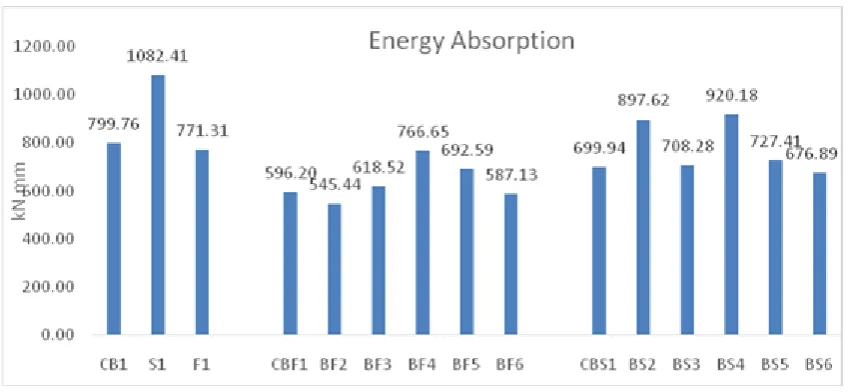
Figure


Related documents
Poster Presentation: STABILITY Study: A Multicentre Randomized Clinical Trial Comparing Anterior Cruciate Ligament Reconstruction With and Without Lateral Extra- Articular
In this study, rainfall data for the years 2001 to 2012 have been analyzed in terms of temporal and spatial characteristics in order to identify the change
In this report, we evaluated the humoral immune response induced by the live spore anthrax vaccine in Boer goats using the anti-PA ELISA, an in vitro toxin neutralization
Vol 10, Issue 8, 2017 Online 2455 3891 Print 0974 2441 ANTIBACTERIAL AND CYTOTOXIC POTENCIES OF STILBENE OLIGOMERS FROM STEM BARKS OF BAOTI (DRYOBALANOPS LANCEOLATA) GROWING IN
Table 5.8: ACF and HL Statistics Simulation Side for Short Failure 70% Constant Demand Case. Output Simulation Output Simulation -
In Drosophila, mutations in double-strand DNA break (DSB) repair enzymes, such as spn-B , activate a meiotic checkpoint leading to dorsal-ventral patterning defects in the egg and
