Concurrent PV Conditioner with Interleaved
Buck Converter Using Model Predictive
Control
Mrs.M.Deva Brinda1, Uggumudi Vishnu Vardhan2 , Thenmugilan E3 , Sathish Kumar M4, Ragul R5
Assistant Professor (Selection Grade), Dept of EEE, Easwari Engineering College, Chennai, Tamil Nadu, India1
UG Student, Dept. of EEE, Easwari Engineering College, Chennai, Tamil Nadu, India2
UG Student, Dept. of EEE, Easwari Engineering College, Chennai, Tamil Nadu, India3
UG Student, Dept. of EEE, Easwari Engineering College, Chennai, Tamil Nadu, India4
UG Student, Dept. of EEE, Easwari Engineering College, Chennai, Tamil Nadu, India5
ABSTRACT: The main objective of this paper is to design a low cost, high efficient, photovoltaic inverter system
with reduced number of components and overall losses. A real time module of PV system with interleaved buck DC-DC converter is designed where Maximum power point tracking is incorporated with Model Predictive based Incremental Conductance which reduces the complexity and increases the efficiency. The occurrence of inter-harmonic and sub-harmonic distortions is addressed by adopting a power point tracking method along with interleaved buck converter. Furthermore, the efficiency can be increased to greater value using model predictive control method with incremental conductance as base. This project work further focuses on a novel approach to design single-phase inverter topology. The inverter is supported with an energy buffer circuit, a dc-dc conversion circuit and an H-bridge circuit. The energy buffer coupled with the inverter circuit will be capable of producing a multilevel voltage according to improve the Total Harmonic Distortion (THD) of the output of the inverter. The present design is capable of operating with 12V/24V panels and 12V/24V batteries with up to 5A output current.
KEYWORDS
:
Maximum Power Point Tracking, Model Predictive control, Incremental Conductance, Total HarmonicDistortion.
I.INTRODUCTION
The vitality deficiency and the climate contamination have been the real constraints for the human improvement. Photovoltaic (PV) sources are one of the critical players on the planet's vitality portfolio and will turn into the greatest commitments to the power age among all sustainable power source applicants by year 2040 on the grounds that it is really a perfect, emanation free inexhaustible electrical age innovation with high unwavering quality. The assignment of a greatest power point tracker (MPPT) in a photovoltaic (PV) vitality transformation framework is to constantly tune the framework with the goal that it draws most extreme power from the sun oriented cluster paying little heed to climate or load conditions.
conversion of DC-AC, because the total harmonics thus produced by the multilevel inverter is low while compared with other types of inverter [2].
The input of the multilevel inverter is fed through the interleaved buck converter. The buck converter is used to step down the input supply from the solar panel [5]. The output thus produced from the solar panel may vary based upon the sun’s irradiation. In order to make the output of the solar panel as constant Maximum power point tracking (MPPT) is used [9][10]. The current and the voltage of the multilevel inverter can be controlled by using the artificial controller. P, PI, PID are some of the artificial controllers.
II.SYSTEM MODEL AND ASSUMPTIONS
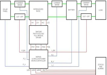
The PMP7605 is developed around the MSP430F5132 controller IC. The design is targeted for small and medium power solar charger solutions. The present design is capable of operating with 12V panel and 12V battery with up to 20A output current. However, it can be easily adapted to 48V systems by just changing the MOSFETs to 100V rated parts. Also, it is possible to increase the current to 40A by using TO-220 package version of the same MOSFETs used in the design. The design has an operating efficiency of above 97% at full load in a 24V system. For 12V systems the efficiency is above 96%. This efficiency Fig. includes the losses in battery reverse protection MOSFET and panel reverse flow protection MOSFET, which are part of the design.
The high efficiency is the result of the low gate charge MOSFETs from TI used in the design, and the interleaved buck topology used. The interleaved buck topology reduces the component stresses by a great extent. Another feature is the relatively small sized components used, possible due to the high operating frequency (~200 KHz per stage). The design has built-in battery charge profiles for 12V Lead acid battery. The circuit takes only under 10mA of standby current while operating from battery. There is also a provision to connect a load to the battery with overload and short circuit cut-off built in. The design presently uses ‘perturb and observe’ algorithm for MPP tracking. This gives fast acquisition of MPP operation. Software programmable alarms and indications are provided in hardware, but are left non-confide. Surge protection and EMI filtering components are not present on this design, and has to be added depending upon required specification levels.
III. MODEL PREDICTIVE CONTROL
The main characteristic of MPC is predicting the future behaviour of the desired control variables until a predefined step ahead in horizon of time. The predicted variables will be used to obtain the optimal switching state by minimizing a cost function. The model used for prediction is a discrete-time model which can be presented as a state space model [10]. The MPC for power electronics converters can be designed using the following steps: [9]
• Modelling of the power converter identifying all possible switching states and its relation to the input or output voltages or currents.
• Defining a cost function that represents the desired behaviour of the system.
• Obtaining discrete-time models that allow one to predict the future behaviour of the variables to be controlled. The designed controller should consider the following tasks:
• Predict the behaviour of the controlled variables for all possible switching states. • Evaluate the cost function for each prediction.
• Select the switching state that minimizes the cost function.
We can mathematically express the current produced by the solar cell as
I= IL − ID − ISH, (1)
Where, I= output current (A), IL=source current (A), ID= diode current (A), ISH= shunt current (A).
In this scheme measured variables, X (K) are used in the model to calculate predictions, X (K+1) of the controlled variables for each one of the n possible actuations, that is, switching states, voltages, or currents. Then these predictions are evaluated using a cost function which considers the reference values, X (K+1) design constraints, and the optimal actuation, S, is selected and applied in the converter.
The general form of the cost function, g, subject to minimization can be formulated as
g = [ 1 (K + 1) – X*(K + 1) ] +λ1[X2 (K + 1) – X*2 (K + 1)]+…+λn[ n ( + 1)−X*n (K + 1)]
Where, λ is the weighting factor. To select the switching state which minimizes the cost function g, all possible states are evaluated and the optimal value is stored to be applied next. The power converter can be from any topology and number of phases, while the generic load. It can represent an electrical machine, the grid, or any other active or passive load.
IV.MAXIMUM POWER POINT TRACKING USING MODEL PREDICTIVE CONTROL
The low conversion efficiency of PV systems is a significant obstacle to their growth; therefore Maximum Power Point Tracking (MPPT) is required to ensure the maximum available solar energy is harnessed from the solar panel. Many MPPT methods have been suggested over the past few decades; the relative merits of these various approaches are discussed. The critical operating regime is low insolation. Capturing all of the available solar power during low insolation periods can substantially improve system performance. An effective MPPT controller and converter can use available energy to significantly reduce the amount of installed PV. The main contribution of this section is to improve the P&O method performance by predicting the error one step ahead in the horizon through model predictive control technique. The proposed method has faster response than conventional P&O under rapidly changing atmospheric conditions. A super lift Luo converter is chosen as a DC/DC converter. P&O determines the reference current for the MPC which determines the next switching state. This technique predicts the error of the next sampling time and based on optimization of the cost function g, the switching state will be determined.
The inputs to the predictive controller are the PV system current and voltage, and the reference current. Now after determination of the reference current using the procedure shown in Fig. 3, the cost function can be obtained as follows
Where, S is the switching state, Ts is the sampling time.By increasing the number of steps to two or three, the computation time will be increased, but better control performance expected to be achieved.
The Limitations of P&O method can be summarized as follows: The power tracked by the P&O method will oscillate and perturb up and down near the maximum power point. The magnitude of the oscillations is determined by the magnitude of variations of the output voltage. There is a misjudgment phenomenon for the P&O method when weather conditions change rapidly. The operating point is then farther away from the maximum power point. If the sun irradiance continuously increases, the distance between operating point and maximum power point will be farther. Consequently, the power loss of the power tracked by the P&O method will oscillate and perturb up and down near the maximum power point. The magnitude of the oscillations is determined by the magnitude of variations of the output voltage. There is a misjudgment phenomenon for the P&O method when weather conditions change rapidly. The operating point is then farther away from the maximum power point. If the sun irradiance continuously increases, the distance between operating point and maximum power point will be farther. Consequently, the power loss of PV modules will increase, and the efficiency of the PV system will reduce. The value of generally varies between 0.64 and 0.85 can be calculated by analysing the PV system at a wide range of solar radiations and temperatures. Advantage of model predictive control, Improve the efficiency, Predetermination of future error prevents oscillations lesser than other methods, Tracks the maximum power faster.
The power tracked by the P&O method will oscillate and perturb up and down near the maximum power point. The magnitude of the oscillations is determined by the magnitude of variations of the output voltage. There is a misjudgment phenomenon for the P&O method when weather conditions change rapidly. The operating point is then farther away from the maximum power point. If the sun irradiance continuously increases, the distance between operating point and maximum power point will be farther. Consequently, the power loss of PV modules will increase, and the efficiency of the PV system will reduce. The value of generally varies between 0.64 and 0.85 can be calculated by analysing the PV system at a wide range of solar radiations and temperatures. Advantage of model predictive control, Improve the efficiency, predetermination of future error prevents oscillations lesser than other methods, tracks the maximum power faster.
V. SIMULATION AND RESULTS
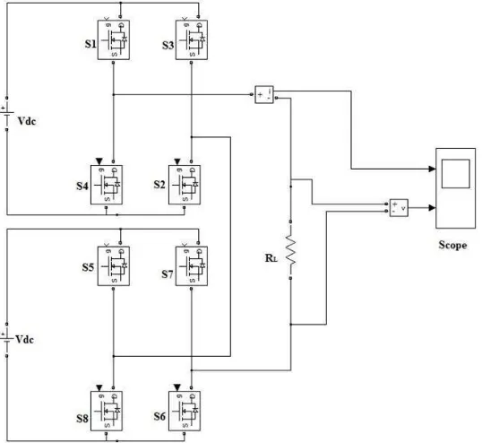
A) Multilevel Inverter
Cascaded Multilevel inverter design through the MATLAB simulation is given below. The output for the cascaded multilevel inverter is given in the figure 2 and 3.
Fig. 3 Output for the MLI
B) Maximum Power Point Tracking
Solar M-file coding for MPPT and PV simulation is given in the Fig. 4. The overall open loop model is given in the Fig. 5. The closed loop of boost converter is given in the Fig. 4.
The modeling and simulation of the whole system has been done in MATLAB-SIMULINK.
Fig. 4 M-file coding for MPPT and PV simulation
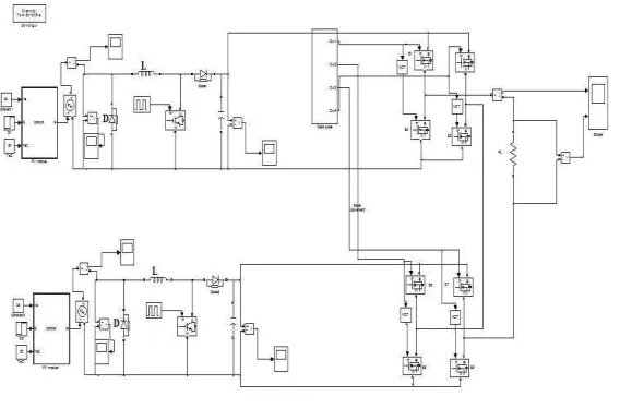
C) Closed Loop Model
The block diagram of the complete circuit is shown in the Fig. 6. This includes the PV module, buck converter, multilevel inverter and control circuit.
The modeling and simulation of the whole system has been done in MATLAB-SIMULINK
Fig. 6 Closed loop model
VI. PERFORMANCE AND WAVEFORMS
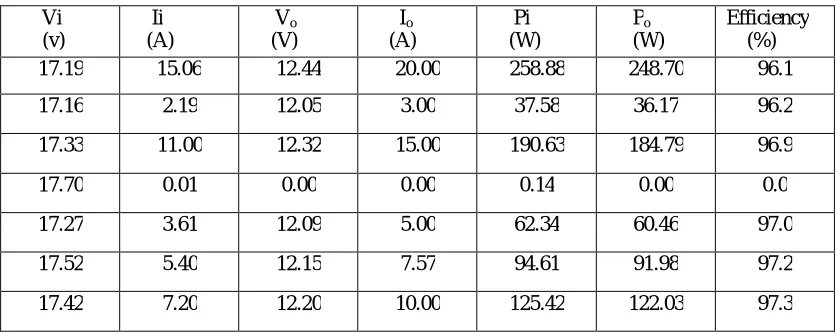
TABLE 1 TEST DATA FOR 12V SYSTEM
Vi (v)
Ii (A)
Vo
(V)
Io (A)
Pi (W)
Po
(W)
Efficiency (%) 17.19 15.06 12.44 20.00 258.88 248.70 96.1
17.16 2.19 12.05 3.00 37.58 36.17 96.2
17.33 11.00 12.32 15.00 190.63 184.79 96.9
17.70 0.01 0.00 0.00 0.14 0.00 0.0
17.27 3.61 12.09 5.00 62.34 60.46 97.0
17.52 5.40 12.15 7.57 94.61 91.98 97.2
A) GATE WAVEFORM
Fig. 7 12V system, 20A load. Top and bottom gate waveforms show dead-time implementation.
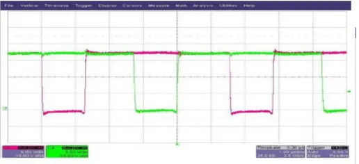
B) SWITCHING NODE WAVEFORMS
Fig. 8 12V system, 20A load Individual channel switch nodes show interleaved operation
C) MPP ACQUISITION
VII.CONCLUSION
In this paper a maximum power point tracking using model predictive control method for standalone Photo Voltaic (PV) application is designed and implemented successfully in real time. The project on successful completion is developed into a product meeting the IEC standards and having an edge over the other commercially available standalone solar power condition unit in the market as it has a less THD due to implementation of an energy buffer and uniform sampling and high out generated with higher efficiency to suit a low cost affordable module. The simulated result has been generated using Webench and MATLAB and it has been found to match with our expected results .When this is applied in a real-time application, it automatically adjusts any deficiency in current, power to the load. The future scope of this work can be to implement the proposed inverter topology to interact with the grid for exchange of power. This can be done by active frequency and voltage matching of the output parameters of the inverters to synchronize with that of the grid in real time. The use of electrolytic capacitors in the energy buffer can be replaced with ceramic disc capacitors for improved reliability.
ACKNOWLEDGMENT
The authors would like to thank
Asst.Professor(Sl.Gr.) Mrs.M.Deva Brinda and Faculty Members, Department of Electrical and Electronics Engineering, Easwari Engineering College, Chennai, Tamil Nadu, for many insightful discussions.REFERENCES
[1] J.M. Enrique, E. Duran, M.S. Cardona, J.M. Andujar, “Theoretical Assessment of the Maximum Power Point Tracking Efficiency of Photovoltaic Facilities with Different Converter Topologies”, Sol. Energy, Vol. 81, pp. 31-38, 2007.
[2] CORTES, P. WILSON, A. J. RODRIGUEZ, J. "Model predictive current control of cascaded h-bridge inverters," IEEE Transactions on Industrial Electronics, 56(8):2691-2699, Agosto 2010.
[3] J. Rodriguez, M. P. Kazmierkowski, J. R. Espinoza, P. Zanchetta, H. Abu-Rub and H. A. Young, State of the Art of Finite Control Set Model Predictive Control in Power Electronics, IEEE Transactions on Industrial Informatics, 9, 2013, 1003-1016,.
[4] M. B. Shadmand, M. Mosa, R. S. Balog, and H. A. Rub, An Improved MPPT Technique of High Gain DC-DC Converter by Model Predictive Control for Photovoltaic Applications,IEEE Applied Power Electronics Conference & Exposition, 2014.
[5] G. Paul, S. A. Kannan, N. Johnson, and J. George, "Modeling And Analysis of PV Micro-Inverter", International Journal Of Innovative Research in Electrical, Electronics, Instrumentation and Control Engg., Vol. 2, Issue 2, (2014).
[6] D. Zhu & G.Hug-Glanzmann,”Real-time control of energy Storage devices in future electric power systems,” in Proc.2011 PowerTech conf. pp.1-7.
[7] [7] C.Govindaraju and Dr.K.Baskaran ,” Optimized Hybrid Phase Disposition PWM Control Method for Multilevel Inverter”, International Journal of Recent Trends in Engineering, Vol 1,No. 3,pp. 129-134, may 2009.
[8] L. Xie and M.D.Ilie,”Model predictive economic/environmental dispatch of power systems with intermittent resources,” in Proc. 2009 IEEE PES General Meeting,pp.1-6.
[9] J. Surya Kumari, Dr. Ch. Sai Babu and A. Kamalakar Babu,”Design and Analysis of P&O and IP&O MPPT Techniques for Photovoltaic System,” International Journal Of Modern Engineering Research (IJMER) Vol.2, Issue.4, Pp-2174-2180 July-Aug. 2012.
[10] Z. Peng, W. Yang, X. Weidong, and L. Wenyuan, “Reliability Evaluation of Grid-Connected Photovoltaic Power Systems”, IEEE Trans on Sustainable Energy, 3, 379-389,2012.
[11] J. H. Lee, H. S. Bae, and B. H. Cho, "Advanced Incremental Conductance MPPT Algorithm with a Variable Step Size," 2006.
[12] B. S, Thansoe, N. A, R. G, K. A.S., and L. C. J., "The Study and Evaluation of Maximum Power Point Tracking Systems," International Conference on Energy and Environment 2006 (ICEE 2006), pp. 17-22, 2006.
[13] T.S.Ustun and S. Mekhilef, "Effects of a Static Synchronous Series Compensator (SSSC) Based on Soft Switching 48 Pulse PWM Inverter on the Power Demand from the Grid," Journal of Power Electronics, vol. 10, pp. 85-90, 2010.
[14] T. P. Nguyen, "Solar Panel Maximum Power Point Tracker," in Department of Computer Science & Electrical Engineering: University of Queensland, pp. 64,2001.
[15] S.Mekhilef, "Performance of grid connected inverter with maximumpower point tracker and power factor control,"International Journal of Power Electronics, vol. 1, pp. 49-62, 2008.