IJEDR1602303
International Journal of Engineering Development and Research (www.ijedr.org)1711
1SAL College of Engineering, Ahmedabad,Gujarat, India2,3,4C.U.Shah College of Engineering, Surendranagar,Gujarat, India
________________________________________________________________________________________________________
Abstract - Nowadays use of data acquisition is increased. They are being used in applications such as: material handling, agriculture and many more. Data acquisition comprise of many analogand digital sensors i.e. humidity, temperature, light dependant resistors (LDR),reed switch, piezoelectric, acoustic and many more. Mostly Data acquisition transmits information to the control room. It is necessary to acquire real time data in graphical format to know the condition of the environment. This work deals with only real time wireless multichannel data acquisition. Here in this implementation using Arduino UNO R3 and WIRDIN 1186 wireless module for transmitting the information to the control room. Control room has another WIRDIN 1186 wireless module to receive the information from the sensors mounted in plant. Control room receives the information in MATLAB and we use MATLAB as a graphical user interface.
Index Terms - Arduino UNO, WIRDIN 1186 wireless module, CP2101 serial to USB module, Multi-channel data acquisition, Wireless sensor network, Analog sensors.
________________________________________________________________________________________________________
I.INTRODUCTION
Data acquisition (DAQ) involves the collection and processing of data for use in automated control, and programming is an integral part for data acquisition (DAQ) systems. It is impossible to use Automation without using data acquisition. Even the most basic system requires some feedback, which processes this data, and calculates a real-world distance from the voltage, and sends the data back out in the form of a display. Most of this is accomplished through programming[9]. As the requirements of the system more sensors will be added and the DAQ system will become more complex.
Most DAQ systems involve both a microprocessor and a personal computer (PC). For microcontrollers, all have the ability to read digital and analog inputs and change digital outputs (digital I/O). Sensor information's are transmitted serially via Arduino and WIRDIN wireless module to the control room which receives the signal serially via another WIRDIN module and plotting it on MATLAB (Real time)[10].
Here Wireless DAQ got six sensors. The sensors are Light dependent resistor (LDR), DHT11 for Humidity, Piezoelectric for Vibration, Acoustic sensor for Noise, Reed switch for external Magnetic Interference and LM35 as temperature sensor. User can acquire data from any sensor using Matlab Graphical User Interface (GUI). Sensors have Arduino UNO microcontroller and WIRDIN wireless module[5][16].
IJEDR1602303
International Journal of Engineering Development and Research (www.ijedr.org)1712
Figure 2 Arduino UNO with descriptionII.ARDUINOUNOCONTROLLERANDSENSORINTERFACING
Arduino is a tool that makes the computers to sense and control the physical world. It's an open-source physical computing platform based on a simple microcontroller board, and a development environment for writing software for the board. Arduino can be used to develop interactive objects. Taking inputs from a variety of switches or sensors, controlling of variety of lights, motors, and other physical outputs can be achieved. Projects of Arduino can be stand-alone, or they can be communicating with software running on the computer (e.g. Flash, Processing, MaxMSP)[11][15]. The boards can be assembled by hand or purchased preassembled; the open-source IDE can be downloaded for free. In this research work Arduino UNO has been utilized. It has 14 digital I/O and 6[4]
Analog I/O. It works on +5volts DC, 10 bit analog to digital converter and 14Kb ROM. (www. ATMEL.com). Fig.2 shows the image of an Arduino UNO controller. Table 1 shows the specifications of the microcontroller[14].
ARDUINO INTERFACING WITH SENSORS
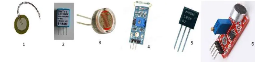
Fig. 3 shows six sensors utilized in this work with Arduino UNO. Hardware connections are shown in fig 5. The fritzing software is used to simulate the circuit. The simulated circuit is shown in fig 4. The first one is Piezoelectricvibration sensor. The second one is humidity sensor (DHT11). Third sensor is LDR. Fourth one is Reed switch. Fifth one is LM35 temperature sensor the last one is Acoustic noise sensor. It should be notified that Vcc (input power supply) and GND (ground) are taken common from each sensor, so six sensors could have one common Vcc and a common GND[2]. This Vcc can be taken from Arduino UNO.
Analog sensors, such as a Temperature Sensors (LM35) often work like a variable resistor the resistance of which is directly influenced by the condition it measures (in the case of the photocell it is the amount of light). Its sensitivity is 10mv/0C. Its range is -55 to 100 0C[1][3]. Its middle pin is connected with Arduino’s analog pin 0.
A piezoelectric sensor is a device that uses the piezoelectric effect, to measure changes in pressure, acceleration, temperature, strain, or force by converting them to an electrical charge.. Here this sensor’s pin is connected with analog pin No.4
There is a low cost DHT temperature & humidity sensors [2][17]. These sensors are very basic and slow. The DHT sensors are made of two parts, a capacitive humidity sensor and a thermistor. There is also a very basic chip inside that does some analog to digital conversion and spits out a digital signal with the temperature and humidity. The digital signal is fairly easy to read using any microcontroller. Here pin No. 3 is not be connected and pin No. 2 is connected with Arduino digital pin No. 9.
LDR, Acoustic and Reed switch are connected with analog pin No. 3, analog pin No.1, analog pin No. 2 respectively.
IJEDR1602303
International Journal of Engineering Development and Research (www.ijedr.org)1713
NO. WIRDINPIN
ARDUINO
1 1. GND GND
2 2. Vcc Vcc
3 3. PROG NC
4 4. TX RX
5 5. RX TX
6 6. CTS NC
Figure 4 Sensor simulated circuit on fritzing software Figure 5 Actual Sensor circuit
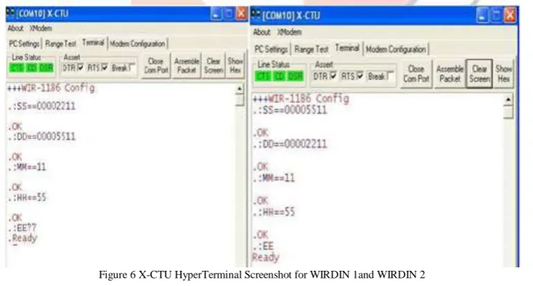
III.WIRDIN1186WIRELESSMODULEANDATCOMMAND
The WIRDIN-1186 module is a low-power wireless communication solution that is ideal for Smart Grid, home automation, smart lighting, industrial sensor data acquisition and remote control applications. This module integrates SPIRIT1, an extremely low-power sub-GHz transceiver, an MCU for wireless network control and hardware interface, a PCB antenna and matching circuitry. Right out- of-the-box this module supports simple point-to-multipoint serial communication over-the-air. It has a small 24mm x 36mm form-factor-for-easy-integration[1][6].
The WIR-1186 modules supports data-hopping, listen-before-talk with random back-off algorithm, end-to-end acknowledgement system, node addressing, network addressing and packet CRC. Nodes can be configured to enable hopping of data to increase the range of the communication link[12]. The destination node address is configurable to setup an acknowledgement based point-to-point communication. Without setting the destination data will be broadcasted to all nodes on the same network address[6].
Figure 6 X-CTU HyperTerminal Screenshot for WIRDIN 1and WIRDIN 2
Figure 7 Arduino Uno with WIRDIN module
IV. SERIAL LCD AND 4X3 KEYPAD
IJEDR1602303
International Journal of Engineering Development and Research (www.ijedr.org)1714
Figure 8 Arduino Uno with serial LCD and keypadV. MATLAB SERIAL COMMUNICATION AND GRAPHICAL USER INTERFACE
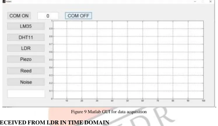
As discussed earlier sensor panel send information (from sensors) serially to the control room via WIRDIN 1186 module. For data acquisition purpose graphical user interface is made in MATLAB (Fig. 9). Communication mode is serial, so a serial object is created in MATLAB[6]. Particular Sensor can be selected from the Popup Menu. Two push buttons are there to connect and disconnect the system with control room. A sensor panel data can be observed in the GUI. User can select any sensor for data acquisition. The graph shows the data acquisition in time domain[7][12][18].
. Figure 9 Matlab GUI for data acquisition
VI.RESPONSERECEIVEDFROMLDRINTIMEDOMAIN
For data acquisition samples have been taken at every 1 sec or 1 Hz. After completion of data acquisition, the time domain equation can be found from the graph.
The resistance of the Light Dependent Resistor (LDR) varies according to the amount of light that falls on it. As discussed earlier Arduino has 10 bit Analog to digital converter (ADC). 210 is equal to 1024[19]. This value can provide us the output voltage Vo. Fig.10 shows the real time data acquisition of LDR.
IJEDR1602303
International Journal of Engineering Development and Research (www.ijedr.org)1715
Figure 11 Response of DHT11 in time domainVIII.RESPONSE RECEIVED FROMREED SWITCHIN TIMEDOMAIN
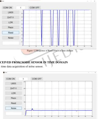
Fig.12shows the real time data acquisition of Reed switch. If there exists magnetic interference than the switch is on else it is off.
Figure 12 Response of Reed switch in time domain
VIII.RESPONSE RECEIVED FROM NOISE SENSOR IN TIME DOMAIN
Fig.13shows the real time data acquisition of noise sensor.
IJEDR1602303
International Journal of Engineering Development and Research (www.ijedr.org)1716
IX.CONCLUSIONAt the end it can be concluded that, a low cost multichannel wireless data acquisition system can be designed, developed and gather the information from environment. This system could be useful in agriculture, defense, manufacturing industries, and many more. Control room is only plotting there real time data. In future wireless dynamic response also can be found using for each and every system using this approach.
REFERENCES
[1] B. Gajjar and S. Sheth, "Design and Automation in Back Plug Press Fitting Process of Ball Pen Assembly", Applied Mechanics and Materials 2014 592: 2596-2600.
[2] B. Gajjar and S. Sheth, "Investigation of Automation Strategy and Its effect on Assembly Cost: A Case Study on Ball Pen Assembly Line", International Journal of Current Engineering and Technology. Special Issue-3: 89-92, 2014
[3] S. Bhavsar and P. Parikh, "Actuation of hydraulic and Pneumatic system using DTMF technology", Proceedings of International Conference on Innovations in Automation and Mechatronics Engineering, G.H. Patel college of engineering and technology, India, pp:184-190.
[4] P. Parikh, K.Joshi and S.Sheth, "Color Guided Vehicle-An Intelligent Material Handling Mechatronic System", Proceedings of the 1st International and 16th National Conference on Machines and Mechanisms (iNaCoMM2013), IIT Roorkee, India, 2013, pp: 628-635.
[5] P. Parikh, H. Shah and S. Sheth, "A Mechatronics design of a line tracker robot using Ziegler Nichols control technique for P, PI and PID controllers", In: International Mechanical Engineering Congress (IMEC-2014), NIT Trichy, India, 2014, DOI: 10.13140/RG.2.1.4107.4722
[6] P. Parikh, H. Shah and S. Sheth, "Development of a multi-channel wireless data acquisition System for swarm robots - A Mechatronic Approach using Arduino UNO and MATLAB", International Journal of Engineering Development and Research (IJEDR), 2014, 2(1): 717-725.
[7] T. Patel, S. Sheth and P. Patel, "Design of Semi-automatic Hydraulic Blanking Machine using PLC", In: National Conference on Innovative & Emerging Technologies (NCIET- 2015), 2015, pp. 410-412. DOI: 10.13140/RG.2.1.4529.6803
[8] S. Sheth, R. Kher, R. Shah, P. Dudhat and P. Jani, "Automatic Sorting System using Machine Vision", In: Multi-Disciplinary International Symposium on Control, Automation & Robotics, 2010, DOI: 10.13140/2.1.1432.1448
[9] Arduino with Matlab Interfacing. http://www.arduino.cc. Date accessed: 2/6/2014
[10]K. Tamboli, S. Sheth, V. Shah, V. Modi, Gandhi and N. Amin, "Design and Development of a Mechatronic System for the Measurement of Railway Tracks", Discovery, 2015, 43 (200): 174-180.
[11]M. Virani, J. Vekariya, S. Sheth and K. Tamboli, "Design and Development of Automatic Stirrup Bending Mechanism", Proceedings of 1st International and 16th National Conference on Machines and Mechanisms (iNaCoMM2013), IIT Roorkee, India, 2013. pp. 598-606.
[12]W. Aung, "Analysis on Modelling and Simulink of DC Motor and Its Driving System Used for Wheeled Mobile Robot", World Academy of Science, Engineering and Technology, 2007, 32: 299-306.
[13]P. Parikh, S. Sheth and T. Patel, "Positional Analysis of a DC brushed Encoder Motor using Ziegler-Nichols Algorithm", CAD/CAM, Robotics and Factories of the Future. Springer India, 2016, pp. 637-650.
[14] 47:1 Metal gear motor, 25DX52L mm with 48 CPR encoder. http://www.pololu.com/.Pololu Robotics and Electronics. Date accessed: 25/12/2015
[15]S. Desai and S. Sheth, "Proposed Design of Centrifugal Casting Machine for Manufacturing of Turbine Bearing", In: National Conference on Advances and Challenges in Engineering and Science (NCACES-2012), L. C. Institute Of Technology, Bhandu, Mehsana, India, 2012, DOI: 10.13140/RG.2.1.4529.2645
[16]S. Desai, S. Sheth and P. Chauhan, "Design and Modelling of Dual faceplate Centrifugal casting equipment for manufacturing of turbine bearing", CAD/CAM, Robotics and Factories of the Future. Springer India, 2016, pp. 523-534. [17]S. Sheth, K. Patel and H. Patel, "Design of Automatic Fuel Filling system using a mechatronics approach", CAD/CAM,
Robotics and Factories of the Future. Springer India, 2106. pp. 785- 795.
[18]P. Parikh, S. Sheth and T. Patel (2016)," Positional Analysis of a DC Brushed Encoder Motor Using Ziegler-Nichols
Algorith", CAD/CAM, Robotics and Factories of the Future (pp. 637-650). Springer India.
[19]S. Maheriya, C. Smeeta and P. Priyam, "A Review: Modeling of Brushed DC Motor and Various type of Control