International Journal of Research (IJR)
e-ISSN: 2348-6848, p- ISSN: 2348-795X Volume 2, Issue 10, October 2015Available at http://internationaljournalofresearch.org
Implementation of Active Type SFCL for Hybrid
Renewable Energy Sources Based DG for Reduction of
Fault Current and Over Voltage
Venkata Anjani kumar G
M-tech Student Scholar Department of EEE, Guntur Engineering College, Guntur (Dt); A.P, India.
[email protected]
P.Suman Pramodkumar
M.Tech
Associate Professor Department of EEE, Guntur Engineering College, Guntur (Dt); A.P, India.
[email protected]
Abstract:
The use of the renewable sources increasingly, application of the distributed generation (DG) in the distribution system acquired more attention. The DG systems are powered by micro sources such as fuel cells, photovoltaic (PV) systems, and wind base systems. PV distributed system in which the solar source is low dc input voltage interfaced to grid using front-end conversion. Wind energy has been recognized as important renewable energy resources because it is clean, abundant and pollution free for the application of distributed generation (DG). In this paper Hybrid system both PV cell and wind energy used as source to the converter. Distributed Generation Resources are increasingly used in distribution systems due to their great advantages. The presence of DG, however, can cause various problems such as miss-coordination, false tripping, blinding and reduction of reach of protective devices. Using superconducting fault current limiters (SFCLs) is one of the best methods to minimize these problems comparing to the other conventional methods. The active SFCL can as well suppress the short-circuit current induced by a three-phase grounded fault effectively, and the power system’s safety and reliability can be improved and it is composed of an air-core superconducting transformer and a PWM converter. The magnetic field in the air-core can be controlled by adjusting the converters output current, and then the active SFCLs equivalent impedance can be regulated for current limitation and possible overvoltage suppression. During the study process, in view of the changes in the locations of the DG units connected to the system, the DG units injection capacities and the fault positions, the active SFCLs
current-limiting and over voltages suppressing characteristics are presented by using Matlab/Simulink software.
Keywords: Resistive type SFCL; Active type SFCL; Distribution generation; over voltages; Fault conditions
I. INTRODUCTION
Compared with conventional approaches towards re-establishing an effective and selective protection scheme, such as replacing the existing circuit breakers, altering the original relay setting or disconnecting DG from the distribution network during faults, installing a Fault Current Limiter (FCL) in series with DG unit is increasingly considered to be a potentially more economical, efficient and reliable solution. Voltage stability is another task for distribution network during faults. The increasing fault current leads to voltage sags at feeder neighboring the faulty ones, potentially causing power instability. Besides, for DGs connected to the utility, since their output voltage and frequency are determined by the system AC source, they become very sensitive to external disturbance, which can cause unnecessary disconnections in certain circumstances. Losing connection of large number of DGs may lead to sudden appearance of hidden loads, previously locally supplied by the DG, and impact the voltage profile. A lot of efforts have been done to find solutions to the voltage stability issue in the past.
International Journal of Research (IJR)
e-ISSN: 2348-6848, p- ISSN: 2348-795X Volume 2, Issue 10, October 2015Available at http://internationaljournalofresearch.org
(SFCL), Electromagnetic FCL (EMFCL) based on impedance insertion, and Solid-state FCL (SSFCL) based on switching action. Compared with other types of FCL, the SFCL has the advantages of being self-triggering, fast responding and self-recovering. Due to these favorable features the SFCL is selected for being analyzed for its potential contribution to solving the above-mentioned DG-related problems. Additionally, this research aims at developing a new topology of SFCL with better performance compared with currently existing topologies. The most significant feature of the new topology is short recovery time, so that it can be coordinated with automatic re-closers. The integration of renewable energy sources into electric power distribution systems can provide additional economic benefits because of a reduction in the losses associated with transmission and distribution lines. In this work a SFCL model is designed. SFCL is an innovative fault current limiter. It works on the principle of Superconducting Property. It is inactive under normal condition. It is in active under fault condition; it inserts some resistance into the line to limit the fault current. It suppresses the fault current within first half cycle only. It operates better than Circuit breakers, Relays, because the Circuit breaker takes minimum 2-3 cycles before they getting activated. The effect of SFCL on micro grid fault current observed. The optimal place to SFCL is determined.
Due to increased consumption demand and high cost of natural gas and oil, distributed generation (DG), which generates electricity from many small energy sources, is becoming one of main components in distribution systems to feed electrical loads [1]–[2]. The introduction of DG into a distribution network may bring lots of advantages, such as emergency backup and peak shaving. However, the presence of these sources will lead the distribution network to lose its radial nature, and the fault current level will increase. Besides, when a single-phase grounded fault happens in a distribution system with isolated neutral, over voltages will be induced on the other two health phases, and in consideration of the installation of multiple DG units, the impacts of the induced over voltages on the distribution network’s insulation stability and operation safety should be taken into account seriously. Aiming at the mentioned technical problems, applying superconducting fault current limiter (SFCL) may be a feasible solution.
II. ANALYSIS OF ACTIVE TYPE AND RESISTIVE TYPE SFCL
A. Structure and Principle of the Active SFCL
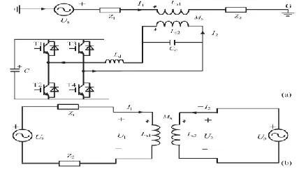
As shown in Fig. 1(a), it denotes the circuit structure of the single-phase voltage compensation type active SFCL, which is composed of an air-core superconducting transformer and a voltage-type PWM converter. Ls1, Ls2 are the self-inductance of two superconducting windings, and Ms is the mutual inductance. Z1 is the circuit impedance and Z2 is the load impedance. Ld and Cd are used for filtering high order harmonics caused by the converter. Since the voltage-type converter’s capability of controlling power exchange is implemented by regulating the voltage of AC side, the converter can be thought as a controlled voltage source Up. By neglecting the losses of the transformer, the active SFCL’s equivalent circuit is shown in Fig. 1(b).
Fig. 1. Single-phase voltage compensation type active SFCL. (a) Circuit structure and (b) equivalent circuit.
In normal (no fault) state, the injected current (I2) in the secondary winding of the transformer will be controlled to keep a certain value, where the magnetic field in the air-core can be compensated to zero, so the active SFCL will have no influence on the main circuit. When the fault is detected, the injected current will be timely adjusted in amplitude or phase angle, so as to control the superconducting transformer’s primary voltage which is in series with the main circuit, and further the fault current can be suppressed to some extent. Below, the suggested SFCL’s specific regulating mode is explained. In normal state, the two equations can be achieved.
(1)
International Journal of Research (IJR)
e-ISSN: 2348-6848, p- ISSN: 2348-795X Volume 2, Issue 10, October 2015Available at http://internationaljournalofresearch.org
Controlling I2 to make jωLs1 I˙1 − jωMs I˙2 = 0 and the primary voltage U1 will be regulated to zero. Thereby, the equivalent limiting impedance ZSFCL is zero (ZSFCL = U1/I1), and I2 can be set as ˙ I2 = ˙Us_Ls1/Ls2/ (Z1 + Z2) k, where k is the coupling coefficient and it can be shown as k = Ms/√Ls1Ls2.Under fault condition (Z2 is shorted), the main current will rise from I1 to I1f, and the primary voltage will increase to U1f.
(3)
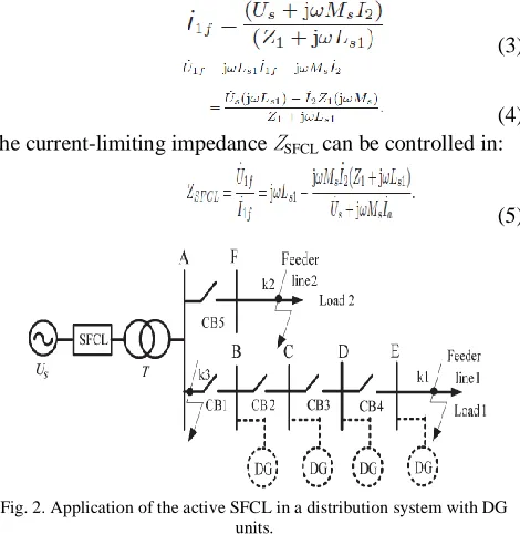
(4) The current-limiting impedance ZSFCLcan be controlled in:
(5)
Fig. 2. Application of the active SFCL in a distribution system with DG units.
According to the difference in the regulating objectives of I2, there are three operation modes:
1) Making I2 remain the original state, and the limiting impedance ZSFCL−1 = Z2 (jωLs1)/ (Z1 + Z2 + jωLs1).
2) Controlling I2 to zero, and ZSFCL−2 = jωLs1.
3) Regulating the phase angle of I2 to make the angle difference between ˙Us and jωMs I˙2 be 180◦. By setting jωMs ˙ I2 = −c ˙Us, and ZSFCL−3 = cZ1/(1 − c) + jωLs1/(1 − c).
The air-core superconducting transformer has many merits, such as absence of iron losses and magnetic saturation, and it has more possibility of reduction in size, weight and harmonic than the conventional iron-core superconducting transformer. Compared to the iron-core, the air-core can be more suitable for functioning as a shunt reactor because of the large magnetizing current and it can also be applied in an inductive pulsed power supply to decrease energy loss for larger pulsed current and higher energy transfer efficiency.
There is no existence of transformer saturation in the air-core, and using it can ensure the linearity of ZSFCL well.
B. Applying the SFCL into a Distribution Network with DG
As shown in Fig. 2, it indicates the application of the active SFCL in a distribution network with multiple DG units, and the buses B-E are the DG units’ probable installation locations. When a single-phase grounded fault occurs in the feeder line 1 (phase A, k1 point), the SFCL’s mode 1 can be automatically triggered, and the fault current’s rising rate can be timely controlled. Along with the mode switching, its amplitude can be limited further. In consideration of the SFCL’s effects on the induced overvoltage, the qualitative analysis is presented.
In order to calculate the over voltages induced in the other two phases (phase B and phase C), the symmetrical component method and complex sequence networks can be used, and the coefficient of grounding G under this condition can be expressed as G = −1.5m/(2 + m) ± j √ 3/2,
where m = X0/X1, and X0 is the distribution network’s zero-sequence reactance, X1 is the positive-sequence reactance. Further, the amplitudes of the B-phase and C-phase over voltages can be described as:
(6) Where UAN is the phase-to-ground voltage’s root mean square (RMS) under normal condition. As shown in Fig. 3, it signifies the relationship between the reactance ratio m and the B-phase overvoltage. It should be pointed out that, for the distribution system with isolated neutral-point, the reactance ratio m is usually larger than four. Compared with the condition without SFCL, the introduction of the active SFCL will increase the power distribution network’s positive-sequence reactance under fault state. Since X0/(X1 + ZSFCL) < X0/X1, installing the active SFCL can help to reduce the ratio m. And then, from the point of the view of applying this suggested device, it can lower the overvoltage’s amplitude and improve the system’s safety and reliability.
Furthermore, taking into account the changes in the locations of the DG units connected into the distribution system, the DG units’ injection capacities and the fault positions, the specific effects of the SFCL on the fault current and overvoltage may be different, and they are all imitated in the simulation analysis.
C. Structure of Resistive-SFCL
International Journal of Research (IJR)
e-ISSN: 2348-6848, p- ISSN: 2348-795X Volume 2, Issue 10, October 2015Available at http://internationaljournalofresearch.org
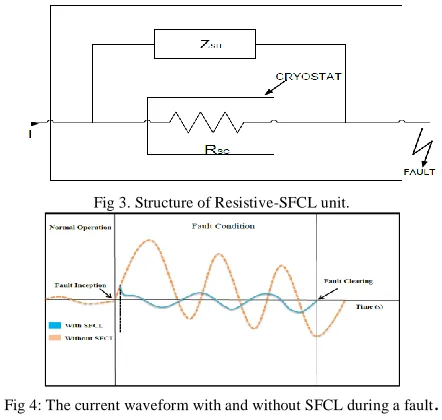
Superconducting to Normal (S/N) state transition .The resistive type SFCLs is shown in series with the source and load (Fig.3). During normal operation the current flowing through the superconducting element RSC dissipates low energy. If the current rise above the critical current value the resistance RSC increases rapidly. The dissipated losses due to the rapid raise in resistance heats the superconductor above the critical temperature Tc and the superconductor RSC changes its state from superconducting to Normal state and fault current is reduced instantaneously. This phenomenon is called quench of superconductors. When the fault current has been reduced, the element RSC recovers its superconducting state. The parallel resistance or inductive shunt ZSH is needed to avoid hot spots during quench, to adjust the limiting current and to avoid over-voltages due to the fast current limitations. The resistive SFCLs are much smaller and lighter than the inductive ones. They are vulnerable to excessive heat during the quench state.
Fig 3. Structure of Resistive-SFCL unit.
Fig 4: The current waveform with and without SFCL during a fault
.
III. PHOTOVOLTAIC (PV) SYSTEMIn the crystalline silicon PV module, the complex physics of the PV cell can be represented by the equivalent electrical circuit shown in Fig. 5. For that equivalent circuit, a set of equations have been derived, based on standard theory, which allows the operation of a single solar cell to be simulated using data from manufacturers or field experiments.
Fig.5 Equivalent electrical circuit of a PV module.
The series resistance RS represents the internal losses due to the current flow. Shunt resistance Rsh, in parallel with diode, this corresponds to the leakage current to the ground. The single exponential equation which models a PV cell is extracted from the physics of the PN junction and is widely agreed as echoing the behavior of the PV cell
(10)
The number of PV modules connected in parallel and series in PV array are used in expression. The Vt is also defined in terms of the ideality factor of PN junction (n), Boltzmann’s constant (KB), temperature of photovoltaic array (T), and the electron charge (q). Applied a dynamical electrical array reconfiguration (EAR) strategy on the photovoltaic (PV) generator of a grid-connected PV system based on a plant-oriented configuration, in order to improve its energy production when the operating conditions of the solar panels are different. The EAR strategy is carried out by inserting a controllable switching matrix between the PV generator and the central inverter, which allows the electrical reconnection of the available PV modules.
IV .WIND ENERGY BASED SYSTEM
Wind is abundant almost in any part of the world. Its existence in nature caused by uneven heating on the surface of the earth as well as the earth’s rotation means that the wind resources will always be available. The conventional ways of generating electricity using non renewable resources such as coal, natural gas, oil and so on, have great impacts on the environment as it contributes vast quantities of carbon dioxide to the earth’s atmosphere which in turn will cause the temperature of the earth’s surface to increase, known as the green house effect. Hence, with the advances in science and technology, ways of generating electricity using renewable energy resources such as the wind are developed. Nowadays, the cost of wind power that is connected to the grid is as cheap as the cost of generating electricity using coal and oil. Thus, the increasing popularity of green electricity means the demand of electricity produced by using non renewable energy is also increased accordingly.
International Journal of Research (IJR)
e-ISSN: 2348-6848, p- ISSN: 2348-795X Volume 2, Issue 10, October 2015Available at http://internationaljournalofresearch.org
The major components of a typical wind energy conversion system include a wind turbine, generator, interconnection apparatus and control systems, as shown in Figure 6. Wind turbines can be classified into the vertical axis type and the horizontal axis type. Most modern wind turbines use a horizontal axis configuration with two or three blades, operating either down-wind or up-wind. A wind tur-bine can be designed for a constant speed or variable speed operationgenerator is coupled to the rotor of a wind turbine directly, offers high reliability, low maintenance, and possibly low cost for certain turbines , power electronic converters to provide a fixed frequency and fixed voltage power to their loads.
V. MATLAB/SIMULINK RESULTS
Matlab/Simulink results of this paper shown in below figures.7.to16
Fig.7.Matlab/Simulink Model of Proposed Distribution System with Distributed Generation Units without any compensation scheme using
Active SFCL methodology, using Matlab/Simulink platform.
Fig.8. Voltage characteristics (Bus voltages Vs time ) of the Bus-under
different locations of DG without SFCL.
Fig.9. Voltage characteristics (Bus voltages Vs time )of the Bus-A under different locations of DG with SFCL.
Fig.10. Line current waveforms (Line current Vs time)when the three-phase short-circuit occur at k3 point without SFCL
International Journal of Research (IJR)
e-ISSN: 2348-6848, p- ISSN: 2348-795X Volume 2, Issue 10, October 2015Available at http://internationaljournalofresearch.org
Fig.12. Active SFCL’s current-limiting performances (Line current Vs time) under different fault locations at k1point.
Fig.13. Active SFCL’s current-limiting performances .(Line current Vs time) under different fault locations at k2 point.
Fig.14.DG System with Hybrid Renewable Energy Sources.
Fig.15.Matlab/Simulink Model of Proposed Distribution System with Hybrid Energy (wind and PV cell) Generation based Distributed Generation Units scheme using Active SFCL methodology, using Matlab/Simulink platform.
Fig.16.Voltage characteristics (Bus voltages Vs time ) of the Bus-A under different locations of DG with SFCL operated under DG mode by using wind energy and PV scheme.
VI.CONCLUSION
International Journal of Research (IJR)
e-ISSN: 2348-6848, p- ISSN: 2348-795X Volume 2, Issue 10, October 2015Available at http://internationaljournalofresearch.org
energy sources and the SFCL becomes very meaningful, and it will be performed in future.
REFERENCES
[1] S. Conti, “Analysis of distribution network protection issues in presence of dispersed generation,” Elect. Power Syst. Res., vol. 79, no. 1, pp. 49–56, Jan. 2009.
[2] S.-Y. Kim and J.-O. Kim, “Reliability evaluation of distribution network with DG considering the reliability of protective devices affected by SFCL,” IEEE Trans. Appl. Supercond., vol. 21, no. 5, pp. 3561–3569, Oct. 2011.
[3] S. A. A. Shahriari, A. Yazdian, and M. R. Haghifam, “Fault current limiter allocation and sizing in distribution system in presence of distributed generation,” in Proc. IEEE Power Energy Soc. Gen. Meet., Calgary, AB, Canada, Jul. 2009, pp. 1–6.
[4] S.-H. Lim, J.-S. Kim, M.-H. Kim, and J.-C. Kim, “Improvement of protection coordination of protective devices through application of a SFCL in a power distribution system with a dispersed generation,” IEEE Trans. Appl. Supercond., vol. 22, no. 3, p. 5601004, Jun. 2012.
[5] L. Chen, Y. Tang, J. Shi, and Z. Sun, “Simulations and experimental analyses of the active superconducting fault current limiter,” Phys. C, vol. 459, no. 1/2, pp. 27–32, Aug. 2007.
[6] L. Chen, Y. Tang, J. Shi, Z. Li, L. Ren, and S. Cheng, “Control strategy for three-phase four-wire PWM converter of integrated voltage compensation type active SFCL,” Phys. C, vol. 470, no. 3, pp. 231– 235, Feb. 2010.
[7] L. Chen, Y. J. Tang, J. Shi, L. Ren, M. Song, S. J. Cheng, Y. Hu, and X. S. Chen, “Effects of a voltage compensation type active superconducting fault current limiter on distance relay protection,” Phys. C, vol. 470, no. 20, pp. 1662–1665, Nov. 2010.
[8] J. Wang, L. Zhou, J. Shi, and Y. Tang, “Experimental investigation of an active superconducting current controller,” IEEE Trans. Appl. Supercond., vol. 21, no. 3, pp. 1258–1262, Jun. 2011.
[9] M. Song, Y. Tang, N. Chen, Z. Li, and Y. Zhou,
“Theoretical analy-sis and experiment research of high temperature superconducting air-core transformer,” in
Proc. Int. Conf. Electr. Mach. Syst., Wuhan, China,
Oct. 2008, pp. 4394–4397
[10] R. Wu, Y. Wang, Z. Yan, W. Luo, and Z. Gui, “Design and experimental realization of a new pulsed power supply based on the energy transfer between two capacitors and an HTS air-core pulsed
transformer,” IEEETrans. Plasma Sci., vol. 41, no. 4,
pp. 993–998, Apr. 2013
[11] S. Chen, W. Wang, and P. Yang, “Effects of current-limiting inductor on power frequency
overvoltages in transmission line,” Power Syst.
Technol., vol. 34, no. 3, pp. 193–196, Mar. 2010
[12] H. Yamaguchi and T. Kataoka, “Stability
analysis of air-core supercon-ducting power
transformer,” IEEE Trans. Appl. Supercond., vol. 7,
no. 2, pp. 1013–1016, Jun. 1997
Venkata anjanikumar. G was born in nellore,AndhraPradesh,India.He received his B.Tech Degree in Electrical and Electronics Engineering from PBR visvodaya institute of science and technology, kavali,nellore,A.P. India. Presently, he is pursuing M.Tech (Power systems) at Guntur Engineering College, Guntur India. His current research interest includes Electrical Machines and Power system, power electronics.