Comparative Analysis of Fast Acting AVR
and ALFC Loops with Classical Controllers
on Dynamic Stability Improvement
Dr.Venu Yarlagadda
1, P.Sai Saroja
2, P.Avinash
3, P.Nikhilesh
4Associate Professor, Dept. of EEE, VNR VJIET, Hyderabad, Telangana, India 1
Students, Dept. of EEE, VNR VJIET, Hyderabad, Telangana, India 234
ABSTRACT: The dynamic stability of the Synchronous Generator have been improved using fast acting combined Automatic Voltage Regulator (AVR) and Automatic Load Frequency Control (ALFC) loops. This paper investigates the effect of Fast acting AVR and ALFC loops on the dynamic stability improvement and its comparison with the conventional controller‟s viz. PD and PID Controllers.The combined linearised AVR and ALFC model has been simulated in Matlab/Simulink in three cases. Case1 with slow, medium and fast acting loops. Case2 with slow acting loops with PD and PID Controllers and case3 with Medium fast acting loops with controllers. The block diagram of Automatic load frequency control (ALFC) of an isolated power system (obtained by combining the individual blocks of generator, load, prime mover model and speed governing system) is combined with Automatic Voltage Regulator(AVR) is simulated without any controller for three different cases viz. Slow, Medium and fast time constants of both the loops. In case2 the test system is simulated with conventional controllers (PD and PID) and in case3 the system is simulated with medium fast acting loops in addition to conventional controllers (PD and PID).The frequency deviation step response and terminal voltage step response have been obtained for all cases. The paper compares the performance of all the methods on dynamic stability improvement
KEYWORDS: AVR Control, ALFC Control, Combined AVR and ALFC loops, Dynamic Stability, Stability Improvement using Fast acting controllers and Steam Power Station Stability Analysis.
I.INTRODUCTION I.A. Literature Survey
H.D. Mathur and S.Ghosh proposed fuzzy approach for determining the optimal values for the proportional-integral(PI) controller parameters of load frequency control(LFC) Automatic voltage regulator(AVR) system for single area power system using the Fuzzy Gain Scheduled proportional-integral controller (FGSPIC) techniques in IEEE Power India conference.D.M.Vinod Kumar proposed Evolutionary Algorithms (EA) like, Enhanced Particle Swarm Optimization (EPSO), Multi Objective Particle Swarm Optimization (MOPSO), and Stochastic Particle Swarm Optimization (SPSO to overcome the premature convergence problem in a standard PSO. Simulation results demonstrate that the proposed controller adapt themselves appropriate to varying loads and hence provide better performance characteristics with respect to settling time, oscillations and overshoot. In the Proc. of IEEE region 10 International conference on global connectivity in Energy, Computer, Communication and Control, 1998, pp557-574.
T R Shyama, R Satheesh Kumar, V Shanmugasundaram have proposed to show the interaction between the LFC and the AVR loops. The system with its control method is going to implement in MATLAB software. Also, a conventional proportional and integral (PI) controller was used to control the same for the performance comparison. T wo performance criteria were utilized for the comparison. The proposed method had superior features like, stable convergence characteristics, easy implementation and good computational efficiency.
I.B. General Introduction to proposed work
the real power balance; as well as the reactive power balance is to be achieved. There are two basic control mechanisms used to achieve reactive power balance (acceptable voltage profile) and real power balance (acceptable frequency values). The former is called the automatic voltage regulator (AVR) and the latter is called the automatic load frequency control (ALFC) or automatic generation control (AGC).
In this paper the dynamic stability analysis of a steam power station using Matlab/Simulink models have been studied. The combined fast acting Automatic load frequency control (ALFC) and Automatic voltage regulator (AVR) control loops have been simulated in SIMULINK. The load frequency loop controls the real power and frequency and the automatic voltage regulator loop regulates the reactive power and voltage magnitude. The excitation system time constant is much smaller than prime mover time constant and it‟s transients decay much faster and does not effect the ALFC dynamics. The cross coupling between the LFC loop and the AVR loop is negligible and the load frequency and excitation voltage control are analysed independently and its simulation responses are obtained
The MATLAB/SIMULINK Models have been developed to study the dynamic stability analysis of the system. The simulation response of combined ALFC and AVR loops without any controllers for slow, medium and fast has been studied. Secondly the same system is simulated with PD and PID controllers. The test results have been compared Fast acting loops with that of PD and PID controllers.
II. POWER SYSTEM STABILITY
Successful operation of a power system depends largely on the engineer's ability to provide reliable and uninterrupted service to the loads. The reliability of the power supply implies much more than merely being available. Ideally, the loads must be fed at constant voltage and frequency at all times. In practical terms this means that both voltage and frequency must be held within close tolerances so that the consumers‟ equipment may operate satisfactorily.
II.A. Classification of Stability
Power System Stability is broadly classified into two categories one is Generator Stability or Rotor angle Stability and the other is Voltage Stability. Angular stability is basically generator stability while voltage stability means load stability. Rotor angle stability is mainly interlinked to real power transfer whereas voltage stability is related to reactive power.
II.B. Generator or Synchronous or Rotor angle Stability
The stability problem is concerned with the behaviour of the synchronous machines after they have been perturbed. If the perturbation does not involve any net change in power, the machines should return to their original state. If an unbalance between the supply and demand is created by a change in load, in generation, or in network conditions, a new operating state is necessary. In any case all interconnected synchronous machines should remain in synchronism if the system is stable; i.e., they should all remain operating in parallel and at the same speed.
The stability of an interconnected power system is its ability to return to its normal or stable operation after having been subjected to some form of disturbance. The tendency of synchronous machine to develop forces so as to maintain synchronism and equilibrium is called stability. The stability limit represents the maximum stead state power flow possible when the synchronous machine is operating with stability.
There are three forms of stability.
Steady state stability Transient stability
Dynamic Stability
II.C. Voltage Stability
Voltage stability refers to „„the ability of a power system to maintain steady voltages at all buses in the system after being subjected to a disturbance from a given initial operating condition‟‟. If voltage stability exists, the voltage and power of the system will be controllable at all times. In general, the inability of the system to supply the required demand leads to voltage instability (voltage collapse).
II.D. Stability Improvement Methods
Methods to improve stability are:
1. Use of double circuit lines
3. Series compensation of the lines
4. High speed excitation systems
5. HVDC links
6. Load shedding
7. Using the quick response system
III.LOADFREQUENCYCONTROLOFANISOLATEDPOWERSYSTEM
The operating objectives of the Load Frequency Control (LFC) are to maintain reasonably uniform frequency to divide the load between generators, and to control tie-line interchange schedules. The change in frequency and tie-line power are sensed, which is a measure of the change in rotor angle δ, i.e the error Δδ to be corrected. The error signal, i.e., Δf and ΔPtie, are amplified, mixed, and transformed into a real power signal ΔP, which is sent to the prime mover to call
for an increment in the torque. The prime mover therefore brings change in the generator output by an output ΔPg
which will change the values of Δf and ΔPtie with the specified tolerance.
The system load changes continuously, the generation are adjusted automatically to restore the frequency to the nominal value. The scheme is known as the automatic generation control. In an inter connected system consisting of several loops, the role of AGC is to divide the loads among system, station, and generators so as to achieve maximum economy and correctly control the scheduled interchanges of tie-line power while maintaining a reasonably uniform frequency.
The ALFC is to control the frequency deviation by maintaining the real power balance in the system. The main functions of the ALFC are to i) to maintain the steady frequency; ii) control the tie-line flows; and iii) distribute the load among the participating generating units. The control (input) signals are the tie-line deviation ∆Ptie (measured from the tie- line flows), and the frequency deviation ∆f (obtained by measuring the angle deviation ∆δ). These error signals ∆f and ∆Ptie are amplified, mixed and transformed to a real power signal, which then controls the valve position. Depending on the valve position, the turbine (prime mover) changes its output power to establish the real power balance.
The load on the system is composite consisting of a frequency independent component and a frequency dependent component. The load can be written as ∆Pe=∆P0+∆Pf where, ∆Pe is the change in the load; ∆P0 is the frequency independent load component; ∆Pf is the frequency dependent load component. ∆Pf = D∆ω where, D is called frequency characteristic of the load (also called as damping constant) expressed in percent change in load for 1% change in frequency. If D=1.5%, then a 1% change in frequency causes 1.5% change in load, the Automatic Load Frequency Control Loop i.e. ALFC loop as shown in Figure.1.below.
With the primary LFC loop, a change in the system load will result in a steady-state frequency deviation depending on the governor speed Regulation. In order to reduce the frequency deviation to 0, a reset action is provided by introducing an integral controller to act on the load reference setting to change the speed set point. The Block Diagram Model of ALFC Loop simulated in MATLAB/SIMULINK as shown in Fig.2 below.
Fig.2 MATLAB / SIMULINK Model of ALFC Loop
IV. AUTOMATIC VOLTAGE REGULATOR
The voltage of the generator is proportional to the speed and excitation (flux) of the generator. The speed being constant, the excitation is used to control the voltage. Therefore, the voltage control system is also called as excitation control system or automatic voltage regulator (AVR).For the alternators, the excitation is provided by a device (another machine or a static device) called exciter. For a large alternator the exciter may be required to supply a field current of as large as 6500A at 500V and hence the exciter is a fairly large machine. Depending on the way the dc supply is given to the field winding of the alternator (which is on the rotor), the exciters are classified as: i) DC Exciters; ii) AC Exciters; and iii) Static Exciters. Accordingly, several standard block diagrams are developed by the IEEE working group to represent the excitation system. A schematic of an excitation control system is shown in Figure.3 below.
The stabilizing compensator shown i n f i g . 4 i s used to improve the dynamic response of the exciter. The input to this block is the exciter voltage and the output is a stabilizing feedback signal to reduce the excessive overshoot.
Fig.4 Block Diagram Model of AVR Loop
A change in the real power demand effects essentially the frequency, whereas a change in the reactive power affects mainly the voltage magnitude. The interaction between voltage and frequency controls is generally weak enough to justify their analysis separately. The sources of reactive power are generators, capacitors, Synchronous Condensers and FACTS Controllers. The generator reactive power is controlled by field excitation. The primary means of generator reactive power control is generator excitation control using automatic voltage regulator (AVR) is to hold the terminal voltage magnitude of a synchronous generator at desired level. The Block Diagram Model of AVR Loop simulated in MATLAB/SIMULINK as shown in Fig.5 below.
Fig.5 Simulink Model of AVR Loop
V. COMBINED ALFC AND AVR LOOPS
excitation system time constant is much smaller than the prime mover time constant and its transient decay much faster than and does not affect the LFC dynamic. Thus the cross coupling between the LFC loop and the AVR loop is negligible, and the load frequency and excitation voltage control are analyzed interpedently. The schematic diagram of Combined ALFC and AVR loops as shown in Fig.6 below
Fig.6 Schematic diagram of Combined ALFC and AVR loops
The ALFC loop shown in Figure13 is called the primary ALFC loop. It achieves the primary goal of real power balance by adjusting the turbine output ∆Pm to match the change in load demand ∆PD. All the participating generating units contribute to the change in generation. But a change in load results in a steady state frequency deviation ∆f. The restoration of the frequency to the nominal value requires an additional control loop called the supplementary loop. This objective is met by using integral controller which makes the frequency deviation zero. The ALFC with the supplementary loop is generally called the AGC. The main objectives of AGC a r e i) to regulate t h e frequency (using both primary and supplementary controls); ii) and to maintain the scheduled tie-line flows. A secondary objective of the ALFC is to distribute the required change in generation among the connected generating units economically (to obtain least operating costs), as shown in Fig.7 below which is the combined block diagram of ALFC and AVR loops illustrating the fundamental principles of both the controllers.
VI. CASE STUDY AND RESULTS
The test system is simulated using SIMULINK Models in three cases. Case1 with slow, medium and fast acting loops. Case2 with slow acting loops with PD and PID Controllers and case3 with Medium fast acting loops with controllers. The block diagram of Automatic load frequency control (ALFC) of an isolated power system (obtained by combining the individual blocks of generator, load, prime mover model and speed governing system) is combined with Automatic Voltage Regulator(AVR) is simulated without any controller for three different cases viz. Slow, Medium and fast time constants of both the loops. In case2 the test system is simulated with conventional controllers (PD and PID) and in case3 the system is simulated with medium fast acting loops in addition to conventional controllers (PD and PID).The frequency deviation step response and terminal voltage step response have been obtained for all cases. The paper compares the performance of all the methods on dynamic stability improvement
VI.A.Case 1
Case1 with slow (Case1A), medium (Case1B) and fast acting (Case1C) loops presented below. The block diagram of Automatic load frequency control (ALFC) of an isolated power system (obtained by combining the individual blocks of generator, load, prime mover model and speed governing system) is combined with Automatic Voltage Regulator(AVR) is simulated without any controller for three different cases viz. Slow, Medium and fast time constants of both the loops.
VI.A.1.Case 1A
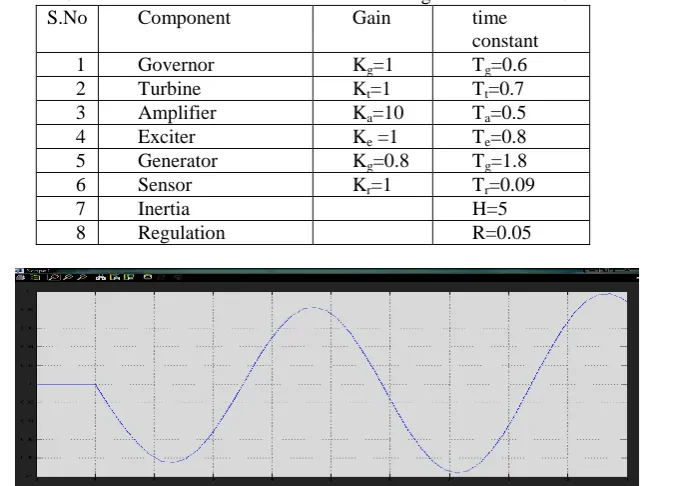
The block diagram of Automatic load frequency control (ALFC) of an isolated power system (obtained by combining the individual blocks of generator, load, prime mover model and speed governing system) is combined with Automatic Voltage Regulator(AVR) is simulated without any controller for three different cases viz. Slow, Medium and fast time constants of both the loops. Fig.8 shows the combined slow acting ALFC and AVR Loops without any controller and Table.1 shows the corresponding gain values and time constants of slow acting combined ALFC and AVR Loops.Fig.9 shows the dynamic response of frequency and Fig.10 shows the corresponding dynamic response of voltage for case 1A.
Table 1. Gain Values and time constants of slow acting combined ALFC and AVR Loops
S.No Component Gain time
constant 1 Governor Kg=1 Tg=0.6
2 Turbine Kt=1 Tt=0.7
3 Amplifier Ka=10 Ta=0.5
4 Exciter Ke =1 Te=0.8
5 Generator Kg=0.8 Tg=1.8
6 Sensor Kr=1 Tr=0.09
7 Inertia H=5
8 Regulation R=0.05
Fig.9 Frequency response of slow acting combined ALFC and AVR loops
Fig.10 Voltage Variation of slow acting combined ALFC and AVR loops
VI.A.2. Case 1B
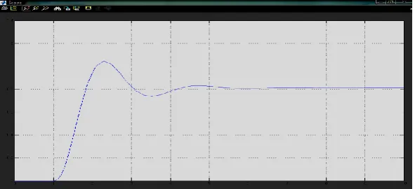
In case1B the test system is simulated with medium fast loops. Table.2 shows the corresponding gain values and time constants of medium fast acting combined ALFC and AVR Loops.Fig.11 shows the dynamic response of frequency and Fig.12 shows the corresponding dynamic response of voltage.
Table 2. Gain Values and time constants of medium fast acting combined ALFC and AVR
S.No Component Gain time
constant 1 Governor Kg=1 Tg=0.4
2 Turbine Kt=1 Tt=0.7
3 Amplifier Ka=10 Ta=0.3
4 Exciter Ke =1 Te=0.6
5 Generator Kg=0.8 Tg=1.6
6 Sensor Kr=1 Tr=0.07
7 Inertia H=5
Fig.11 Frequency response of medium fast acting combined ALFC and AVR loops
Fig.12 Voltage Variation of medium fast acting combined ALFC and AVR loops
VI.A.3 Case 1C
In case 1C the system is simulated with fast acting loops. Table.3 shows the corresponding gain values and time constants of medium fast acting combined ALFC and AVR Loops.Fig.13 shows the dynamic response of frequency and Fig.14 shows the corresponding dynamic response of voltage
Table.3 Gain Values and time constants of fast acting combined ALFC and AVR
S.No Component Gain time
constant 1 Governor Kg=1 Tg=0.2
2 Turbine Kt=1 Tt=0.5
3 Amplifier Ka=10 Ta=0.1
4 Exciter Ke =1 Te=0.4
5 Generator Kg=0.8 Tg=1.4
6 Sensor Kr=1 Tr=0.05
7 Inertia H=5
Fig.13 Frequency response of fast acting combined ALFC and AVR loops
Fig.14 Voltage Variation of fast acting combined ALFC and AVR loops
VI.B.Case 2
Case2 with medium fast acting loops with PD and PID Controllers. The block diagram of Automatic load frequency control (ALFC) of an isolated power system (obtained by combining the individual blocks of generator, load, prime mover model and speed governing system) is combined with Automatic Voltage Regulator(AVR) is simulated without any controller for three different cases viz. Slow, Medium and fast time constants of both the loops. In case2 the test system is simulated with conventional controllers (PD and PID).
VI.B.1 Case 2A
Medium fast acting loops with PD Controller values are shown in Table 4. Corresponding dynamic response of frequency and voltage as shown in fig.15 and fig.16 respectively
Table 4. Gain Values and time constants of medium fast acting loops with PD controller
S.No Component Gain Time
constant 1 Governor Kg=1 Tg=0.4
2 Turbine Kt=1 Tt=0.7
3 Amplifier Ka=10 Ta=0.3
4 Exciter Ke =1 Te=0.6
5 Generator Kg=0.8 Tg=1.6
6 Sensor Kr1=1 T=0.07
7 Inertia H=5
8 Regulation R=0.05
9 Proportion controller Kp=1
10 Integral controller Kt=0.25
Fig.15 Frequency response of medium fast acting loops with PD Controller
Fig.16 Voltage Variation of medium fast acting loops with PD Controller
VI.B.2 Case 2B
Medium fast acting loops with PID Controller values are shown in Table 5, Corresponding dynamic response of frequency and voltage as shown in fig.17 and fig.18 respectively.
Table.5 Gain Values and time constants of medium fast acting loops with PID Controller
S.No Component Gain time
constant 1 Governor Kg=1 Tg=0.4
2 Turbine Kt=1 Tt=0.7
3 Amplifier Ka=10 Ta=0.3
4 Exciter Ke =1 Te=0.6
5 Generator Kg=0.8 Tg=1.6
6 Sensor Kr1=1 T=0.07
7 Inertia H=5
8 Regulation R=0.05
9 Proportion controller Kp=1
10 Integral controller Kt=0.25
Fig.17 Frequency dynamic response of medium fast acting loops with PID Controller
Fig.18 Dynamic response of voltage for medium fast acting loops with PID Controller
VI.B.3 Case 2C
The combined operation of fast acting loops including PID Controller values are shown in Table 6, Corresponding dynamic response of frequency and voltage as shown in fig.19 and fig.20 respectively.
Table.6 Gain Values and time constants of medium fast acting loops with PID Controller
S.No Component Gain time
constant 1 Governor Kg=1 Tg=0.2
2 Turbine Kt=1 Tt=0.5
3 Amplifier Ka=10 Ta=0.1
4 Exciter Ke =1 Te=0.4
5 Generator Kg=0.8 Tg=1.4
6 Sensor Kr=1 T=0.05
7 Inertia H=5
8 Regulation R=0.05
9 Proportion controller Kp=1
10 Integral controller Kt=0.25
Fig.19 Frequency dynamic response of fast acting loops with PID Controller
Fig.20 Dynamic response of voltage for fast acting loops with PID Controller
VII. CONCLUSIONS
The test system is simulated using SIMULINK Models with two different cases. Case1 with slow (Case1A), medium (Case1B) and fast acting (Case1C) loops. Case2 with medium fast acting loops with PD (Case 2A) and PID Controllers (Case 2B) and with fast acting loops along with PID controller (Case 2C). The block diagram of Automatic load frequency control (ALFC) of an isolated power system (obtained by combining the individual blocks of generator, load, prime mover model and speed governing system) is combined with Automatic Voltage Regulator(AVR) is simulated without any controller for three different cases viz. Slow, Medium and fast time constants of both the loops. In case2 the test system is simulated with conventional controllers (PD and PID) simulated with medium fast acting loops and fast acting loops.
The dynamic stability of the system has been improved using fast acting combined Automatic Voltage Regulator (AVR) and Automatic Load Frequency Control (ALFC) loops. By combining fast acting loops with conventional controllers (PID) the dynamic stability is tremendously improved. This paper investigates the effect of Fast acting AVR and ALFC loops on the dynamic stability improvement and its comparison with the conventional controller‟s viz. PD and PID Controllers.
VIII. ACKNOWLEDGEMENTS
We are immensely thankful to Management and Principal of VNR VJIET for providing R&D lab and other facilities to carryout this work.
REFERENCES
[1] H.D. Mathur and S.Ghosh, “A comprehensive analysis of Intelligent control for load frequency control”, IEEE Power India conference, 2006. [2] D.M.Vinod Kumar, “Intelligent Controllers for Automatic Generation Control”, Proc. of IEEE region 10 International conference on global connectivity in Energy, Computer, Communication and Control, 1998, pp557-574.
[3] P.Kundar, “Power System Stability and Control”, Tata Mcgraw Hill,Newyork, 1994.
[4] M.S.Anower et al., “Fuzzy Frequency Controller For an AGC for the improvement of power system dynamics”, Proc. Of 4th International Conference on Electrical & Computer Engineering, 2006.
[5] Zeynelgil, H.L, Demiroren, A. and Sengor,N.S., “The application of ANN technique for automatic generation control for multi-area power system.”, Electric power and Energy systems, 24(2002), 345- 354.
[6] H.D.Mathur and H.V.Manjunath, “Frequecny stabilization using fuzzy logic based controller for multi-area power system”, The South Pacific Journal of Natural Science, 4(2007), 22-30.
[7] M.A. Panduro et al, “A comparision of Genetic algorithm, Particle Swarm Optimization and the Differential Evolution methods for the design of Scannable circular antenna arrays”, Progress in Electromagnetic Research, Vol.No.13, pp171-186, 2009
[8] Zwe-Lee Gaing, “A particle Swarm Optimization approach for optimum design of PID controller in AVR system”, IEEE Transactions on Energy Conversion, Vol.19, No.2, 2004, pp384-391.
[9] Haluk GOZDE et al, PSO based Load Frequency Control in a single area power system, University of Pitesti, Scientific Bulletin, Vol.2, No.8, 2008, pp106-110.
[10] Allen J. wood and Bruce F.Wollenberg.,1984, “Power Generation,Operation and Control”., John Wiley & Son‟s, 2003.
[11] T R Shyama, R Satheesh Kumar, V Shanmugasundaram, “Design of FGSPI Controller Based Combined LFC and AVR of Two Area Interconnected Power Generating System” International Journal of Engineering and Advanced Technology (IJEAT) ISSN: 2249 – 8958, Volume-1, Issue-4, April 2012
[12]. Hadi Saadat, eds 1999. “Power System Analysis”, Mcgraw-Hill International edition , 2005.
[13]. A. Khodabakhshian and N. Golbon, “Robust Load Frequency Controller Design for Hydro Power Systems”,IEEE conference on control applications,pp28-31, 2005.
[14]. J. Talaq, F. Al-Basri, “Adaptive Fuzzy Gain Scheduling for Load Frequency Control”, IEEE Transactions in power system,pp145-150, 1999. [15]. Parveen Dabur, Naresh Kumar Yadav and Vijay Kumar, “Matlab Design and Simulation of AGC and AVR for Multi Area Power System and Demand Side Management”, International Journal of computer and electrical engineering, vol. 3, No.2, 2011.
[16]. A. Sreenath, Y.R. Atre, D.R. Patil, “Two Area Load Frequency Control with Fuzzy Gain Scheduling of PI Controller”, First International conference on emerging trends in engineering and technology, 2008.
[17]. Sayed Mojtaba , “Load Frequency Control in Multi Area Electric Power System Using Genetic Scaled Fuzzy Logic”, International Journal of the physical science, pp377-385, 2011.