Printed Rectangular Patch Antenna for
Wireless Applications at UWB
M.Pallavi1, A.Sudhakar2
M. Tech Student [CESP], Dept. of ECE, RVR & JC College of Engineering, Guntur, Andhra Pradesh, India1
Professor, Dept. of ECE, RVR & JC College of Engineering, Guntur, Andhra Pradesh, India2
ABSTRACT:The printed antenna is one of the best antenna structures, due to its low cost and compact design. In this project, we present a new approach to improve the performance of antennas by miniaturization of the size which is used for many Wireless Applications. This study was made for the frequency band of UWB ranging from 3.13 to 7.66 GHz and the geometry of the antenna and the results were obtained using the simulation software CST Studio microwaves. The present antenna is used for many wireless application like Wi-Fi, WLAN, Wi-Max, ISM, Telecommunication, Satellite and Radar communications. The detailed design and the results are shown and discussed in this paper.
KEYWORDS: Antenna, cst, microstrip, patch, printed, uwb, wireless, wi-fi, wlan, slot.
I.INTRODUCTION
Microstrip Antenna is also known as Printed antenna. Due to its structure it is considered as Planar or Non planar antenna, By reducing its ground structure it is called as Planar Monopole antenna. This Planar antennas are very easy to manufacture, Low cost & easily integrated with any Circuit boards. The planar monopole antenna [1]-[4] has attracted the most attention since it can be integrated with other devices in the system. The ground-plane effects on planar monopole antennas are an important issue and have been investigated by some researchers in the past [5]-[8]. To reduce the Ground plane effects on antenna properties. Such as impedance Bandwidth, Radiation patterns etc, we make slot in ground plane.
UWB Antenna :Ultra-wideband (UWB) communication systems draw great attention in the wireless world because of their advantages, like high speed data rate, extremely low spectral power density, precision, high precision ranging, low complexity and low cost since the Federal Communications Commission(FCC) allowed 3.1 to 10.6GHz unlicensed band for UWB communication [9]. UWB also have wide applications in short range and high speed wireless systems, Here its wide applications like Medical Application, radar imaging technology, WLAN, Wi-MAX, PC Peripherals, Wireless mouse, satellite communications etc. To meet the variety of applications in UWB communication systems, many researchers around the world have been aroused on the design, research and development of UWB filter and antenna [10-11]. Fig.1 shows the UWB Data Rates
.
In this paper, we propose a Planar Monopole antenna which consists of a ring-shaped patch fed by a 50Ω impedance
feeder. The advantages of this antenna, consists of small size and the antenna design was performed using the CST microwaves studio software. The following sections describe the configuration, design and implementation of the proposed antenna. The antenna can resonates at dual band with a reflection coefficient below -10 dB. The reduced ground plane makes the antenna structure compact and so it can be easily integrated with the packaging device.
II
.
ANTENNA GEOMETRYThe antenna proposed is composed of a rectangular patch-shaped ring and printed on a substrate (FR4) having a length L = 30mm and W = 20mm width. The relative permittivity of 4.3 and thickness of 1.5 mm. The antenna is fed by a
microstrip line of 50Ω, 12mm length and width w = 3.9mm, all placed on a ground plane of 20x10mm2 dimension as
shown in Fig.1. Patch ring constitutes the radiating element of the antenna. The design and study of the proposed antenna with a bandwidth of operation below - 10dB, which extends from 3.13 to 7.66GHz, are presented and VSWR<=2.
Fig.2.Geometry of proposed antenna
III. SLOT IN PATCH AND GROUND PLANE
IV.SIMULATED RESULTS AND DISCUSSION
The simulation gives us two resonance modes centered on 3.62GHz, and 7.10 GHz frequencies respectively. and a return loss of -10dB 3.13GHz to 7.66 GHz which has a bandwidth for ISM 3.5/5.5GHz, WiMAX and WLAN 5.2/5.7 GHz bands, Wi-fi 5.2/5.5/5.8ghz with two resonant modes are mainly excited by the presence of a rectangular patch ring. Fig.2 shows the return loss of the proposed antenna. We note that this is an ultra wide band antenna with a bandwidth between 3.13GHz and 7.66GHz. Two resonance modes are observed, one centered around 3.6GHz and the other around 7.10GHz. The presence of these resonances can be explained by the presence of the rectangular ring-shaped patch.
Fig. 3.The return loss S11 of the proposed antenna at Ls = 7.75 mm, Ws=10mm, Lg = 10mm
Simulated Results for change in Length and Width of slot of patch antenna
Fig. 4 shows the variation of the return loss S11 as a function of the width (Ws) of the rectangular slot in the centre of patch.
Fig. 4. The return loss S11 of the antenna functions Ws(width of slot in mm).
By increase in Ws=12mm, gives a Narrow B.W from 3.05-4.31ghz, and decrease gives a slight increase in B.W. Fig. 5. shows the variation of the return loss S11 as a function of length Ls of the slit.
By slight increase and decrease in Ls, a slight increase and decrease in B.W take place.
Simulated Results for change in Length of Ground plane
The fig. 6.shows the variation of the S11 parameter as a function of the length of the ground plane. Note that the variation of the width (Lg) between 5mm and 15mm gives a shift of S11 parameter as shown in the figure below.
Fig.6.The reflection coefficients of the antenna functions Lg(length of ground plane in mm).
By increasing and decreasing Lg decrease in B.W. take place but gives two narrow bandwidths 2.68-3.30ghz at Lg=5mm, & 2.89-3.85ghz at Lg=8mm.
Simulated Results for change in Length and Width of patch
Fig. 7. shows the variation of the return loss S11 as a function of width Wp of the patch
Fig.7. The reflection coefficients of the antenna functions Wp(width of patch in mm).
By increasing and decreasing Wp decrease in B.W. take place.
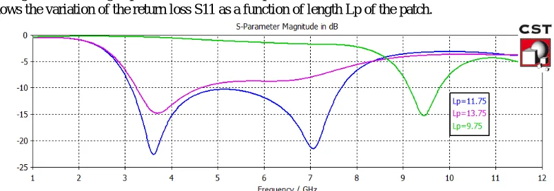
Fig. 8.shows the variation of the return loss S11 as a function of length Lp of the patch.
By increasing and decreasing Lp decrease in B.W. take place but gives narrow bandwidth 9.13-9.79ghz at Lp=9.75mm, & 2.89-3.85ghz at Lg=8mm.
Gain of Proposed Antenna
The fig. 9. presents the proposed antenna gain. The maximum value is obtained at 8GHz. The gain increases steadily from - -11.6db to 4.8 dB between 1GHz and 8GHz, then decreases steadily until 1.4dB between 8 and 10 GHz before returning to growth.
Fig. 9 gain of the proposed antenna
VSWR of Proposed Antenna
Below figure shows the VSWR of proposed Antenna.
Fig 10. VSWR of the proposed antenna.
We get VSWR<2, upto whole bandwidth from 3.13-7.66ghz.
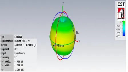
Directivity & Gain of Proposed Antenna at 3.1ghz & 7.6ghz
Fig.11.b. Gain at 3.1GHz
Fig.11.c..directivity at 7.6GHz
Fig.11.d.gain at 7.6GHz
VI.FABRICATED ANTENNA
The negative of the designed antenna fabricated design of the microstrip patch antenna is given in the Figure below. The testing of antenna can be done by using Network Analyzer which analyses one port and two port networks.
Fig.12 Front and back view of Fabricated Antenna
V.CONCLUSION
This Proposed antenna is used for many Wireless applications like W-LAN/IEEE802.11.a (5.15- 5.35GHz, 5.725-5.825GHz), WiMAX (3.3-3.7GHz, 5.25- 5.85GHz), HiperLAN2 (5.47-5.725 GHz) and HiSWaNa (5.15-5.25 GHz) ,Wi-fi (5.2/5.5/5.8ghz), Telecommunications(6.6-7.5ghz), Satellite and Radar Communication(6-7.5ghz),ISM(5-6ghz), wireless application bands, With low cost and ease of design and fabrication.
REFERENCES
[ 1 ] Y. Lu, Y. Huang, Y.C.Shen, and H.T.Chattha, A further study of planar UWB monopole antennas, in Proc. Loughbrough Antennas Propag. Conf. 2007, Sep. 2009, pp. 353-356.
[ 2 ] K. C. L. Chan, Y. Huang, and X. Zhu, A planar elliptical monopole antenna for UWB applications, i n Proc. IEEE/ACES Int. Conf. Wireless Commun. Appl. Comput. Electromagn., Apr. 2005, pp. 182
[ 3 ] Z. N. Chen, M. J. Ammann, X. Qing, X. H. Wu, T. S. P. See, and A. Cat, P l a n a r a n t e nnas,IEEE Microw. Mag., vol. 7, no. 6, pp. 6373, Dec. 2006.
[ 4 ] J. X. Liang, C. C. Chian, X. D. Chen, and C. G. Parini, Study of a printed circular disc monopole antenn a for UWB systems, IEEE Trans. Antennas Propag., vol.53, no. 11, pp. 3500-3504, Nov. 2005.
[ 5 ] M. J. Ammann and M. John, Optimum design of the printed strip monopole, IEEE AntennasPropag.Mag.,vol.47, no. 6, pp. 59-61, Dec. 2005. [ 6 ] Q. B. Ye, Z. N. Chen, and T. S. P. See, Ground plane effect on the performance of a butterfly-shaped UWB monopole, i n Proc. iWAT, Mar. 2008, pp. 334-337.
[ 7 ] S. Curto, M. John, and M. J. Ammann, Ground plane dependent performance of printed antenna for MB-OFDM-UWB, i n Proc. 65th IEEE VTC Spring, Apr. 2007, pp. 352-356.
[ 8 ] Z. N. Chen, T. S. P. See, and X. M. Qing, Small printed ultrawideband antenna with reduced ground plane effect, IEEE Trans. Antennas Propag., vol. 55, no. 2, pp. 383-388, Feb. 2007. Y. Lu, Y. Huang, Y. C. Shen, and H. T. Chattha.
[9] Kumar, G.and K. P. Ray, “Broadband Microstrip Antennas”, Attach House, Boston, 2003.
[10] Y.Yao, B.Huang and Z. Feng, “A novel ultra-wideband Microstrip-line fed wide slot antenna having frequency band-notch functions, International Conference on Microwave and Millimeter Wave Technology (ICMMT), pp.1-4, 18-21 April, Bulin, 2007.
[11] J. Young, J. Cho, K. -H Kim, D. -H Choi, S. -S Lee, and S. -O Park, “ A Miniature UWB Planar Planer Antenna With 5-GHz Band-Rejection Filter and the Time-Domain Characteristics,‟‟ IEEE Trans. Antennas Propag.,. Vol.54, no.5, pp. 1453-1460, May. 2006.
NO.2 MARCH 2010 56 IJMOT-2008-6-323 © 2010 ISRAMT Application,” IEEE Trans. Antennas Propagat., vol.52, N.2. pp. 610-615, February. 2004.
[14] J. L. Pan, S. S. Rappaport, and P. M. Djuric, “A multibeam medium access scheme for multiple services in wireless cellular communications,” in Proc. IEEE 1999 Int. Conf. Communication, vol. 3, 1999, pp. 1673–1677.
[15] L. Jofre, B. A. Cetiner, and F. Flaviis, “Miniature Multi-Element Antenna for Wireless Communications,” IEEE Trans. Antennas Propagat., vol.50, N. 5. pp. 658–669, May 2002.