Numerical Simulation and Experiment Performance for Comparison
of Shell and Tube Heat Exchanger with Plain Tube and Corrugated
Tube
Darshan Patel1, Prexa Parikh2
1
PG Student in Mechanical Engineering Department, L.J.Institute of Engineering & Technology, Ahmedabad-382210, Gujarat, India
2
Assistant Professor in Mechanical Engineering Department, L.J.Institute of Engineering & Technology, Ahmedabad-382210, Gujarat, India
Abstract
Shell and Tube Heat Exchanger in which It is Fixed Tube-sheet and Counter Flow Type Heat Exchanger. Here, Shell side fluid is cold water and tube side fluid is hot water .Cold water is cold fluid And hot water is hot fluid. I do Thermal Designing and Analysis of STHX due to the problem of Large Pressure Drop at shell side, Large Pressure Drop at tube side, Less Heat Transfer rate and Cost is very high and also will do analysis of corrugated tube and compare with existing plain tube. I will make prototype experiment model of shell and tube heat exchanger in which plain and corrugated tube is use one after one and take reading for thermal analysis calculation and then compare Experiment Result to CFD Analysis result for validation. In Computational Fluid Dynamics (CFD) Analysis Software use Solid Works 2014 for Geometry & Modeling ,ICEM CFD (ANSYS 14.5) for Meshing and Fluent for Analysis.
Keywords: heat transfer rate , CFD, shell and tube heat exchanger, flow arrangement.
1. Introduction
A shell and tube heat exchanger is a class of heat exchanger designs. It is the most common type of heat exchanger in oil refineries and other large chemical processes, and is suited for higher-pressure applications. As its name implies, this type of heat exchanger consists of a shell (a large pressure vessel) with a bundle of tubes inside it. One fluid runs through the tubes, and another fluid flows over the tubes (through the shell) to transfer heat between the two fluids. The set of tubes is called a tube bundle, and may be composed of several types of tubes: plain, longitudinally finned, etc. Shell and tube heat exchanger design is based on correlations between the Kern method and Bell-Delaware method[16], Moreover they are versatile and can be designed to suit for almost any application. Shell-and-tube exchangers are designed and fabricated according to the standards of the Tubular Exchanger Manufacturers Association (TEMA).[18] it is used for As process heat exchangers in the petroleum-refining and chemical industries, As steam generator, condensers, boiler feed water heater, and oil coolers in power plant.
Figure 1: Fixed Tube sheet Heat Exchanger[15]
A fixed-tube sheet heat exchanger (Figure 1) has straight tubes that are secured at both ends to tube sheets welded to the shell. The construction may have removable channel covers (e.g., AEL), bonnet-type channel covers (e.g., BEM), or integral tube sheets (e.g.,
NEN). [15]
Components of STHX [15] :
It is essential for the designer to have a good working knowledge of the mechanical features of STHEs and how they influence thermal design. The principal components of an STHE are:
• shell; • shell cover; • tubes; • channel; • channel cover; • tube sheet
Application :
•As action heat exchangers in the petroleum-refining and chemical industries.
•As steam generator, condensers, boiler feed water heater, and oil coolers in power plant.
•In some air-conditioning and refrigeration as condenser and evaporators.
•In waste heat recovery applications with heat recovery from liquids and more dense fluids.
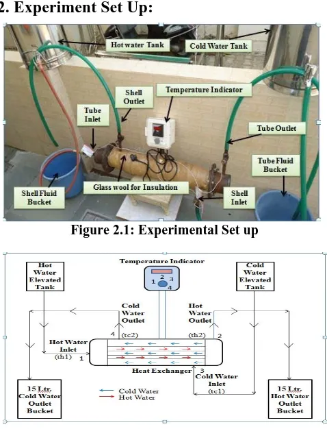
2. Experiment Set Up:
Figure 2.1: Experimental Set up
Figure 2.2 : Schematic Diagram of Experiment Layout
In this experimental work ,hot water is flow at tube side and cold water is flow at shell side. here 15 litr outlet bucket is used for supplied both fluid at respective side. Experiment is started and temperature reading is taken at every 5 minute interval. temperature reading is done by putting temperature indicator with sensor. It measure temperature of both fluid th1,th2,tc1,tc2. hot fluid and cold flow in opposite Direction so counter flow can be achieve for obtaining high heat transfer rate. hot water flow indicated by blue color and cold water indicated by red color.
Experiment Result:
Hot Fluid Hot water
Hot water Mass Flow Rate 0.05kg/s
Hot water Inlet Temperature 328.25 K
Hot Water Outlet Temperature 320.68 K
Cold Fluid Cold Water
Cold Water Mass Flow Rate 0.04666 kg/s
Cold Water Inlet Temperature 310.48 K
Cold Water Outlet Temperature 316.24 K
3. Modeling and Meshing of Shell and Tube
Heat
Exchanger:
(in Solid Works14)
Figure 3.1: Assembly of Shell & Tube Heat Exchanger
Meshing:
By using Ansys 14.5, meshing of STHX is done.
Figure 3.2: Meshing of STHX with Plain Tube
3.1 CFD Analysis :
By using Fluent 14.5 ,CFD of STHX is done.
Figure 3.4: Pressure Variation in STHX with Plain Tube
Result:
Parts Operating
Parameter Parameter Value
Tube Inlet
Temperature
328.25 K
Static Pressure
57.49 Pa
Velocity
0.1311 m/s
Area
0.00031195983
m
2Tube Outlet
Temperature
323.0408 K
Static Pressure
13.14 Pa
Velocity
0.1395 m/s
Area
0.00031193078
m
2Shell Inlet
Temperature
310.48001 K
Static Pressure
34.49 Pa
Velocity
0.1230 m/s
Area
0.00031184437
m
2Shell Outlet
Temperature
316.03424 K
Static Pressure
11.89 Pa
Velocity
0.1322 m/s
Area
0.00031189778
m
2Comparison of Results:
Parameter Experimental Result
CFD
Result
%
(Diff)
Hot Water
Inlet Temp.
328.25 K
328.25
K
0 %
Hot Water
OutletTemp
.
321.41 K
323.04K
0.0050
714%
Cold Water
Inlet Temp.
310.48 K
310.48K
0%
Cold Water
OutletTemp
.
315.96 K
316.03
K
0.0002
348%
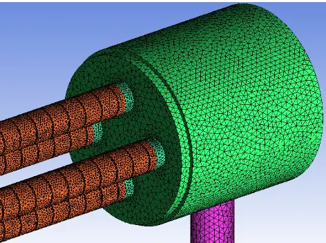
4. Modeling and Meshing of STHX with
Corrugated Tube:
Figure 4.1: 3D Model of Corrugated Tube Section Configuration
Meshing:
Figure 4.3:Enlarge View of Meshing on STHX Model with Corrugated Tube
4.1 CFD Analysis : (STHX with Corrugated Tube)
By using Fluent 14.5 ,CFD of STHX is done. Same boundary conditions are applied as previous case.
Results:
Figure4.4:Temperature Variation in STHX with Corrugated Tube
Figure4.5: Pressure Variation in STHX with Corrugated Tube
Figure4.6: Velocity Variation in STHX with Corrugated Tube
Results: (for corrugated tube from CFD Analysis)
Parts Operating parameter
Parameter value
Tube Inlet
Static Temperature 328.25 K
Static Pressure 109.82466 Pa
Velocity 0.16028699 m/s
Area 0.00031250296 m2
Tube Outlet
Static Temperature 321.70 K
Static Pressure 10.783895 Pa
Velocity 0.16021301 m/s
Area 0.00031282400 m2
Shell Inlet
Static Temperature 310.48001 K
Static Pressure 41.702805 Pa
Velocity 0.14951903 m/s
Area 0.00031263 m2
Shell Outlet
Static Temperature 315.38669 K
Static Pressure 9.9446163 Pa
Velocity 0.14945887m/s
Comparison of two tubes:
Parameter CFD Result For corrugat ed tube CFD Result For plain tube Difference Remark
Hot Water Inlet Temp. 328.25 K 328.25
K 0 -
Hot
Outlet
Temp.
323. K 323.040
K 0.04
Cooling of Hot Water increase Cold Water Inlet Temp. 310.48 K 310.48
K 0 -
Cold Water Outlet Temp. 315.386 69 K 316.034
K 0.648
Heating of Cold Water increase Pre. drop on tube side 60.048 Pa 28.04
Pa 32 Pa
Pressure drop on corru.tube side increase Pressure drop on shell side 31.76
Pa 22.6 Pa
9.16 Pa Pressure drop on plain tube side decrease
5.Conclusion:
CFD analysis result shows that increasing in temperature difference by using corrugated tube.
CFD analysis result shows that pressure drop on plain tube side also reduce.
Heat transfer rate increase due to increase in temp. diff.
there is grooving cutting can be done on plain tube so to obtain corrugated shape. but there is pressure drop is created more than plain tube but it is in suitable limit. so we can consider our design of heat exchanger is safe. efficiency and effectiveness is increase for corrugated
tube compare to plain tube from CFD result.
from above result we say that our design is safe to help to increase performance of heat exchanger.
References
[1] Byung-Hyun Jang, Byeong-Ha Jeon, Kwon-Hee Lee, Dong-a University (BUSAN 604-714Korea) ,"A Numerical Analysis for the Performance Improvement of Channel Heat Exchanger" , Models and Methods in Applied Sciences, ISBN : 978-1-61804-082-4 (2011), pp.158-162.
[2] Folaranmi Joshua, Federal University of Technology, Minna, Niger State, Nigeria, "Design and Construction of a Concentric Tube Heat Exchanger”, AU.J.T. 13-2: (Oct. 2009), pp.128-133.
[3] Chandrakant B. Kothare, Department of Mechanical Engg. Shri. Shankarprasad Agnihotri College of Engg. Wardha, Maharashtra., India. "Shell and Tube Heat Exchanger design by VB Language for Education Purpose”, International Journal of Modern Engineering Research (IJMER), Vol.1, Issue2, ISSN:2249-6645(2010), pp.652-657.
[4] C. Z. Patel, Prof. K. K. Araniya, Prof. V. Y. Gajjar, Prof. H. B. Nayak, Prof. B.B. Patel ,“CFX validation of shell and tube Heat Exchanger at Thermal Power Station”, International Journal of Engineering Technology and Advanced Engineering ISO 9001: 2008 Certified Journal ISSN:2250-2459, Volume 4, ISSUE 4, (April 2014), pp.167-171.
[5] C.Sivarajan, B.Rajasekaran, Dr.N.Krishnamohan, Department of Mechanical Engineering Annamalai University Annamalai Nagar 608002 India" Comparison of Numerical Heat Transfer in Conventional and Helically Baffled Heat Exchanger" ,International Journal of Engineering Research and Applications (IJERA) Vol. 2, Issue 2, ISSN: 2248-9622 (Mar-Apr 2012), pp.1278-1282.
[6] Farhad Nemati Taher, Sirous Zeyninejad Movassag, Kazem Razmi, Reza Tasouji Azar, Department of Mechanical Engineering, Ilkhchi Branch, Islamic Azad University, ilkhchi, Iran “Baffle Space Impact on the Performance of Helical Baffle Shell and Tube Heat Exchanger” , Applied Thermal Engineering 44 (27 March- 2012) , pp.143-149.
and Mechanical Engineering 14(2014), (15 Aug 2013), pp. 489-496.
[8] Kevin M. Lunsford, Bryan Research & Engineering, Inc., Bryan Texas ," Increasing Heat Exchanger Performance" Bryan Research And Engineering, Inc. - Technical Papers , (March 1998), pp.1-13.
[9] Liljana Markovska, Vera Mesko~Radmila Kiprijanova, Aleksandra Grizo, "Optimization of Shell and Tube Heat Exchanger By Optimization Software Packages", Bulletin of the Chemists And Technologists of Macedonia, Vol.15, No.1, ISSN:350-0136 (1996), pp.39-44.
[10] Pawan P. Singh, University of Idaho, Moscow, Idaho, U.S.A., "Thermal Design of Heat Exchangers", Marcel Dekker, Inc, 270 Madison Avenue, New York, New York-10016. DOI: 10.1081/E-EAFE 120007010 (2004). [11] Su That Mon Than, Khin Aung Lin, Mi Sandar Mon,
"Heat Exchanger Design", World Academy of Science, Engineering And Technology 46 (2008), pp.604-611. [12] Ventsislav Zimparov Plamen Penchev Department of
Mechanical Engineering, Gabrovo Technical University, 4, H.Dimitar, Str.,5300 Gabrovo, Bulgaria, "Performance Evaluation of Deep Spirally Corrugated Tube Type Shell And Tube Heat Exchanger", Id041501,3rd International Symposium on Heat Transfer Enhancement And Energy Conservation, Guangzhou, China (1998), pp.1-10
[13] Shiv Kumar Rathore, Ajeet Bergaley, "Comparative Analysis of Finned Tube and Bared Tube Shell And Tube Heat Exchanger" ISSN: 2277-3754 ISO 9001:2008 Certified, Issue 1 International Journal of Engineering And Innovative Technology (IJEIT) Volume 2(July 2012), pp.64-72.
[14] Kirtan Gohel, “Effectiveness Improvement of Shell And Tube Heat Exchanger”, International Journal of Innovative Research in Science, Engineering and Technology (IJIRSET) Vol 3, Issue 11, ISSN: 2319-8753 (An ISO 3297:2007 Certified Organization) (Nov 2014), pp.17200-17204.
[15] Tabular Exchanger Manufacturers Association (TEMA Standards - 9th Edition), pp.5.3-1, 7-1 (2007).
[16] Mukherjee Rajiv, Chemical Engineering Process, Engineers India Ltd, (Feb 1998), pp.1-17.
[17] Viska Mulyandasari, Practical Engineering Guideline For Processing Plant Solution By KLM Technology Group [Section: Heat Exchanger Selection & Sizing (Engineering Design Guideline)] (Nov 2010), pp. 1-23. [18] Rajput R. K., Heat And Mass Transfer, S. Chand
Publication, pp.574 (1999).
[19] Kakac Sadik, Heat Exchangers-Selection, Rating And Thermal Design, ;2nd Edn.; CRCPress, Washington,1997, pp 250-295.
![Figure 1: Fixed Tube sheet Heat Exchanger[15] A fixed-tube sheet heat exchanger (Figure 1) has straight tubes that are secured at both ends to tube sheets welded to the shell](https://thumb-us.123doks.com/thumbv2/123dok_us/7833604.1298089/1.612.320.533.230.358/figure-fixed-exchanger-exchanger-figure-straight-secured-sheets.webp)